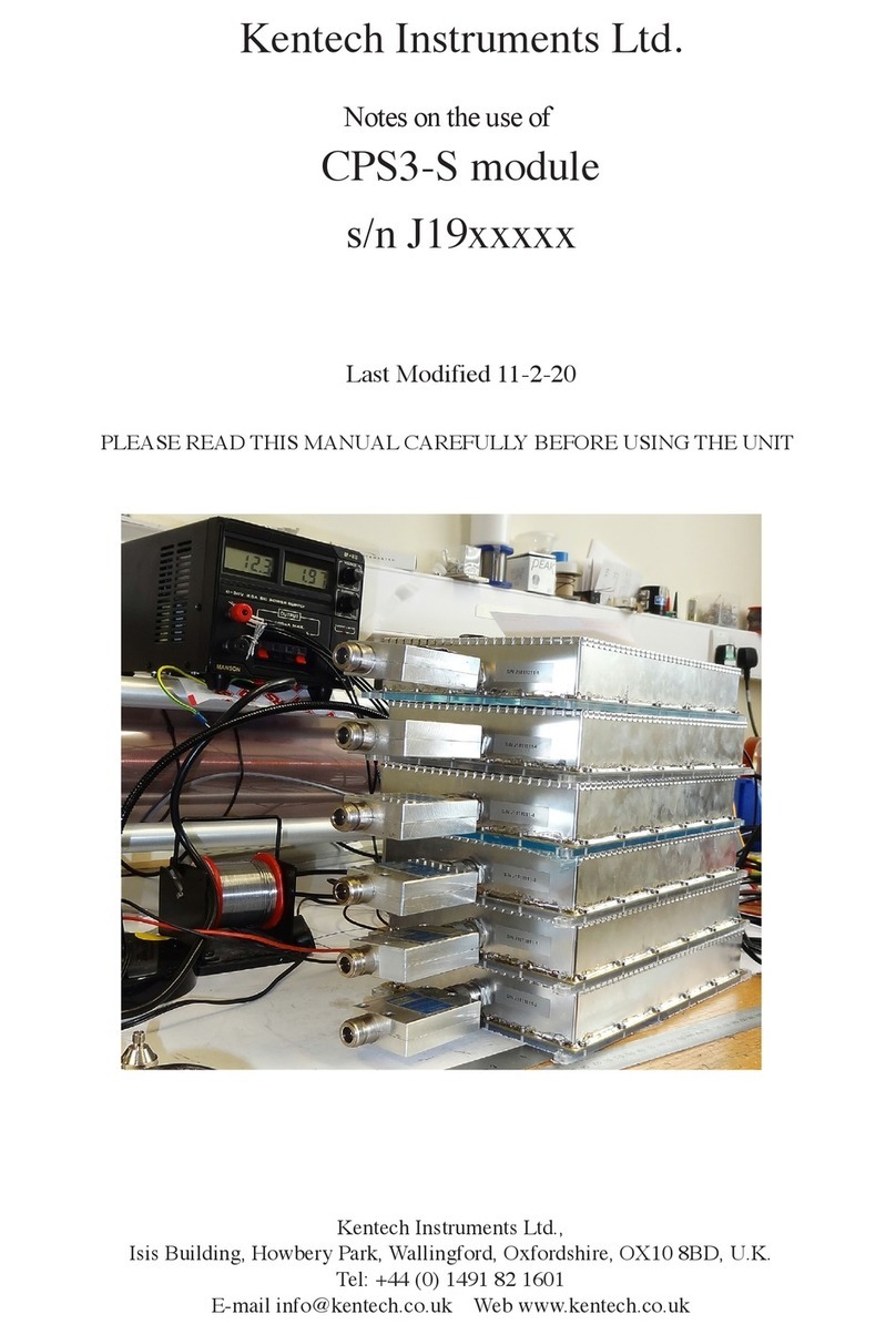
Kentech Instruments PBG7 User manual

Kentech Instruments Ltd.
Notes on the use of
PBG7 pulser system
Serial No. (special)
It is important to read this manual before operating the
system.
2nd April 2004

Caution
PBG7 Pulser System Serial No. xxxxx
This equipment is a scientific research tool that has been intentionally designed to generate
short high energy ultrawideband electromagnetic pulses and the EM emissions will be highly
sensitive to the load applied by the user. It is suitable for use only in a sealed electromagnetic
or laboratory environment, unless it is used in a system that has been verified by the system
builder to comply with EC directive 89/336/EEC. It will interfere with and may damage
sensitive equipment in the local environment. Use of this equipment outside of a sealed
electromagnetic or laboratory environment may result in prosecution. This equipment must
not be used or operated in a domestic environment or as part of a safety critical or life support
system.
With an appropriate load, and when fitted into a suitable 19” rack system that prevents
access to the rear panel connectors, the unit is safe for use by personnel with relevant
technical qualifications and UWB training in a laboratory environment . You are warned
however that the radiation from the system with an antenna or inappropriate load attached
can damage sensitive equipment and corrupt data stored in computer and microprocessor
based systems including aeronautical and other safety critical systems. It can cause terminal
failure of vital medical electronic systems such as pacemakers and other life support systems
and it can inhibit and damage communications systems. The main 45kV 150ps output is likely
to be particularly damaging but the 12kV 100ps and 6kV 100ps outputs must also be treated
with caution.
This equipment is supplied on the understanding that the user will analyse these risks, accept
responsibility for them and take appropriate precautions in the use of this instrument.
The pulse outputs from this pulse generator will destroy most types of power attenuators and
electronic test equipment. It is the users responsibility to ensure that any apparatus connected
to the output is suitably rated.
Kentech Instruments Ltd accepts no responsibility for any damage or liabilities incurred in the
operation of this equipment.
The system contains 120W of 4kV power supplies, this can cause death or injury from burns

and electric shock. Do not remove covers. Return to Kentech Instruments Ltd. for servicing.
Clean only with soft dry cloth.
Check that all relevant connectors are in place on the rear panels before applying ac power.
Do not disconnect the multiway connectors on the rear of the PBG7 45kV output module
and PBG7 HV power supply module for 3 minutes after removing ac power.
The equipment must be grounded via the power connector to maintain protection from
electric shock.

Introduction
This PBG7 system is a state of the art avalanche pulser utilising a series parallel
array of avalanche stacks coupled with various transformers to generate a large single output
amplitude of *45kV into 501.
The instrument consists of five 19” rack mounting modules which should be
mounted into a single 19” enclosure that prevents access to the rear panel connectors. These
are:-
1. PBG7 control and trigger module
2. Four channel delay module
3. PBG5 four channel trigger module
4. PBG7 45kV output module
5. PBG7 HV power supply module
The system can be operated in each of three configurations:-
PBG1 configuration. One output signal is taken from the 6kV output on the PBG7 control
and trigger module, the other four modules are disconnected and not used.
PBG5 configuration. Four output signals are taken from the four 12kV outputs on the PBG5
four channel trigger module. The PBG7 control and trigger module, Four channel delay module
and PBG5 four channel trigger module are used, the other two modules are unused and
disconnected.
PBG7 configuration. One output signal is taken from the 45kV output on the PBG7 45kV
output module. All modules are used except the four channel delay module which should
always remain powered down but must remain in circuit to preserve correct trigger timing.
Note that for each configuration it is necessary to configure both hardware and software - see
below.

The PBG7 control and trigger module is 3U high and contains the microprocessor and low
voltage trigger electronics and a PBG1 type pulse output board generating approx 6kV
amplitude into 501with a risetime <150ps. In PBG5 or PBG7 configurations the output must
be connected using the short N to N type 501conformable cable provided to the internal 4
way splitter. This generates 4 approximately simultaneous trigger signals to be used to trigger
the PBG5 four channel trigger module. The rear panel has a female 9 way D type connector for
RS232 to an optional computer and a male 9 way D connector which is for system control. In
PBG5 or PBG7 configurations the sysytem control should be connected to the PBG5 four
channel trigger module using the screened D to D type lead provided. There are also one IEC
power inlet and two IEC power outlets which should be used to power the PBG5 four channel
trigger module and PBG7 HV power supply module.
The four channel delay module is 3U high and sits between the PBG7 control and trigger
module and the PBG5 four channel trigger module. Except in PBG1 configuration it should be
connected to both these modules using the 8 BNC to BNC cables provided. It’s function is to
allow independent variation of the delay of the 4 trigger signals in PBG5 configuration to allow
beam steering using a 4 element antenna array. In PBG7 configuration the delay module is not
used and should remain connected via the 8 BNC to BNC cables but powered down. This
module is completely independent of the rest of the system, it has it’s own microprocessor with
RS232 connection and power input on the rear panel and no connection to the system control
link.
PBG5 four channel trigger module is 6U high. It has four BNC trigger inputs and four high
voltage HN pulse outputs of approx 12kV amplitude into 501. In PBG7 configuration these
outputs are used to trigger the PBG7 45kV output module using the 4 HN to HN cables
provided. In PBG5 configuration the outputs can be used to drive an antenna array. The IEC
power input must be connected to an outlet on the PBG7 control and trigger module. The 9
way D type control link connectors are daisy chained together, one must be connected to the
PBG7 control and trigger module and one to the PBG7 HV power supply module.
PBG7 45kV output module is 9U high. It has four HN 12kV trigger inputs and one pulse
output of approx 45kV amplitude using a special Kentech connector. On the rear panel are six
multiway connectors and two D type connectors which must be connected to the PBG7 HV
power supply module using the cables provided.
PBG7 HV power supply module is 3U high. The six multiway and two D type connectors on

the rear panel must be connected to the PBG7 45kV output module. The IEC power input
must be connected to an outlet on the PBG7 control and trigger module.
Use
The equipment should be mounted in a suitable 19” rack. The rear panel and front panel
connections should be added depending on the configuration required (PBG1, PBG5 or PBG7)
as shown in the diagram below.
Note that ac power for the PBG5 four channel trigger module and PBG7 HV power supply
module must be taken from the PBG7 control and trigger module using the IEC male/female
leads supplied. The front panel switch will therefore switch power to all three modules. This is
important for the software to power up correctly. The four channel delay module is completely
independent and should have its independent power supply. The external ac power required is
110 to 240V 50 or 60Hz, approx 250W.
The system is air cooled and at maximum repetition rate the air cooled system will dissipate
approximately 250W of thermal power, consequently it requires an adequate and unobstructed
flow of clean air.
RF emission from the circuitry inside the PBG5 four channel trigger module and particularly
the PBG7 45kV output module is severe, the modules rely upon the integrity of their enclosures
to contain the radiation. Further, because of the high power and high frequency requirements
the the modules use their chassis as ground return and screen. Therefore it is important for
correct operation that all covers remain in place, all screws and fasteners remain secure, and the
equipment is earthed via the power lead.
The PBG5 four channel trigger module, PBG7 45kV output module and PBG7 HV power
supply module are controlled and tested by the microprocessor in the trigger unit by means of
the various control and monitor links on rear panels. It is important that all rear panel
connections are configured correctly and all connectors with locking screws are tightened
correctly.

If remote control by RS232 is employed we recommend that only screened cables should be
use and that the cables should be fitted with clamp on ferrites near to the PBG7 system.
The trigger signal can be generated internally or applied externally to the trigger unit. When
external triggering is used, the trigger signal should be *5 volts into 501with a fast rising edge
(<5ns) to maintain the low jitter of the system. Do not trigger the generator at a rate in excess
of 500Hz. The external trigger input is a BNC connector mounted on the front panel. When the
trigger unit is triggered the “triggered” LED on the front panel will flash.
There are an additional “triggered” LEDs on the PBG5 four channel trigger module and PBG7
HV power supply module showing the state of the trigger stacks.
In the internal trigger, single shot and delayed modes there is an internal delay which may be
adjusted by the user. Another front panel BNC connector “pre-trigger output” provides a
signal of ~10V into 501. This is approximately synchronous with the trigger, in advance of the
high voltage pulse output and may be used to trigger auxiliary equipment such as a sampling
oscilloscope. There are thermal drifts in the delay generator which will stabilise after the pulser
has been switched on for ~20 minutes.
The internal trigger generator will only run if the inhibit BNC is shorted, if remote control is not
required this may be conveniently achieved using the 501terminator supplied, plugged onto
the connector.
In “direct” mode the external trigger signal is applied directly to the avalanche stack and the
low level circuitry is bypassed to give the minimum trigger delay. There is no monitor output
generated in this mode.
The main output of the PBG7 45kV output module appears at the front panel connector which
is a special connector of Kentech design. There are drawings of this connector at the rear of this
manual to allow the user to manufacture additional units as required. The pulser will tolerate
open circuit, short circuit and arc loads at the end of a 501cable longer than 1m. However
prolonged operation like this without a resistive load to dissipate residual energy from the pulse
may degrade the lifetime of the insulator in the output connector. This is because the pulse
energy is trapped within the output cable for a prolonged time and may cause partial discharges
which erode the insulation. We believe the worst case scenario from this perspective is a short
circuit at the end of a few nanoseconds of cable.

It is not necessary to have a well matched 501 load to preserve pulser lifetime, but we
recommend the load should present a dc resistive load to the pulser in the range of approx 25
to 100 ohms.
If it is necessary to monitor or characterise the pulse output then suitable attenuators must be
used. The 12kV and 45kV pulse outputs from this unit are capable of destroying most
types of power attenuators and terminators including most of the high pulse power
types.The pulser was characterised at the factory using two methods:-
a) For the 12kV outputs a x2 Kentech suicide T attenuator was followed by two x10 Barth
142-NMFP-20 attenuators then two radial x10 attenuators. These outputs unit will destroy the
Barth 142 if used without the T.
b) For the 45kV output a special x10 Kentech resistive attenuator was used followed by two
x10 Barth 142-NMFP-20 attenuators then two radial x10 attenuators.
See the photographs enclosed in this manual.
The output may be observed with a high bandwidth oscilloscope. This may either be a fast
(>3GHz) single shot type or a sampling type.
If the output of the pulser is to be used directly or via any passive network it is essential that
cable lengths are kept as short as possible and that only high quality cable is used. This will
enable the fast rising edge generated by the unit to reach the load without serious degradation.
The PBG7 is controlled by the microprocessor unit with LCD display and four button keypad.
On power up, the trigger input of the avalanche stack is disabled, note that it is always
necessary to issue commands to the microprocessor unit via the keyboard or the RS232
interface to enable the trigger circuit and make the pulser run normally. Please see the software
section below.
The µP unit includes a self test routine. This should be run at least once a day at power up, or at
any change of configuration and any faults noted, see sections on stack faults and comms faults
below. Otherwise there is no regular maintenance required. There is some redundancy in the
unit by virtue of its design, and the unit may continue to operate at slightly reduced amplitude

with several faults present. The switching elements in these avalanche pulsers generally have a
long life, but their life is finite and therefore it is sensible to switch off the unit or at least not
trigger it when it is not required. It is not possible to write a test routine to find 100% of all
possible faults, so if the unit appears to malfunction, and the procedures below fail to isolate the
problem please contact Kentech Instruments for advice.
There is a facility provided under the Stack Status menu to disable individual stacks. This may
be used in certain circumstances to disable faulty stacks that are causing problems. It is also
permissible to use this facility to disable output stacks to reduce the output amplitude. Note this
information is stored in non volatile memory, ie it will be remembered even when ac power is
removed. If the output amplitude appears low please check under the system status menu that
all 86 stacks are enabled.
IMPORTANT
When fitting the output connector ensure that:
i) all six fixing screws are tightened to maintain a low impedance ground connection
ii) the plastic insulating collar and sprung centre contact are fitted
Failure to fit the fixing screws will result in severe RF emission.

PBG7 V1.0 Software
The microprocessor used is a Hitachi H8/532 running a FORTH operating system and it is
programmed in the FORTH programming language. It is not necessary to have any knowledge
of the H8 or FORTH to operate the pulser.
a) Main menu
On power up or on entering LOCAL mode from remote, the unit will briefly display the
“Kentech Instruments” banner and then the main menu:-
Run... >
Test menu... >
System status... >
Stack status... >
The cursor will be under Run as shown, press the up and down keys to select one of Run,
Test , System status or Stack status then press the right key to execute. While the main menu is
displayed, the serial port is monitored. If the µP receives a character it will enter REMOTE
mode.
b) Run
The display will indicate that the pulser is running and the configuration selected ( see system
status to edit configuration).
<Running
PBG7 Configuration
The HT is switched on to each enabled stack. The trigger is enabled, and the unit will now run
normally while waiting for the user to press a key. All keys are ignored except for left which
causes the trigger to be disabled, the HT to be switched off and a return to the main menu

c) Test menu
<Voltage test... >
Test mode 7... >
Test mode 5... >
Press up or down for appropriate selection, then right to select.
d) Voltage test
The display will indicate that the pulser is being tested and the configuration selected ( see
system status to edit configuration).
Testing...
PBG7 Configuration
First, depending on the configuration the processor checks that it can communicate with the
PBG5 four channel trigger module and the PBG7 HV power supply module.
Then each of a total of up to 86 stacks is powered up in turn. Its voltage is measured and
checked to be within acceptable limits. This takes a few seconds, during this period all keys are
ignored.
Finally a summary of the test is displayed
<PBG7 system tested
PBG5 comms pass
PBG7 comms fail
3 stacks faulty
The first line displays the configuration selected. The second and third lines display the status of
the necessary system control links for this confguration to each of the PBG5 four channel
trigger module (PBG5) and PBG7 HV power supply module (PBG7). If a comms fail is
indicated it is necessary to investigate and rectify. Note that modules that are not powered up
should be disconnected from the control link.

The fourth line displays the number of stacks whose voltage is outside the test limits. Only faults
in stacks that are enabled are counted. Press left to return to main menu.
d) Test mode 7
<PBG7Row# {S22} = 0
Run -row... >
PBG7Card# = 0
Run -card... >
Test mode 7 is provided to help to isolate faulty stacks within the PBG7 module using a matrix
method.
The first and third line allow the selection of a row number and card number respectively within
the PBG7 module. The second and third line allow one to run the pulser with a complete row
of stacks disabled or a complete card disabled respectively. For any given row number and card
number there is just one stack in common, this number is displayed in brackets after “S” on
line one.
See Dealing with stack faults for details of useage.
e) Test mode 5
<PBG5Row# {S 2} = 0
Run -row... >
PBG5Card# = 0
Run -card... >
Test mode 5 is provided to help to isolate faulty stacks within the PBG5 module using a matrix
method.
The first and third line allow the selection of a row number and card number respectively within
the PBG5 module. The second and third line allow one to run the pulser with a complete row
of stacks disabled or a complete card disabled respectively. For any given row number and card
number there is just one stack in common, this number is displayed in brackets after “S” on
line one.

See Dealing with stack faults for details of useage.
f) System status
The display will indicate the system status page.
<Config = PBG7
82 stacks enabled
Test results... >
The cursor will be under Config as shown.
From this cursor postion:-
Left returns to main menu
Right moves cursor to under PBG7, press up/down to edit configuration then left to exit.
Down moves cursor to under Test, right displays the test result summary as above.
The configuration is kept in nonvolatile memory, it is stored as you exit the system status page.
Therefore if you have edited the configuration you will see this message momentarily as you
exit.
Saving user data..."
g) Stack status
The selected stack number is displayed.
<Stack#= 20
( PBG5 stack# 18 )
Enable= 1
Test% = 100 99 99

The cursor will be under Stack as shown.
From this cursor postion:-
Left returns to main menu
Right moves cursor to under 20, press up/down to change selected stack then left to exit.
Down moves cursor to under Enable
With cursor under Enable
Right moves cursor under 1
The configuration is kept in nonvolatile memory, it is stored as you exit the system status page.
Therefore if you have edited the configuration you will see this message momentarily as you
exit.
The state of the ENABLE flag is displayed. Press Down/No to return to the FAULT flag
display, Left or Right to toggle the flag, Up/Yes has no effect. The ENABLE flags are stored in
battery backed RAM.
h) REMOTE
The µP will enter REMOTE mode if it receives an ESC character while displaying the main
menu. In REMOTE, the unit accepts commands in simple ASCII characters and transmits its
responses. There is no handshake, this mode is designed to work with a simple terminal or
terminal emulator.
On entering REMOTE, the µP prints a “Kentech Instruments” banner, then waits for the user
commands. The commands are:-
RUN {cr} to enable all stacks with enable flag set and trigger, thereafter any character will
terminate run mode and disable all stacks
TEST {cr} to run self test routine and print out a summary of results

.TESTRESULTS {cr} to print out summary of test results from the self test routine
PBG1CONFIG {cr} to select PBG1 configuration, you need also to change hardware
PBG5CONFIG {cr} to select PBG5 configuration, you need also to change hardware
PBG7CONFIG {cr} to select PBG7 configuration, you need also to change hardware
.STATUS {cr} to give a listing of status information, ie the current configuration setting and
the number of stacks enabled
n .STACKSTATUS {cr} to give a listing of status information for stack n, ie the location
within the sytem, the state of the enable flag and any test voltages as a % of initial value
.ALLSTATUS {cr} to give a listing of status information and stack information for all stacks
n +ENABLE {cr} to set high the enable flag for stack no. n
n -ENABLE {cr} to reset low the enable flag for stack no. n
LOCAL {cr} to return to local mode ok
On returning to local mode, the “Kentech Instruments” banner is displayed once again on the
LCD, quickly followed by the main menu.
i) Example dialogue in REMOTE mode
Transmitted commands are shown in red
TDS2020 Fig-FORTH Triangle Digital Services Ltd Ver 2.13
ok
RUN
Running PBG7 configuration
Press any key to stop
Stopped ok
TEST
Testing PBG7 configuration
PBG7 system tested
PBG5 comms pass
PBG7 comms pass
0 stacks faulty ok
.TESTRESULTS

PBG7 system tested
PBG5 comms pass
PBG7 comms pass
0 stacks faulty ok
PBG1CONFIG ok
.STATUS
PBG1 configuration
2 stacks enabled ok
PBG7CONFIG ok
.STATUS
PBG7 configuration
86 stacks enabled ok
ok
42 .STACKSTATUS
Stack#= 42 (PBG7 stack# 20) Enable= 1 Test% = 100 100 100 ok
42 DISABLE DISABLE ? - UNDEFINED
ok
42 +ENABLE ok
42 .STACKSTATUS
Stack#= 42 (PBG7 stack# 20) Enable= 1 Test% = 100 100 100 ok
42 -ENBLE -ENBLE ? - UNDEFINED
42 -ENABLE ok
42 .STACKSTATUS
Stack#= 42 (PBG7 stack# 20) Enable= 0 Test% = 100 100 100 ok
.STATUS
PBG7 configuration
85 stacks enabled ok
42 +ENABLE ok
.STATUS
PBG7 configuration
86 stacks enabled ok
.ALLSTATUS
PBG7 configuration
86 stacks enabled
Stack#= 0 (PBG1 stack# 0) Enable= 1 Test% = 100 100 100
Stack#= 1 (PBG1 stack# 1) Enable= 1 Test% = 100 100 100

Stack#= 2 (PBG5 stack# 0) Enable= 1 Test% = 100 100 100
Stack#= 3 (PBG5 stack# 1) Enable= 1 Test% = 100 100 100
Stack#= 4 (PBG5 stack# 2) Enable= 1 Test% = 99 99 100
Stack#= 5 (PBG5 stack# 3) Enable= 1 Test% = 100 99 100
Stack#= 6 (PBG5 stack# 4) Enable= 1 Test% = 100 100 100
Stack#= 7 (PBG5 stack# 5) Enable= 1 Test% = 100 100 100
Stack#= 8 (PBG5 stack# 6) Enable= 1 Test% = 100 100 100
Stack#= 9 (PBG5 stack# 7) Enable= 1 Test% = 99 99 100
Stack#= 10 (PBG5 stack# 8) Enable= 1 Test% = 100 100 100
Stack#= 11 (PBG5 stack# 9) Enable= 1 Test% = 100 100 100
Stack#= 12 (PBG5 stack# 10) Enable= 1 Test% = 100 100 100
Stack#= 13 (PBG5 stack# 11) Enable= 1 Test% = 100 100 100
Stack#= 14 (PBG5 stack# 12) Enable= 1 Test% = 100 99 100
Stack#= 15 (PBG5 stack# 13) Enable= 1 Test% = 100 100 100
Stack#= 16 (PBG5 stack# 14) Enable= 1 Test% = 100 100 100
Stack#= 17 (PBG5 stack# 15) Enable= 1 Test% = 100 100 100
Stack#= 18 (PBG5 stack# 16) Enable= 1 Test% = 100 100 100
Stack#= 19 (PBG5 stack# 17) Enable= 1 Test% = 100 100 100
Stack#= 20 (PBG5 stack# 18) Enable= 1 Test% = 100 99 100
Stack#= 21 (PBG5 stack# 19) Enable= 1 Test% = 100 99 100
Stack#= 22 (PBG7 stack# 0) Enable= 1 Test% = 100 100 100
Stack#= 23 (PBG7 stack# 1) Enable= 1 Test% = 100 100 100
Stack#= 24 (PBG7 stack# 2) Enable= 1 Test% = 100 100 100
Stack#= 25 (PBG7 stack# 3) Enable= 1 Test% = 100 100 100
Stack#= 26 (PBG7 stack# 4) Enable= 1 Test% = 100 100 100
Stack#= 27 (PBG7 stack# 5) Enable= 1 Test% = 100 100 100
Stack#= 28 (PBG7 stack# 6) Enable= 1 Test% = 100 100 100
Stack#= 29 (PBG7 stack# 7) Enable= 1 Test% = 100 100 100
Stack#= 30 (PBG7 stack# 8) Enable= 1 Test% = 100 100 100
Stack#= 31 (PBG7 stack# 9) Enable= 1 Test% = 100 100 100
Stack#= 32 (PBG7 stack# 10) Enable= 1 Test% = 100 100 100
Stack#= 33 (PBG7 stack# 11) Enable= 1 Test% = 100 100 100
Stack#= 34 (PBG7 stack# 12) Enable= 1 Test% = 100 100 100
Stack#= 35 (PBG7 stack# 13) Enable= 1 Test% = 100 100 100
Stack#= 36 (PBG7 stack# 14) Enable= 1 Test% = 100 100 100
Stack#= 37 (PBG7 stack# 15) Enable= 1 Test% = 100 100 100

Stack#= 38 (PBG7 stack# 16) Enable= 1 Test% = 100 100 100
Stack#= 39 (PBG7 stack# 17) Enable= 1 Test% = 100 100 100
Stack#= 40 (PBG7 stack# 18) Enable= 1 Test% = 100 100 100
Stack#= 41 (PBG7 stack# 19) Enable= 1 Test% = 100 99 100
Stack#= 42 (PBG7 stack# 20) Enable= 1 Test% = 100 100 100
Stack#= 43 (PBG7 stack# 21) Enable= 1 Test% = 100 100 100
Stack#= 44 (PBG7 stack# 22) Enable= 1 Test% = 100 100 100
Stack#= 45 (PBG7 stack# 23) Enable= 1 Test% = 100 100 100
Stack#= 46 (PBG7 stack# 24) Enable= 1 Test% = 100 100 100
Stack#= 47 (PBG7 stack# 25) Enable= 1 Test% = 100 100 100
Stack#= 48 (PBG7 stack# 26) Enable= 1 Test% = 100 100 100
Stack#= 49 (PBG7 stack# 27) Enable= 1 Test% = 100 100 100
Stack#= 50 (PBG7 stack# 28) Enable= 1 Test% = 100 100 100
Stack#= 51 (PBG7 stack# 29) Enable= 1 Test% = 100 100 100
Stack#= 52 (PBG7 stack# 30) Enable= 1 Test% = 100 100 100
Stack#= 53 (PBG7 stack# 31) Enable= 1 Test% = 100 100 99
Stack#= 54 (PBG7 stack# 32) Enable= 1 Test% = 100 100 100
Stack#= 55 (PBG7 stack# 33) Enable= 1 Test% = 100 100 100
Stack#= 56 (PBG7 stack# 34) Enable= 1 Test% = 100 100 100
Stack#= 57 (PBG7 stack# 35) Enable= 1 Test% = 100 100 99
Stack#= 58 (PBG7 stack# 36) Enable= 1 Test% = 100 100 100
Stack#= 59 (PBG7 stack# 37) Enable= 1 Test% = 100 100 100
Stack#= 60 (PBG7 stack# 38) Enable= 1 Test% = 100 100 100
Stack#= 61 (PBG7 stack# 39) Enable= 1 Test% = 100 99 100
Stack#= 62 (PBG7 stack# 40) Enable= 1 Test% = 100 100 100
Stack#= 63 (PBG7 stack# 41) Enable= 1 Test% = 100 100 100
Stack#= 64 (PBG7 stack# 42) Enable= 1 Test% = 100 100 100
Stack#= 65 (PBG7 stack# 43) Enable= 1 Test% = 100 100 100
Stack#= 66 (PBG7 stack# 44) Enable= 1 Test% = 100 100 100
Stack#= 67 (PBG7 stack# 45) Enable= 1 Test% = 100 100 100
Stack#= 68 (PBG7 stack# 46) Enable= 1 Test% = 100 100 100
Stack#= 69 (PBG7 stack# 47) Enable= 1 Test% = 100 100 100
Stack#= 70 (PBG7 stack# 48) Enable= 1 Test% = 100 100 100
Stack#= 71 (PBG7 stack# 49) Enable= 1 Test% = 100 100 100
Stack#= 72 (PBG7 stack# 50) Enable= 1 Test% = 100 100 100

Stack#= 73 (PBG7 stack# 51) Enable= 1 Test% = 100 100 100
Stack#= 74 (PBG7 stack# 52) Enable= 1 Test% = 100 100 100
Stack#= 75 (PBG7 stack# 53) Enable= 1 Test% = 100 100 100
Stack#= 76 (PBG7 stack# 54) Enable= 1 Test% = 100 100 100
Stack#= 77 (PBG7 stack# 55) Enable= 1 Test% = 100 100 100
Stack#= 78 (PBG7 stack# 56) Enable= 1 Test% = 100 100 100
Stack#= 79 (PBG7 stack# 57) Enable= 1 Test% = 100 100 100
Stack#= 80 (PBG7 stack# 58) Enable= 1 Test% = 100 100 100
Stack#= 81 (PBG7 stack# 59) Enable= 1 Test% = 100 100 100
Stack#= 82 (PBG7 stack# 60) Enable= 1 Test% = 100 100 100
Stack#= 83 (PBG7 stack# 61) Enable= 1 Test% = 99 99 100
Stack#= 84 (PBG7 stack# 62) Enable= 1 Test% = 100 100 100
Stack#= 85 (PBG7 stack# 63) Enable= 1 Test% = 100 100 100 ok
ok
LOCAL

Note on module names
In the various status displays from the microprocessor, the following abbreviated names are
used:-
Full name Abbreviation
PBG7 control and trigger module PBG1
PBG5 four channel trigger module PBG5
PBG7 45kV output module and power supply PBG7
Note on stack numbers
The parameter n here refers to the “global” stack number 0 to 85. This is a number used by
the microprocessor to identify uniquely every stack.
Every stack also has a “local” stack number within its module to assist in fault finding, the two
are related as follows:-
Global stack number Module Local stack number
0 to 1 PBG1 0 to 1
2 to 21 PBG5 0 to 21
22 to 85 PBG7 0 to 63
f) Software Maintenance
Every effort has been made to minimise the number of errors in the software. Please email
Table of contents
Other Kentech Instruments Pulse Generator manuals
Popular Pulse Generator manuals by other brands
Astronics
Astronics PXIe-1209 user manual
Agilent Technologies
Agilent Technologies 81110A quick start guide

Quantum Composers
Quantum Composers 8530 Series datasheet

AVTECH ELECTROSYSTEMS LTD.
AVTECH ELECTROSYSTEMS LTD. AVIR-2-B instructions
Avtech
Avtech AV-1030-B instructions

AVTECH ELECTROSYSTEMS LTD.
AVTECH ELECTROSYSTEMS LTD. AVR-8A-B instructions
BNC
BNC PB-5 instruction manual
Delta Electronics
Delta Electronics Pulse Generator Card PG-05 instruction sheet

Quantum Composers
Quantum Composers 9530 Series operating manual
BNC
BNC DEI SCIENTIFIC PVX-4141 B operating manual
Delta Electronics
Delta Electronics Pulse Generator Card PG-03 Installation instruction

