Boston HSi 455W2 User manual

HSi 455W2/HSi
N545W2
HSi
485
HSi
475
HSi
455
HSi
In-Wall
Speakers
HSi
Montaje
empotrado
Systemes d'enceintes
Sistemas
de
altavoces encastrees
HSi
de
Ia serie
~Boston
·
HSi-Serie Einbau-
Lautsprechersysteme

Thank
you!
Thank you for selecting Boston
Acoustics' in-wall/in-ceiling loud-
speakers. Your speakers have
been designed
to
deliver years
of
stunning audio performance.
Please
keep your manual in a
safe
place in
case
you need
to
refer
to
it
later.
For
the profe
ss
ion-
al
installers
who
have much expe-
rience
with
in-wall speakers,
please
read
the
Installation
Tips
and
Prior
to
Installation
sec
-
tions
as
they contain HSi-specific
information.
Enjoy your new
HSi
speakers.
SPECIFICATIONS
FREQUENCY
RESPONSE
(±3d
B)
RECOMMENDED
AMPLIFIER
POWER
NOMINAL
IMPEDANCE
SENSITIVITY
1
watt
(2.83v) at 1m
TWEETER
WOOFER
CROSSOVER
FREQUENCY
EXTERNAL
DIMENSIONS
MOUNTING
HOLE
CUTOUT
MOUNTING
DEPTH
(FROM
SURFACE)
OPTIONAL
NEW
CONSTRUCTION
BRACKET
OPTIONAL
COVER
PLATE
WARNING
Always turn
off
the amplifier or
receiver
wh
en connecting speak-
ers
or
any other components
to
th
e sys
tem
.
NOTE
This manual assumes
the
installer pos
sesses
sk
ill in
th
e
proper use
of
hand and
power
tools, knowledge
of
l
oca
l building
and fire codes, and a familiarity
with
th
e environme
nt
behind
th
e
wall
or
ceiling in which
th
e speak-
ers will be installed.
iGracias!
Gracias
porelegir
los
sistemas de
altavoces
para
empotrar Boston
Acoustics'
HSi.
Sus
altavoces han
sido disenados
para
proporcionarle
anos de impresionante audici6n y
rendimiento.
Conserve
el
manual en un Iugar
seguro por
si
necesita consultarlo
posteriormente.
En
el
caso
de
instaladores profesionales con
experiencia en el
montaje
de
altavoces empotrados, con
su
l-
ten los apartados Consejos para
el
montaje
y Antes del montaje,
ya
que
contienen
informac
ion
especifica sobre los
HSi.
Disfrute de
sus
nuevas
sistemas
de altavoces
HSi
.
HSI485
45Hz-20kHz
1
0-150 watts
Bohms
89dB
1" (2Smm) Kortec
Soft Dome
8"
DCD"
CoE!ol;tmer
2500Hz
13'
/e
X
1
0'/,
6'
(339
x
262mm)
11
"/,.X
8'/a"
(300x226mm)
3
"/,6
'(97mm)
NCBB
CoverS
PRECAUCION
Desconecte siempre
el
amplifi-
cador o el receptor antes
de
conectar
los
altavoces, o cualquier
otro componente, al sistema.
NOTA
En
este manual
se
presuponeque
el
instalador
posee
habilidad en el
manejo de herramientas manuales
y electri
cas,
conocimi
ento
sobre
los
c6
digo
s de constru
cc
i6n
local y norm
as
sobre incendi
os
y
qu
e esta familiari
za
do
c
on
el
e
ntorno
tr
as
el
mur
o o el techo
en los
que
se instalaran los a
lt
av-
oces.
Me
rei!
Nous vous remercions d'avoir
choisi
les
enceintes encastrees
de
Boston Acoustics·
HSi.
Ces
enceintes
ont
ete
con<;:ues
pour
produi
re
des
performances audio
inegalees
pendant
de
nom-
breuses an
nees.
Mettez
ce
manuel
en
lieu
sur
afin
de
le
retrouver facilement
en
cas
de
besoin.
Les
ins
tallateurs
profession-
nel
s doivent consulter
les
sections
Conseils
d
1nsta
llation et Avant de
proceder a
!'
installation, qui contien-
nent
des
informations
specifiques
sur
les
enceintes
HS
i.
Nous esperons
que
vous
apprecierez
enceintes
HSi.
HSi475
52Hz-20kHz
1
0-1
25 watts
Bohms
89dB
vos nouvelles
HSI4SS
65Hz-20kHz
10-100 watts
Bohms
88dB
Vielen Dank!
Vielen
Dan
k
fUr
die Auswahl von
Boston Acoustics' HSI-Einbau-
Lautsprechern. lhre Lautsprecher
werden Ihnen
auf
Jahre hinaus
beeindrucke
nde
Tonleistungen
bieten.
Heben
Sie
das
Handbuch
bitte
an
einem sicheren Ort
fUr
den
Fa
ll
auf,
das
s
Sie
es
spater noch einmal
beni:itigen. Beruflic
he
lnstallateure,dievieIErfahrung
mit
Einbau-
La
utsprechern haben, soil-
ten die Abschnitte ,;npps
fUr
die
Installation"
und
,Vor
der
Installation" lesen, da diese
Abschnitte lnformationen enthal-
ten, die speziell
fur
die
HSi
-
Modelle gelten.
Viel
Spars
mit
lhren neuen
HS
i-
Lautsprechern.
HSI 4SSW2, HSI NS4SW2
65Hz-20kHz
1
0-1
25
watts
Sohms
89dB
1" (25mm) Kortec 1" (25mm) Kortec
1"
(25mm) Kortec
Soft Dome SoftDome Soft Dome
6'
;,"
DCD
CoE!ol;tmer
5'1
•"
CoE!ol;tmer
Dual 5'/." Copol;tmer
2500Hz 4900Hz
11'/,.xB"/,." 10
'/ex
7'/,''
(294
x
224mm)
{257x
191mm)
10
X
7'
/,"
8
15
/16
X6
11
(254
x
187mm)
(227
x
152mm)
3'h
"(89mm)
2
'/
e"(73mm)
NCB6
NCBS
Cover6 ' Cever5
AVERTISSEMENT
Debranch
ez
toujours l'amplifica-
teur ou le recepteur avant
de
con
7
necter
le
s
en
ceintes ou
tout
autre
composantdu
sy
steme.
REMARQUE
Ce manuel suppose que l'instal-
lateur sait util
ise
r l
es
outils a main
eta
moteur
necessa
ir
es
a !'installa-
tion, qu'il connalt Ia reglementai
tion en vigueursurIa construction
et l'incend
ie,
et qu'il
sa
it
exacte-
ment
ce qui
se
trouve de
rri
ere l
es
murs
ou
les plafonds sur l
esq
uels
l
es
ence
int
es
seront in
sta
ll
ees
.
-2-
2500Hz
15
'/
ax9"
(397
x229)
1
4'/,
X
7'/a"
{361
x
193mm)
2'
1
•"
(7
0mm)
NCBTL5
ACHTUNG
Den Verstarker oder Empfanger
imm
er abstellen, we
nn
Lautsprecher
oder
andere
Kompon
e
nt
en
an
das
Sys
t
em
ange
sc
hl
osse
n we
rd
en.
HINWEIS
Dieses Handbuch s
et
zt voraus,
da
ss
der
Einbauer
im
Um
gang
mit
Hand-
und
Elektr
ow
erkze
ugen
gut
vertraut
ist
,
die
i:irtlichen Bau-
und
Brandsc
hut
z
vorschrift
en ke
nn
t
und
we
ifS,
wo
und
wel
che
Leitungen in
derWand
bzw.
hin-
ter
der
Wandve
rkleidung
ver
-
lauf
en, in
der
die Lautsprecher
montiert
werden sollen.

Installation Tips
Speaker
Position
If
the
speakers are installed hori-
zontally,
mount
them
as
mirror
images
of
each
other
with
the
tweeter
on
the insid
e.
If
th
e sp
ea
ker is mo
unt
ed verti-
cally, and its
bottom
edge
is
more
than 66-inches above
the
floor,
invert
the
speaker
so
the
tweeter
is
below
the
woofer.
Required
Clearances
Be
hind the
mounting
s
ur
fa
ce
the
re
mu
st be
11
12
-inch
es
(38mm)
clearance on
ei
th
er s
id
e
of
the
s
hort
sid
es
.
Consejos para el
montaje
Posicion
de
los
altavoces
Si
estos altavoces
se
instalan
horizontalmente
,
m6ntelos
simetricamente,
con
el
tweeter
en el lado interior.
Si el altavoz
se
monta vertical-
mente, y
su
lfmite inferior
esta
a
mas
de
165
em
sobre
el
nivel del
suelo,
invierta
el
altavoz
de manera que
el
tweeterquede bajo
el
woofer.
Espacios
libres
necesarios
Detr
as
de Ia s
up
erficie de mo
nt
a-
je debe haber 38
mm
libr
es
a
ca
da
lado
de
l
os
lateral
es
cort
os.
HSi455W2
HSi
N545W2
I I
L-
--
- - - -
...J
Conseils
d'installation
Position
des
enceintes
Si
ces enceintes sont installees
horizontalement,montez-lescomme
des images en miroir, avec le
tweeter vers l'interieur.
Si
!'
en
ce
inte
es
t mo
nt
ee
v
e
rti
ca
l
~
ment etque
son
bord inferieur
est
a
plus
de
168
emdu
sol,
renversez-la
de
maniere a
ce
que
le
tweeter
soit
en
dessous
du
woofer.
Degagements
necessaires
Derriere Ia surface de montage,
un degagem.
-3-
Tipps zur
Installation
Platzierung
der
Lautsprecher
Wenn diese Lautsprecher hori-
zontal installiert werden,
mi..issen
sie
spiegelbildlich zueinander
montiert
werden,
wobei
die
Hochtonlau
t-
sprecher an
der
lnnenseite liegen.
Wenn der Lautsprecher vertikal
installiert wird und die Unterkante
mehr
als
1,
68
m
i..iber
dem
Boden
liegt,
muss
derLautsprecher umge-
dreht werden, damit der Hochton-
lautsprecher unter
dem
Basslaut-
sprecher liegt.
Erforderliche
Mindestabstande
Hinter der Montage
fl
ache
mu
ss
zu beiden
Se
iten derkurzen Kanten
38
mm
Sp
iel vorhanden
se
in.

NewConstruction
Performance
of
your
HSi
loud-
speaker
can
be enhanced
if
the
wall cavity
is
filled
with
standard
fiberglass insulation.
If
there
is
already insulation in the wall
that
has
a paper
ba
ck
ing facing the
speaker, remove
the
backing
in
the
area
behind the installation
location. (Consult local building
codes for compliance.)
Taking steps
to
increase
the
rigidity
of
the mounting surface
by using additional drywall
screws,
and/or
the
use
of
a con-
struction adhesive between the
drywall
and
studs
adjacent
to
the
speaker location, will further
enhance performance.
Bass
Management
If
you
are
u
si
ng your
HSi
loud-
speakers with a surround
so
und
processor and subwoofer, set
th
e
bas
s management control
as
fol-
lows:
H
Si
475, HSi
485
-
Set
ba
ss
management
cont
rol
to
"Large:'
H
Si
455,
HSi
455W2, HSi
N545W2 -
Set
bass
manage-
ment
control
to
"Sma
ll."
Consult your surround receiver
or
processor manual for
instructions on changing the
bass
management contro
l.
Construcciones
nuevas
Los
resultados del altavoz
HSi
pueden mejorarse
si
Ia
cavidad
en
el
muro
se
rellena
de aislante de
fibra de vidrio
estandar.
Si
el
muro
ya
tiene aislamiento, y
el
aislante
tiene una
zona
de papel frente
al
altavoz,
quite
el
papel en
Ia
parte
trasera del emplazamiento del
altavoz.
(Consulte
Ia
normativa
local
de edificaci6n
para
actuar con-
forme a
Ia
misma.)
Ademas,
los
resultados mejo-
raran
si
se
utilizan
pijas
para
tabla
roca
adicionales que incrementen
Ia
rigidez de
Ia
superficie de mon-
taje,
y/o
poniendo
adhesive
para
construcci6n
entre
las
pijas y los marcos adyacentes
al
altavoz.
Control de
los
graves
Si
esta
utilizando los altavoces
para
empotrar
HSi
con un proce-
sador de sonido
sur
round y
sub
-
woofwer
, ajuste
el
control de
graves
como sigue:
HSi
475,
HSi
485
-Ajuste el
control a
"La
rg
e:'
HSi 455, HSi 455W2, H
Si
N545W2 -Ajuste el control a
"Small:'
Co
nsuite
el
manual de su recep-
tor o pro
cesa
dor de
so
nido
sur
-
round
para
obtener instruc-
ciones
sobre
co
mo
ajusta
r los
graves.
- 4 -
Constructions
neuves
Les
performances
de
vos
enceintes .
HSi
peuvent etre
ameliorees en remplissant
Ia
cav-
ite murale
avec
un isolant en fibre
de verre standard.
Si
le
mur
est
deja isole et que
Ia
doublure en
papier de l'isolant fait
fa
ce
a !
'en
-
ceinte, retirez celle-ci a
cet
endroit. (Veillez a respecter le
reglement
de
securite de
Ia
con-
struction
en
vigueur.)
l.'augmentation de
Ia
rigidite
de
Ia
surface
de
montage obtenue
par !'uti
lis
ation
de
vis
pour
ma<;:onnerie
seche
supplemen
-
taires
et/ou
lemploi d'un
adhesif
de
construction
entre
Ia
ma<;:onne
r-
ie
seche et
les
montants contig
us
aux enceintes permet d'obtenir
des performances encore
meilleure
s.
ent de
38
mm
doit
etre
present de part et d'autre des
cotes
les
plus courts.
Gestion
des
graves
Si vous
ut
i
li
sez
vos ence
int
es
encastrees
HSi
avec un processeur
de
son ambiophonique
et
un sub-
woofer, r
eg
l
ez
le bouton
de
ges
-
tion des graves de
Ia
maniere suiv-
ante:
HSi
475,
HSi
485 -
Placez
le
bouton de gestion des graves,
sur« Large» (grand).
HSi
455,
HSi
455W2,
HS
i
N545W2 - Pl
acez
le bouton
de gestion d
es
gr
av
es
sur
«Small »{petit).
Pour
des
instructions supple-
mentaires sur
Ia
modification
du reglage de Ia gestion des
grave
s,
consulte
z Ia
docu-
ment
ation
du
recepte
ur
ou
pro
cess
eur a
mbioph
o
niqu
e.
Neubauten
Die Leistung lhres
HS
i-
Lautspreche
rs
kann
verbessert wer-
den, wenn der Wandhohlraum mit
gewohnlicher Glaswollisolierung
gefulltwird.
Wenn
die
Wand
bereits
isoliert
ist
und die lsolierung uber
eine Papierdeckschicht verfugt, die
in Richtung Lautsprecher zeigt,
sollte
diese
Deckschicht im
Bereich
hinter der Montagestelle entfernt
werden.
(Da
bei mussen aile
ortlichen Bauvorschriften eingehal-
ten werden).
Durch
Schri
tte zur Verstarkung
der Steifigkeit der Montageflache,
z.B.
durch Anbringen zusatzlicher
Schrauben
an
den
Gipskartonplatten und/oder den
Einsatz
eines
Klebstoffs zwischen
den Gipskarto
np
latten und den
PFo
ste
n
in
unmittelbarer
Nahe
des
Lautspreche
rs
wird die Leistung
weiterverbessert.
Einstellungen fur
Basstone
Wenn
Sie
den HSi
-E
inbaulaut-
sp
re
cher
mit
einem Surround-
Kiangprozessor und Subwoofer
verwenden,
muss
die
Bassregelung
wie folgt eingestellt werden:
HSi
475,
HSi
485
Bassregelung auf ,Grof5" ein-
stellen.
HSi 455,
HS
i 455W2, HSi
N545W2 - Bassregelung auf
,Klein" einstellen.
A
nw
eisungen zum Andern der
Bassregelungen en
tn
ehmen
Sie bitte dem Handbuch des
Surround-Empfangers oder -
pro
zessors
.

Damp
Locations
HSi
485,
HSi
475, HSI
455W2,
HSiN545W2
If
the
HSi
loudspeakers are
installed in a
damp
loc
ation
(kitchen, bathroom),
they
should
be positioned
so
that
moisture
cannot collect inside them.
Optional Brackets
for
New
Construction
For
new
construction installa-
tions,
we
offer
new
construction
bracket
s.
The N
CB
brackets act
as
a perfect guide
when
cutting
the
wallboard.
Model
HSi
455W2
HSI
N545W2
HSi
485
HSi
475
H
Si
455
To
Remove Grille
Bracket
NCBTL5
NCB8
NCB6
N
CB5
If
you need to remove
the
grille,
gently lift
it
out at
the
edges.
Use
a sharp pointed instrument such
as
an
awl
or
the optional Boston
Acoustics grille pick.
Lugares
humedos
HSi
485,
HSi 475, HSi 455W2,
HSiN545W2
Si
los
altavoces
HSi
se
insta
lan
en
un Iugar humedo (cuarto
de
bano,
cocina) deben colocarse
de
tal
modo
que
Ia
humedad
no
traspase
a
su
interior.
Soportesopcionales para
construccion nueva
Para
instalaciones en construc-
ciones
nuevas
ofrecemos soportes
opcionales.
Los
soportes
NCB
sirven
perfectamente de
gufas
para
el
corte
de
cart6n-yeso.
Modelo
HSi
455W2
HS
i N545W2
HSi
485
HSi
475
HSi455
Para quitarIa rejilla
Soporte
NCBT
L5
NCB8
N
CB6
NCB5
Si
necesita quitar
Ia
rejilla, le
van
-
tela con cuidado por
los
extremos.
Utilice una herramienta afilada y
puntiaguda, como un punz6n, o
Ia
ganzua opcional de Boston
Acoustics
para
tal efecto.
Emplacements humides
HSi
485,
HSi
475,
HSi 455W2,
et
HSi
N545W2
seulement
Lorsque
les
enceintes
HSi
sont
installees dans un lieu
hum
i
de
,
(salle
de
bains, cuisine) elles
doivent
etre disposees
de
fa~on
a
ce
que
l'hum
idit
e ne s'accumule
pas
a
l'interieuri.
Supports
de
fixation
facultatifs
pour
constructions neuves
Pour les installations dans des
co
nstructions neuves, nous
offrons des
supports
speciaux.
Ces
supports sont ideaux pour
servir
de
guides lors
de
Ia
decoupe des murs.
Modele
HSi
455W2
H
Si
N5
45W2
HSi485
HSi
475
HSi
455
Retrait
de
Ia grille
Support
NCBTL5
NCB8
NCB6
NCB5
Pour retirer
Ia
grille, soulevez-la
delicatement en
Ia
tenant
par
les
bords. Utilisez
un
instrument
pointu affile,tel qu'un
poin~on
ou
!'instrument Boston Acousti
cs
prevu a
cet effet (en
option)
.
- 5 -
FeuchteMontageorte
Boot-undAuBenmontage
Nur HSi 485, HSi 475, HSI 455W2,
HSiN545W2
Wenn die H
Si-
Lautsprecher an
einem feuchten Montageort instal-
liert werden,
(B
adezimmer,
Kuche)
sollten
sie
so
positioniert werden,
dass
sich darin keine Feuchtigkeit
ansammeln kann.
OptionaleHalterungen
fiir
Neubauten
Fur die Montage in neuen
Gebauden bieten wir besondere
Halterungen. Die NCB-Halterungen
sind eine idea
le
Richtlinie, wenn
Gipskartonplatten geschnitten
werden.
Modell
HSi
455W2
H
Si
N545W2
HS
i485
HSi
475
HSi
455
Halterung
N
CBTL5
NCB8
NCB6
NCB5
Entfernen desZiergitters
Wenn
das
Ziergitterentferntwer-
den
muss,
heben
Sie
dieses
an
den
Kanten vorsichtig heraus.
Verwenden
Sie
dazu ein spitzes
Werkzeug wie eine Ahle oder den
optionalen Ziergitterspitz von
Boston Acoustic
s.

Prior to
Installation
IR
Sensor
Knockout
·
Each
speaker
has
a knockout
molded into the speaker baffle
that will accommodate standard
1
/2-inch
diameter infrared
(IR)
sensors.
To
use this feature:
1.
Lay
the
speaker face
down
on
corrugated cardboard. The
packing material may be used.
2.
Us
e a #2 Phillips
scr
ewdriver
and hammer
to
punch
out
the
knockout from behind.
3.
Install the
IR
sensor.
Caution:
IR
sensor range and
operating angle will be reduced
by
the
speaker grille and cloth.
IR
sensor will work best
on
-axis
to
the
face
of
the
speaker.
Test
before installing.
Installation
Instructions
WARNING
Always turn o
ff
the amplifier or
re
ceiver
wh
en co
nn
ec
ting
s
pe
ak-
ers or any other co
mpon
e
nt
s
to
th
e sys
te
m.
NOTE
This manual
ass
um
es
the
installer
po
ssesses
skill in the
pr
oper use of hand and power
too
ls,
kn
ow
led
ge
of local building
and fire cod
es,
and a familiarity
with
th
e enviro
nm
e
nt
behind
th
e
wall or ceiling in which
the
spe
ak
-
erswill be in
st
alle
d.
Antes del
montaje
lnstalacion
de
sensores
IR
Cada
altavoz cuenta con un sitio
estampado
en
Ia
carcasa
para
alojar
sensoresestandar infrarrojos
de
1,2
em
de
diametro.
Para
utilizar
esta
caracteristica:
1.
Ponga
el
altavoz boca abajo en
un carton rugoso. Puede servir
el material de embalaje.
2.
Utilice un destornillador
de
estrella o cruz y un martillo
para perforar el agujero ciego
por
detras.
3.
lnstale el sensor
IR.
Precaucion:
El
alcance y angulo
de
funcionamiento del sensor
IR
se veran reducidos por
Ia
rejil
la
y
Ia
pantalla difusora del altavoz.
El
se
ns
or
IR
funcionara mejor
si
se
lo
instala derecho con
re
spec
to
a
Ia
parte frontal del altavoz.
Pruebelo antes
de
proceder a
Ia instalacion.
lnstrucciones
de
montaje
AVISO
Apague siempre el amplificador
o
el
receptorcuando conectealtav-
oceso cualquier o
tr
o co
mpon
ente
al sistem
a.
NOTA
En
este manual se presupone
que el in
sta
lador posee habilidad
en el mane
jo
de herramient
as
ta
nt
o manual
es
como electri
ca
s,
conocimien
to
so
bre l
os
c6di
go
s
de constru
cc
i6n local y norm
as
so
bre incendi
os
y que
es
ta famil-
iarizado con el entorno tras el
muro
o
te
c
ho
en l
os
qu
e
se
i
ns
ta-
laran losaltavo
ces.
- 6 -
Avant
l'installation
Piece
ejectable pour
capteur infrarouge
Chaque enceinte comporte une
piece ejectable moulee dans le
haut-parleur a membrane, dont le
retrait permet de lager un capteur
infrarouge standard d'un diametre
de 1,
28
em.
Pour utilisercette fonction :
1.
Couchez !'enceinte
face
vers
le
bas
su
r du carton ondule
(vous
pouvez utiliser son carton d'em-
ballage).
2.Avec un tournevis cruciforme et
un marteau, ejectez
Ia
piece
par
l'a
rri
er
e.
3.
lnstallez le capteur infrarouge.
Attention:
Ia
grille et le diffuseur
de !'enceinte redui
se
nt
Ia
porte
e
et l'angle de fonctionneme
nt
du
capteur I
R.
Pour une performance
optimale
, placez le capteur
IR
dans l'axe de !'enceinte.
Testez
avant d'installer.
Instructions
d'installation
AVERTISSEMENT
Debranchez toujours
l'
amplifi-
cateur ou le rece
pt
eur ava
nt
de
c
onn
ecter l
es
ence
int
es
ou tout
a
utr
e com
po
sa
nt
du
system
e.
REMARQUE
Ce
m
an
uel s
upp
ose
qu
e l'instal-
lateur sait utili
se
r l
es
outils a ma
irL
et a moteurneces
sa
ir
es
a !'insta
ll
a-
tion, qu
'il
conna
Tt
Ia n?gleme
nt
a-
tion en vigueursur Iaconst
ru
cti
on
et l'incendie, et qu'il sa
it
exacte-
ment ce qui
se
trouve derriere les
mur
s ou les plafonds sur l
es
qu
els
lesenceint
es
se
ront install
ees
.
Vor der
Installation
Aussparung
fiir
den
IR-Sensor
Jeder
Lau
t
sp
recher verfugt uber
eine vorgeformte
Aussparung
in
der
Lautsprecher-Schallwand, die stan-
dardmal5ige lnfrarotsensoren
(IR-
Sensoren)
mit 12
,7
mm
Durchmes
se
r
aufnehmen.
Zur Nutzungdieser Funktion:
1.
Legen Sie
den
Lautsprecher
mit
derVorderseite nach
unten
auf
ei
n
StUc
k Wellpappe. Dazu
ka
nn
das Verp
ac
kungsmaterial
verwendet werden.
2. Schlagen Sie
mit
einem
Kreuz-schI
itz-
Schraubendreher
und
einem
Hammer
die
Aussparung
von
der
Rlicks
eite
her
her
aus.
3.
Montieren Sie den
IR
-Sens
or.
Vorsicht:
Reichweite
und
Betriebsfeld des
IR-Sensors
wer-
den durch
das
Ziergitter und den
Scrim reduziert. Der
IR-Sens
or
funktioniert
auf
der
Achse zur
Stirn
se
ite des Lautsprechers am
besten.
Die
Funktionsweise
sollte
vor
der
Installation
uberpriiftwerden.
'!.-
.•.
lnstallationsan-
weisungen
ACHTUNG
Den Versta
rk
er oder Empfanger
immer
ab
ste
ll
e
n,
wenn Lautsprecher
oder andere Komponenten an
das
System ang
esc
hl
os
se
n werden.
HINWEIS
Di
eses
H
an
dbuch
setzt
vorau
s,
da
ss
der Einbauer im Umg
an
g mit Hand-
und Elektrower
kze
ugen ve
rsi
ert
is
t,
die ortlichen Bau- und
B
rand
sc
hutzvorschriften ke
nn
t und
wei
l5
, wo und welche Leitungen in
der Wand bzw. hinter der
Wand
ve
rkl
e
id
ung
ve
rl
a
ufen
, in d
er
die
Laut
spr
ech
er montiert we
rd
en
so
li
en.

Tools
You'll
Need
1.
A utility knife,
jig
saw or other
tool for cutting
the
required
hole in the
mounting
surface.
2.
A
#2
Phillips screwdri
ver.
3.
A wire cutter or stripper for
preparing the speaker wires.
4.
A pencil.
Retrofit Installations
1.
Mark
the
outline
of
the
installa-
tion hole using
the
supplied
template. Make a small hole at
the
center
of
the
speaker loca-
tion. Insert a long,
bent
piece
of
wire and rotate
to
confirm
that
there
are
no obstructions
behind the chosen location.
2.
Cut
the
installation hole.
3.
Run
the
wire from
the
amplifier
location to the cutout. Allow
for
an
extra foot
of
wire at the
cutout.
Herramientas
necesarias
1.
Un
navaja multiusos, una si
erra
caladora u otra herramienta
para cortar
el
agujero adecua-
do
en
Ia
superficie de montaje.
2.
Un destornillador de estrella o
cruz del numero
2.
3.
Un cortador
de
alambre o un
pelacables para preparar el
cableado de los altavoces.
4.
Un lapiz.
lnstalaciones para
el
montajetrasero
1.
Marque
el
contorno del agujero
con
Ia
plantilla suministrada.
Haga
un pequeno agujero
en
el
centro de
Ia
ubicaci6n del
altavoz.
Meta un alambredobla-
do
y dele vueltas
para
asegu-
rarse
de que
no
hay obstckulos
tra
s
eros
en
Ia
posicion elegida.
2.
Cor
te
el
agujero para
Ia
insta
-
laci6n.
3.
Tienda
el
cable
desde
el
amplifi-
cador
hasta
el
hueco donde
se
ubicara
al
altavoz.
Corte
unos
30
em
mas
de
lo
necesario.
-
7-
Outils mkessaires
1.
Un
couteau, une scie a
decouper ou
tout
autre outil
capable de decouper
!'o
ri
fice
necessaire dans
Ia
surface de
montage.
2.
Un
tournevis cruciforme
No.
2.
3.
Une pince coupante ou
a
denuder pour preparer
les
fils
des
encei
ntes.
4. Un cr
ayo
n noir
Installations ameliorees
1.
Tracez
le contour de !'orifice
d'installation en utilisant le
gabarit fourni.
Faites
un petit
trou
au
centre de l'endroit ou
sera
placee !'enceinte. lnserez-y
un grand morceau
de
cable
replie, et faites tourner celui-ci
afin de vo
us
assurer
qu
'il
n'ex-
is
te
aucun obstacle derriere
l'endroit choisi.
2.
Decoupez !'orifice d'installa-
tion.
3.
Amenez le cable de l'ampli a
!'orifice que vous venez de
decouper, en prevoyant
30
em
de cable supplementaire.
i
..
.
...
..
~
!
-~~
! :
: !
!
__
___..,
L---
BenotigteWerkzeuge
1.
Ein
Messer,eine Stichsage oder
anderes Werkzeug zum Aus-
schneiden des notwendigen
Lochs
aus
der Montageflache.
2.
Einen
Kreuzschlitz-
Schraubendreher,
Grbf.le
2.
3. Eine Drahtzange oder einen
Drahtstripper zur Vorbereitung
der Lautsprecherkabel.
4.
Einen
Bleistift.
Einbau
in
eine
fertige
FUiche
1.
Den Umriss des
lnstallationslochs
mit
der mit-
gelieferten
Maske
an
ze
ichnen.
In
der Mitte der aus-zuschneiden-
den
Flache
ein kleines Loch
erzeugen.
Ein
langes
Stuck
gebo-
genen
Drahts
in
das
Loch
ein-
schieben, um
zu
prufen,
dass
hinterdergewahlten
Stelle
ke
ine
Hind
ern
is
se
vorhanden
sind.
2.
Das
Montageloch schneiden.
3.
Das
Kabel
vom Verstarker zum
eben erzeugten Ausschnitt
verlegen. An der
Ausschnittstelle etwa
30
em
extra Kabellange vorsehen.

All Installations
1.
Strip
lf
2-inch (13mm)
of
insula-
tion from the wire, and
twist
the wire strands together. The
HSi
speaker jack will· accept
either bare wire
up
to
12-
gauge,
or
single banana plugs.
2.
Connectthe wire
to
the
speaker.
3.
Slide the speaker
into
the
cutout
as
shown.The speaker
must slide into
the
wall woofer
side first.
4.
Tighten
the
Phillips mounting
screws.
Important: Do
not
over
tight-
en
the
screws.
If
you
wish
to
paint
your
speakers
or
grilles
it
sh
ou
ld
be
done
prior
to
installati
on
of
the
grille. Please
see
the
Painting
instructions.
5.
If
the
speaker
has
been
mount-
ed in a horizontal position,
remove
the
tie tack l
ogo
and
reinstall along
th
e long axis
of
th
e grille.
6.
Insertthe gril
le
into the slots in
the baffle by
gent
ly applying
pr
es
sure along
th
e edge.
Todas las instalaciones
1.
Pele
13
mm
del aislante del
cable y
retuerza
el
extremo
para
agrupar
los
hilos.
El
conector del
altavoz
HSi
aceptara tanto cable
desnudo de calibre
12
como
con clavijas sencillas
tipo
banana.
2.
Conecte
el
cable
al
altavoz.
3.
lntroduzca
el
altavoz
en
el
agu-
jero como
se
indica. Deben
introducirse primero en
Ia
pared del"lado del woofer".
4.
Apriete
los
tornillos tipo estrel-
la
de
montaje.
lmportante:
no
apriete
demasiado
los
tornillos.
Si
quiere pintar l
os
altavoces o
las
rejillas debera hacerlo antes de Ia
instalaci6n de
Ia
rejilla.Consulte
la
s
instrucciones
para
pintarlos.
5.
Si
el altavoz se
ha
montado en
posicion horizontal,
quite
el
logo encajable y vuelva a colo-
carlo a lo
lar
go
del eje largo de
Ia
rejilla.
6. Inserte
Ia
rejilla en
las
ranur
as
del bafle
pres
ionando ligera-
mente en losextremos.
- 8 -
Toutes installations
1.
Denudez
13
mm
de cable, et
torsadez l
es
fils souples ensem-
ble.
La
fiche de !'enceinte
HS
i
accepte
le
s cables denudes
d'un diametre maximum
de
12,
ou
les
fi
c
hes
bananes simples.
2.
Co
nnectezle cable
a
!'en
ce
inte.
3.
lntrodui
sez
!'ence
inte
da
ns
!
'o
rifice decoupe
comme
illus-
tre ci-dessous.
Les
enceintes
doiventetre introduites dans
le
mur
«
cote woofer
»
en pre-
mie
r.
4.
Revissez
les
vis
de fixation.
Important:
Ne
resserrez pas
les vis excessivement.
'
-
Si vous voulez peindre l
es
enceintes ou
les
grill
es,
fa
ite
s-le
avant !'in
sta
llation des grilles:
Veuillez con
su
lt
er l
es
instructions
de peinture qui suivent.
5.
Si
!'en
ceinte
a ete
installee
hori
z
ontalement,
retirez le
lo
go,
puis
remette
z-le
le
long
de
l'axe
de
Ia
grille.
6.
lnserez
Ia
grille dans l
es
fentes
du haut-parleur
a
membrane
en
appuyant legereme
nt
sur
s
es
bords.
Aile lnstallationen
1.
13
mm
lsol
ierung vom
Kabel
entmanteln,
und
die
Drahtlitzen zusammendrehen.
Der HSi-Lautsp
rec
heranschluss
nimmt
entweder
blanken
Draht
bis
zu
AWG
12
oder ein-
fa
che Gabelschuhstecker
auf.
2.
Das
Kabel
an
den Lautsprecher
anschlief5e
n.
3.
Den Lautsprecher - wie abge-
bildet
-in
den
Ausschnitt
schieben. Den Lautsprecher
mussen
mit
der,Woofer"-Seite
zuerst
in
die Wand geschoben
werden.
4.
Die Kreuzschlitz-Befestigungs-
schrauben festziehen.
Wichtig: DieSchrauben nicht
zu fest anziehen.
Wenn die Lautsprecher
oder
Ziergitter l
ack
iert werden
so
llen,
muss dies vor der In
sta
llation des
Zierg
itt
ers
geschehen (siehe
Anweisungen z
um
Lackieren).
5.
Wenn der Lautsprecher in hori-
zontaler Position
montiert
wurde, entfernen
Sie
das
mit
einem Bindestift befestigte
Logo und bringen
es
ent
lang
der
Iangen Achse des
Zi
ergitters an.
6.
Fugen
Sie
das Ziergitter in die
Schlitze in der Schallwand ein,
indem Sie entlang der Kante
vorsichtig andrucken.

Painting
The
Speaker
Frame
The
speakers
may be painted
before
or
after they
are
installed.
They
are
already primed.
1.
Insert the supplied paint mask
into the frame
of
the
speaker.
2.
Paint theframe.
If
you
are
using
spray paint, apply
two
light
coats.
If
you
are
applying paint
with
a brush
or
roller, thin the
paint and apply
two
very
light
coats.Thishelpspreventexces-
sive paint buildup
or
"runs" on
the
frame.
3. After
the
paint
has
dried,
use
the
finger pulls
to
remove the
paint mask.
The
Speaker
Grille
1. Carefully remove
the
cloth
from the inside
ofthe
grille.
Set
it
as
ide in a cle
an
location for
later reinstallation.
2.
Paint the grille.
If
you are using
sp
ray paint, apply
two
light
coat
s.
Ifyou
are
applying paint
with
a brush
or
roller,
thin
the
paint and apply
two
very light
coats. This helps prevent paint
from filling the holes on the
grille.
3.
After the paint
is
dry, reinstall
the
cloth and apply
the
grille
logo.
Pintura
El
marco
del
altavoz
Los
altavoces pueden pintarse
antes o despues de
Ia
instalaci6n.
Vienen
de fabrica con can
base
para
pintura o primer.
1.
lnserte
Ia
plantilla (mascara)
para pintar suministrada en
el
marco del altavoz.
2.
Pinte
el
marco.
Si
utiliza pintura
en
spray,
aplique dos
capas
lig-
eras
.
Si
utiliza pincel o rodillo,
diluya
Ia
pintura y aplique dos
capas
muydelgadas.
Esto
evitara
el
exceso
de pintura y el"corrim-
iento"de
Ia
misma.
3.
Una
vez
seca
Ia
pintura, tire de
los
lugares
previstos en
Ia
mas-
cara
para
retirarla.
La
rejilla del altavoz
1.
Quite cuidadosamente
Ia
tela
del interior de
Ia
re
jilla. Dejela
aparte
en
sitio limpio para
su
posterior in
sta
laci6n.
2.
Pinte
Ia
rejilla
.
Si
utiliza pintura
en
spray
, aplique dos
capas
ligeras.
Siutilizapincel o unrodillo,diluya
Ia
pintura y aplique dos
capas
muy delgadas.
Esto
evitara
el
exceso
depintura yel"corrimien-
to"de
Ia
misma
.
3.
Cuando
Ia
pintura este
seca,
vuelva a colocar
Ia
tela y
el
logo.
-9
-
Peinture
Coffrets
des
enceintes
Les
enceintes
peuvent
etre
peintes avant ou a
pres leur instal-
lation.
Elles
ont
deja
re<;u
une
couche
de
fond.
1.
lnserez le
masque
a
pein-
ture
fourni
dans le
coffret
de
!'enceinte.
2.
Peignez le coffret.
Si
vous
utilisez de
Ia
peinture
au
pisto-
let, appliquez deux couches
lege
re
s.
Si
vous appliquez
Ia
peinture
avec
un pinceau ou
un
rouleau, diluez-
la
et
appliquez deux couches tres
legere
s.
Vous
eviterez ainsi une
accumulation excessive de
peinture ou
des
coulees sur le
coffret.
3.
Une fois
que
Ia peinture est
sec
he, utilisez les languet
te
s
pour
retirer le masque
de
pei
ntur
e.
Grille
des
enceintes
l.Ote
z le ti
ssu
de l'interie
ur
de
Ia
grille. Mettez-le
de
cote dans un
endroit propre.
2.Peignez
Ia
grille.
Si
vous utili
sez
de
Ia
pei
ntur
e
au
pistolet,
app
li
quezdeux couches legeres.
Si vous appliquez
Ia
peinture
avec
un pinceau ou un rouleau,
diluez-la
et
app
liquez deux
couches tres lege
re
s.
Vous
ev
it
e
re
z ainsi que
Ia
peinture ne
remplis
se
l
es
trousde
Ia
grille.
3.Une fois
que
Ia peinture est
se
c
he,
reinstallez le tissu et
le
l
ogo
de
Ia
grill
e.
Lackierung
Lautsprecherrahmen
Die Lautsprecher kbnnen vor
oder nach der Installation lackiert
werden.
Sie
sind bereits
mit
einer
Grundierung versehen.
1.
Legen
Sie
die mitgelieferte
Lackierungsmaske in
den
Lautsprecherrahmen.
2. Lackieren
Sie
den Rahmen.
Wenn
Sie
den Lack auf-
spruhen, mussen zwei dunne
Schichten aufgetragen wer-
den. Wenn
Lack
mit
einem
Pinsel
oder einer
Wal
ze
a
us
der
Dose aufgetragen wird,
verdunnen Sie erst den
Lack
und tragen dann zwei ganz
dunneSchichten auf.
Dies
ver-
hindert ubermal3ig dicke
Lackansammlungen oder
Lack-,;Tran
en"
auf
dem
Rahmen.
3.
Nach demTrocknen des
Lack
s
ziehen Sie die
Lackierungsmaske an den
Fingerlaschen
ab.
Lautsprecher-Ziergitter
1. Entfernen Sie vorsichtig das
Tuch von der lnnen
se
it
e
de
s
Ziergitt
ers
. Legen
Sie
es
z
ur
spateren
In
stallation an einem
sa
uberen Ort ab.
2.
Lackieren Sie das Ziergitter.
Wenn
Sie
den Lackaufspruhen,
mussen zwei
dunn
e Schichten
aufgetragen werden. Wenn
Lack
mit
einem Pinsel
ode
r
einer
Wa
l
ze
aus
der
Dose
aufgetragen wird, verdunnen
Si
e erst den L
ac
k und tragen
dann zwei ganz
dunne
S.chichten
auf.
Damit wird ver-
hindert,
dass
sich die Locher
de
sZiergitters
mit
La
ck
fUIIen.
3.
Na
chdem der
Lack
trocken i
st,
installie
ren
Sie
das
Tuch und
das Ziergitter-Logo.

Listening Levels
Power Handling
The power recommendations
for the
speakers
assume
that
you
will operate the amplifier in a way
that will
not
produce distortion.
Even
our rugged speakers can be
damaged by
an
amplifier
if
it
is
producing distortion.
Ifyou hear a harsh, grittysound,
turn
down
the volume. Prolonged
or
repeated operation
of
your
speaker
with
a distorted signal
from the amplifier
ca
n cause dam-
age that
is
not
covered by the
warranty.
Limited Warranty
Boston Acoustics warrants
to
the original purc
ha
se
r
of
our
HSi
loudsp
eakers
thattheywill be free
of
defects in materials and work-
manship for a period
of
S
years
from
th
e date
of
purchase.
Your
re
sponsibilities
are
to
install
and
use
the
system
according
to
the instru
ct
ions supp
li
ed,
to
pro-
vide
safe
and
sec
ure transporta-
tion
to
an authorized Boston
Acoustics service representative,
and
to
present proof
of
purchase
in
the
form
of
your
sales
slip when
requesting
service.
Excluded from this warranty is
damage that
re
su
lts
from abuse,
misuse,
improp
er installation,
accidents,
sh
ipping
, or
repairs/modifications by anyone
other than
an
authorized Boston
Acoustics service representative.
This warranty
is
limited
to
the
Boston Acousti
cs
produ
ct and
does
not
cover damage
to
any
assoc
iated equipment. This war-
ranty does
not
cover
th
e cost
of
r
emo
val
or
reinstallation.
This warranty
is
void
if
the
serial
number
has
been removed or
defaced.
This warranty gives you specific
legal right
s,
and you may also
have otherrights which vary from
state
to
state.
Niveles
de
audicion Manejo
de
Potencia
Las
recomendacion
es
sobre
potencia de
los
altavoces asumen
que
el
amplificador
se
ajustara
de
manera que no
se
produzca
di
stor-
si6n
acustica.lncluso
nuestros
robus
-
tos
altavoces
pueden
ser
dariadosen
caso
de que
el
amplificador
se
encuentre produciendo
distorsi6n.
Si
se
produce un
son
idoaspero y
"a
reno
so';
baje
el
volumen.
El
uso
prolongado del altavoz con
una
serial distorsionada del amplifi-
cador puede
causar
averfas
en
el
altavoz no cubiertas por
Ia
garan-
tfa
.
Garantia limitada
Boston Acoustics garantiza
al
comprador original de
los
altavo-
ces
HSi
contra defectosen materi-
ales
y manode obra por un perfo-
do
de 5
anos
a partir de
Ia
fecha
de compra.
La responsabilidad del
com-
prador
es
el
correcto uso e insta-
laci6n conformes a
las
instruc-
ciones
su
ministradas,
el
trans-
porte
con
contrataci6n
de
seg
uro
a un
representante
ofi
-
cial
de
Boston Acoustics y
Ia
pre
sentaci6n
de
factura
de
co
mpra
cuando
se
r
equieran
nuestros servicios
tecnicos
.
Se
excluyen de
esta
garantfa los
danos originados por
el
maltrato,
uso
inco
rrecto,
accidentes, trans-
porte, reparaciones o modifica-
cion
es
llevadas a cabo
par
per-
sonas ajenas al servicio autori
za
-
do
de Boston Acoustic
s.
Esta
garantfa
es
ta limit
ada
a los
productos
Boston
Aco
ustics y
no
cubre
los
dar'ios
de ningun equipo
asociado. E
sta
garantfa
no
incluye
el
desmontaje
ni
Ia
reinstalaci6n.
Es
ta
garantfa
se
anulara
si
se
ha
quitado 0 borrado
el
numero de
serie.
Es
ta garantfa otorga al
com
-
prador derechos legal
es
especifi-
cos,
sin
perjuicio de otros dere-
chos que pueda tener en el
esta
-
do
donde r
es
ida.
Gestion de Ia
puissance
et
differents niveaux
d'ecoute
Les
recommandations de puis-
sance
des
enceintes supposentque
vous utiliserez l'ampli
de
telle
maniere qu'il
ne
produira aucune
distorsion. Malgre leur robustesse,
nos enceintes peuvent et
re
endommagees par l'ampli
s'
il
deforme
les
sons.
Si
le
son
est discordant
et
stri-
dent, baissez le volume.
LUtilisation prolongee ou repetee
des enceintes avec un signal
deforme
peut
provoquer
un
endommagement qui n'est
pas
couvert par Ia garantie.
Garantie limitee
Boston Acoustics garantit al'
a-
cheteur initi
al
de nos enceintes
H
Si
qu'elles seront libres
de
to
ut
defaut de fabrication et
de
ma
in-
d'ceuvre pendant une periode de
Sans suivant leur date d'achat.
t.:acheteur devra avoir installe
et
utilise le systeme conformement
au
mode
d'emploi fourni, en
assurer le transpo
rt
sans
accident
a
un reparateur agree par Boston
Acoustics
et
presenter
une
preuve d'ahat (facture ou ticket
de
ca
i
sse)
avec
sa
demande
de
reparation.
Cette garantie exclut
tout
dam-
mage resultant d'un usage abusif
ou inadequat, d'un accident,
du
transport ou
de
reparations
ou
modificat
ions effectt.Jtes, .
pa~
toute
personne autre
qu'un
reparateur agree par Boston
Acoustics.
Cette garantie est limitee au
produit
Boston Acoustics, et ne
couvre
pas
l'endommagement
du
materiel
assoc
i
e.
Elle
ne couvre
pas
so
n retrait ni
sa
reinsta
ll
ation.
Ce
tt
e garantie
es
t annul
ee
en
cas
de
retrait ou de degradation
du
numero de
se
rie.
Cette garantie vous donne cer-
tains
dro
i
ts
particuliers
et
vous
pouvez egalem
ent
disposer
de
droits supplementaires
pouvant
varier
d'un
pays
a
l'autre.
-10-
Lautstarkenein-
stellungen/
Leistungsverar-
beitung
Die Leistungsempfehlungen
fUr
die Lautsprecher setzen voraus,
dass
der
Vers
t.3
rk
er
so
betrieben
wird,
dass
es
zu
keinen
Verzerrungen kommt. Sogar
unsere robusten Lautsprecher
konnen durch einen Verstarker
beschadigt werden,
de
r
Verzerrungen erzeugt.
Wenn Sie sch
arfe,
schleifende
Tone hore
n,
reduzieren
Sie
die
Lautstarke. Ein lange andauernder
oder
wiederholter Betrieb des
Lautsprechers mit einem verzer-
rten Signal vom
Ver
starker
kan
n
Sc
haden verursachen, die nic
ht
durch die Garantie gedeckt sind.
Eingeschrankte
Garantie
Fur
die
Dauer
von 5
Jahren
ab
Kaufdatum garantiert Boston
Acoustics dem Originalbesitzer
unserer HSi-Lautsprecher,
dass
diese
Frei
von Material- und
Herstellungsmange
ln
sind.
Ihnen obli
egt
es,
das
System
gemal3 den mitgelieferten
Anweisungen
zu
installieren und
zu
verwenden,
fUr
ei
nen sicheren
Transport
zu
einer befugten
Reparaturstelle von Boston
Acoustics zu
so
rgen und bei
Anforderung von Reparaturen
einen Kaufnachweis in
Form
einer
·Quittung vorzulegen.
Von
der~Garantie
ausge
sc
hlo
ssen
sind Schaden, die durch miss-
brauchliche Verwendung,
unsachgemal3en Einsatz, falsche
Installation,
Unfalle,
Transport oder
Reparaturen
bz
w.
Anderungen, die
nicht von einer befugten
Reparaturst
el
le von Boston
Acoustics vorgenommen wurden,
entstanden.
Dies
e Garantie beschrankt
si
ch
a
uf
das Produkt von Boston
Acoustics und deckt keine
Schaden
an zugehorigen
Ge
raten. Diese
Garant
ie
deckt auch
keine
Ko
sten
fUr
den
Au
sb
au
oder die e
rn
eute
Installation.
Wenn die
Ser
iennummerentfernt
oder unkenntlich gemacht worden
i
st,
gilt
diese
Ga
rantie
ni
cht.
Diese
Garantie
verleiht Ihn
en
bes-
timmte
Rechte. Daruber hinaus
haben
Sie
mitunter weitere R
ec
hte,
dieje
na
ch Bundesstaat oder Land
unterschi
ed
l
ic
h
se
in konnen.

If
Service
Seems
Necessary
First,
contact the dealer from
whom
you
purchased
the
speak-
ers.
Ifthat
is
not
possible,
write to:
Boston
Acoustics,
Inc.
1
00
Corporate Drive
Mahwah,
NJ
07430
USA
Or
contact
us
via
e-mail
at:
We
will promptly advise you
of
what action to
take.
Ifit
is
neces-
sary
to
return your speaker to the
factory,
please
ship
it
prepaid.
After
it
has
been
repaired, we will
return it freight prepaid in the
United
States
and
Canada.
Si
se
necesita
servicio
tecnico
Dirfjase
a
Ia
tienda donde adquir-
i6
el
sistema.
Si
esto no
es
posi
ble,
escriba
a:
Boston
Acoustics,
Inc.
1
00
Corporate
Drive
Mahwah,
NJ
07
430
USA
0
p6ngase
en
contacto
con
nosot
r
os
a
traves
de
nuestra
pagina
web,
En
un
breve
plazo
le
comunicare-
mos
el
procedimiento que debe
seguir.
Si
fuera
necesario
devolver
los
altavoces
a
fabrica,
le
rogamos
lo
haga
con
partes
pagados.
Una
vez
reparado
el
sistema,
lo
devolveremos
con partes
pagados
en
los
Estados
Unidos
y
Canada.
Pour
toutedemandede
reparation
Contactez
le
detaillant
aupres
duquel vous
avez
achete les
enceintes.
Si
cela
n'est
pas
poss
i-
ble,
ecrivez a
l'adresse
suivante :
Boston
Acoustics,
Inc.
1
00
Corporate Drive
Mahwah,
NJ
07430
USA
ou
contactez-nous
sur
notre
site
Web
Nous
vous indiquerons
sans
del
ai
Ia
marche a
suivre.
Si
vous
devez
renvoyer
un
article a l'usine,
veuillez l'expedier
en
port
paye
.
Une
fois
Ia
reparation effectuee,
nous vous
le
renverrons
en
port
paye
(au
x ttats-Unis
et
au
Canada)
.
-11-
Reparaturanforderung
Wenden
Sie
sich
bitte
erst
an
den
Fachhandler, von dem
Sie
die
Lautsprecher
gekauft
haben.
Wenn
dies
nicht moglich
ist,
schreiben
Sie
an:
Boston
Acoustics
,
Inc.
1
00
Corporate Drive
Mahwah,
NJ
07430
USA
Oder
nehmen
Sie
Ober
folgende
Website
mit
uns
Kontakt
auf:
Wir
werden
Ihnen
unverzuglich
mit-
teilen,
wie
Sie
vorgehen
sollen.
Wenn
der
Lautsprecher
an
das
Werk
zurOck-
geschickt
werden
muss,
senden
Sie
ihn
bitte
frachtfrei
zuruck.
Nach
der
Reparatur
wi
rd
er
in
den
USA
und
in
Kanada
frachtfr
ei
an
Sie
zuruckge-
sandt.

~Boston·
300
Jubilee
Drive
,
Peabody,
MA
01
960
U
SA
bostonacoustics.com
All
rights
reserved.
Boston,
Boston
Acoustics,
Kortec
and
the
B/
A
ellipse
symbol
are
registered
trademarks,
and
Play
Smart
is
atrademark
of
Boston
Acoustics,
Inc.
Specifications
are
subject to
change
withoutnotice.
©
2009
Boston
Acoustic
s,
In
c.
142-003566-1

-
E
E
.......
N
N
-
::::10
;;f:
00
HSi
255
•
HSi
455
HOLE CUTTING TEMPLATE
Cut
hole
to
exact size
of
template.
See
installation
instructions
for
details.
Use
this
template
to
score
the
proper
size hole
for
the
HSi 255
or
HSi
455
speaker
system.
Make sure
the
template
is
level before scoring
the
outline
on
the
mounting
surface.
Behind
the
mounting
surface:
There
must
be 1
W'
(38mm) clearance
on
either
side
of
the
short
sides.
300 Jubilee Drive, Peabody, MA 01960
USA
bostonacoustics.com
6" (152mm)

HSi Series
Custom Speakers
in-ceiling, in-wall
play invisible. play smart.
Designed for stunning sound and ease of installation,
HSi Series Custom loudspeakers expand the realm of
quality sound to create an audio system that pleases
even the most critical ears. In fact, these speakers
perform as well as Boston’s highly regarded traditional
loudspeakers. Whether you need to ll your favorite room
with sound, install a whole-house audio system or design a
custom home theater, Boston has high performance
HSi Custom speakers that t every application. All with the
uncompromising performance you expect from Boston.

HSi 470T2
6½” Stereo In-Ceiling Speaker
HSi 460T2
6” Stereo In-Ceiling Speaker
(6” driver in a 5¼” cutout)
HSi 475T2
6½” Stereo In-Wall Speaker
HSi 4830
3-Way 8” In-Ceiling Speaker
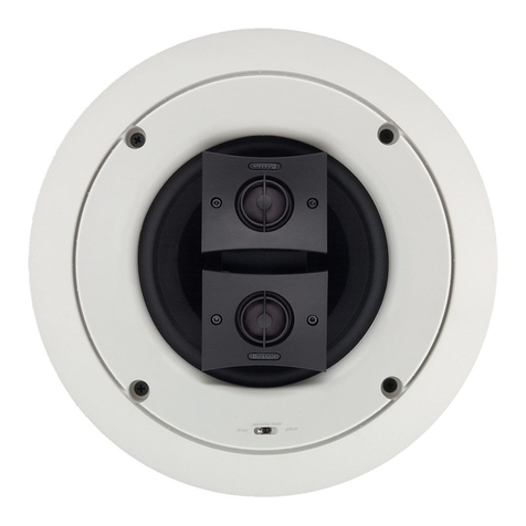
HSi 455W2
2-Way Dual 5¼” In-Wall Speaker
Magnetic grilles for
easy installation
Reduced Bezel Design for seamless
integration with the wall or ceiling
Single Speaker Stereo
ic grilles for
tic
stallation
s
ling
n with the wall or
r ceil
atio
n
Key features
r#PTUPOEFTJHOFEUXFFUFSTGPSDSZTUBMMJOF
high-frequency sound
r"EWBODFE#PTUPOXPPGFSTGPSNPSF
bass from less amplier power
r &BTZJOTUBMMGFBUVSFTGPSFYJTUJOH
walls or ceilings
r 1BJOUSFBEZTVSGBDFBMMPXTZPVUP
match your wall or ceiling nish
Cover Plates
New Construction Brackets
Optional Accessories
Fire Rated Back Boxes
3-Way LCR 2-Way LCR

HSi 250
2-Way 5¼”In-Ceiling Speaker
HSi 460
2-Way 6”In-Ceiling Speaker
(6” driver in a 5¼” cutout)
HSi 255
2-Way 5¼” In-Wall Speaker
HSi 455
2-Way 5¼” In-Wall Speaker
HSi 270
2-Way 6½”In-Ceiling Speaker
HSi 470
2-Way 6½”In-Ceiling Speaker
HSi 275
2-Way 6½” In-Wall Speaker
HSi 475
2-Way 6½” In-Wall Speaker
HSi 480
2-Way 8”In-Ceiling Speaker
HSi 485
2-Way 8” In-Wall Speaker
What it means to be
from Boston
First and foremost, Boston is an engineering
company, and every Boston system is optimized
to meet the highest performance standards (our
own). Of course, performance is only one measure
of value. So we’re careful to build all our products
with strict attention to everything from the choice
of materials to the details of t and nish. It’s how
we’ve been exceeding the expectations of serious
listeners for more than thirty years.
bostonacoustics.com
8”6½”5¼”

300 Jubilee Drive, Peabody, MA 01960 bostonacoustics.com
© 2008 All rights reserved. Boston, Boston Acoustics, and BassTrac are registered trademarks, and the B/A ellipse symbol and Play Smart are trademarks of Boston Acoustics, Inc.
300 Jubilee Drive, Peabody, MA 01960 bostonacoustics.com
© 2009 All rights reserved. Boston, Boston Acoustics, Deep Channel, and Kortec are registered trademarks, and the B/A ellipse symbol and Play Smart are trademarks of Boston Acoustics, Inc.
HSi 250 HSi 270 HSi 460 HSi 470 HSi 480
2-Way In-Ceiling Speaker 2-Way In-Ceiling Speaker 2-Way In-Ceiling Speaker 2-Way In-Ceiling Speaker 2-Way In-Ceiling Speaker
FREQUENCY RESPONSE (±3dB) 75Hz-20kHz 65Hz-20kHz 58Hz-20kHz 54Hz-20kHz 45Hz-20kHz
RECOMMENDED AMPLIFIER POWER 10-90 watts 10-90 watts 10-100 watts 10-100 watts 10-125 watts
TWEETER ¾” (20mm) ¾” (20mm) Pivoting ¾” (19mm) Pivoting 1” (25mm) Pivoting 1” (25mm)
Kortec® Soft Dome Kortec® Soft Dome Kortec® Soft Dome
WOOFER 5¼” (135mm) 6½” (165mm) 6” DCD™ Copolymer (152mm) 6½” DCD Copolymer (165mm) 8” DCD Copolymer (200mm)
EXTERNAL DIMENSIONS 8⁄” (205mm) diameter 10⁄” (262mm) diameter 8⁄” (205mm) diameter 10⁄” (262mm) diameter 12⁄” (329mm) diameter
MOUNTING HOLE CUTOUT 6¾” (171mm) diameter 8⁄” (225mm) diameter 6¾” (171mm) diameter 8⁄” (225mm) diameter 10⁄” (276mm) diameter
MOUNTING DEPTH (FROM SURFACE) 3⁄” (78mm) 4” (100mm) 4¼” (108mm) 4¾” (121mm) 5” (127mm)
HSi 255 HSi 275 HSi 455 HSi 475 HSi 485
2-Way In-Wall Speaker 2-Way In-Wall Speaker 2-Way In-Wall Speaker 2-Way In-Wall Speaker 2-Way In-Wall Speaker
FREQUENCY RESPONSE (±3dB) 75Hz-20kHz 65Hz-20kHz 65Hz-20kHz 52Hz-20kHz 45Hz-20kHz
RECOMMENDED AMPLIFIER POWER 10-90 watts 10-90 watts 10-100 watts 10-125 watts 10-150 watts
TWEETER ¾” (20mm) ¾” (20mm) 1” (25mm) 1” (25mm) Kortec 1” (25mm) Kortec
Kortec® Soft Dome Kortec® Soft Dome Kortec® Soft Dome
WOOFER 5¼” (135mm) 6½” (165mm) 5¼” Copolymer (152mm) 6½” DCD Copolymer (165mm) 8” DCD Copolymer (200mm)
EXTERNAL DIMENSIONS 10⁄ x 7½”(257 x 191mm) 11⁄ x 8⁄”(294 x 224mm) 10⁄ x 7½” (257 x 191mm) 11⁄ x 8⁄” (294 x 224mm) 13⁄ x 10⁄” (340 x 262mm)
MOUNTING HOLE CUTOUT 8⁄ x 6” (228 x 152mm) 10 x 7⁄” (254 x 187mm) 8⁄ x 6” (227 x 152mm) 10 x 7⁄” (254 x 187mm) 11⁄ x 8⁄” (300 x 226mm)
MOUNTING DEPTH (FROM SURFACE) 2⁄” (60mm) 3” (76mm) 2⁄”(73mm) 3½”(89mm) 3⁄”(97mm)
HSi 4830 HSi 455W2 HSi 460T2 HSi 470T2 HSi 475T2
3-Way In-Ceiling Speaker 2-Way In-Wall Speaker Stereo In-Ceiling Speaker Stereo In-Ceiling Speaker Stereo In-Wall Speaker
FREQUENCY RESPONSE (±3dB) 48Hz-20kHz 65Hz-20kHz 75Hz-20kHz 60Hz-20kHz 52Hz-20kHz
RECOMMENDED AMPLIFIER POWER 10-100 watts 10-125 watts 10-70 watts 10-90watts 10-125 watts
TWEETER 1” (25mm) 1” (25mm) Dual ¾” (20mm) Dual 1” (25mm) Dual 1” (25mm)
Kortec® Soft Dome Kortec® Soft Dome Kortec® Soft Dome Kortec® Soft Dome
MIDRANGE 3½” (89mm) — — — —
Stamped steel copolymer
WOOFER 8” (200mm) Dual 5¼” (135mm) 6” (152mm) 6½” (165mm) 6½” (165mm)
DCD Copolymer cast Copolymer DCD Copolymer DCD Copolymer DCD Copolymer
EXTERNAL DIMENSIONS 12⁄” (321mm) diameter 15⁄ x 9” (397 x 229mm) 8⁄” (205mm) diameter 10⁄”(262mm) diameter 11⁄ x 8⁄” (294 x 224mm)
MOUNTING HOLE CUTOUT 10⁄” (276mm) diameter 14¼ x 7⁄” (361 x 193mm) 6¾” (171mm) diameter 8⁄” (225mm) diameter 10 x 7⁄” (254 x 187mm)
MOUNTING DEPTH (FROM SURFACE) 6” (153mm) 2¾”(70mm) 4¼” (108mm) 4⁄” (115mm) 3½” (89mm)
Specications

This symbol found on tpe product indicates that the product must not be disposed of with household waste. Instead, it
may be placed
in
a separate collection facility for electronic waste
or
returned to a retailer when purchasing similar
product. The producer paid to recycle this product. Doing this contributes to reuse and recycling, minimizes adverse
effects
on
the environment and human health and avoids any fines for incorrect disposal.
Este sfmbolo que encuentra en el producto, indica que este producto no debe ser desechado en el cesto de basura
domestica.
En
su Iugar, debera ser depositado en forma separada y
en
depositos destinados a esta clase de desechos
electr6nicos o devueltos a su proveedor con el que regularmente adquiere productos similares.
El
fabricante pagara par
el reciclado de este producto. Hacienda esto contribuimos al rehuso y reciclado minimizando de esta forma los efectos
adversos
al
media ambiente, a Ia salud de las personas y previniendo el incorrecto desecho.
Ce symbole une fois sur le produit indique que celui-ci
ne
doit pas etre jete avec les dechets menagers.
Au
contraire,
il
doit etre place dans un lieu separe collectant les dechets electroniques, ou retourne au lieu de vente lorsque vous
achetez un produit similaire.Le fabricant finance le recyclage de ce produit. Ainsi, en incitant a
Ia
reutilisation ou au
recyclage, les effets negatifs sur l'environement et
Ia
sante publique sont minimises, et tout risque de poursuite du client
pour non-respect
de
Ia
legislation sur les dechets est evite.
II
simbolo sui prodotto indica che il prodotto stesso non pub essere smaltito gettandolo semplicemente fra i rifiuti
domestici. Esse deve essere smaltito in una struttura abilitata alia raccolta di apparati elettronici oppure, se viene
sostituito da un altro apparecchio similare, deve essere consegnato al negoziante presso cui si effettua il nuovo acquisto.
II
costruttore ha gia pagato per
il
riciclo di questa prodotto. Seguendo queste raccomandazioni contribuirete a recuperare
e riciclare, minimizzando l'impatto nocivo dei rifiuti sulla
naturae
sulla salute pubblica. Eviterete inoltre il rischio di
essere multati per una incorretta procedura di smaltimento.
Dieses Symbol, welches sich auf dem Produkt befindet, zeigt an, daB das Produkt nicht mit dem Hausmull entsorgt
werden dart. Stattdessen sollte es in einen separaten Sammelbehalter
fUr
elektronische Gerate, oder zu einem
Einzelhandler zuruckgebracht werden, bei welchem man ahnliches Produkt kauft. Der Hersteller ubernimmt
in
diesem
Fall die Kosten der Beseitigung. Diese vorgehensweise tragt zur Wiederverwendung und zur Wiederverwertung bei,
setzt schadliche Wirkungen auf das Klima und die menschliche Gesundheit herab und vermeidet mogliche Geldstrafen
fUr
falsche Entsorgung.
Symbolen sam aterfinns pa produkten betyder att varan inte far kastas med hushallsavtall. Vid kassering maste
produkten overlamnas till de faciliteter sam din kommun erbjuder for atervinning av hemelektronik eller till den aterforsal-
jare dar produkten inhandlats. Producenten
har
betalat for denna atervinningshantering. Genom att folja dessa regler
bidrar du sam konsument till en effektiv atervinning och minimerar negativa effekter pa miljon och var halsa samt
undviker boter for oriktig hantering
av
miljofarligt avtall.
Ce symbole une fois sur
le
produit indique que celui-ci
ne
doit pas etre jete avec les dechets menagers. Au contraire, il
doit etre place dans un lieu separe collectant les dechets electroniques, ou retourne au lieu de vente lorsque vous
achetez un produit similaire.Le fabricant finance le recyclage de ce produit. Ainsi, en incitant a
Ia
reutilisation ou au
recyclage, les effets negatifs sur l'environement et
Ia
sante publique sent minimises, et tout risque de poursuite du client
pour non-respect de
Ia
legislation sur les dechets est evite.
Boston
Boston
Acoustics
300 Jubilee Drive
Peabody,
MA
01960 USA
bostonacoustics.com
978-538-5000 ®
Copyright
2006.
All
rights
reserved. 142-002519-0

Boston
acoustics®
ATTN: PRODUCT REGISTRATION
BOSTON ACOUSTICS INC
300
JUBILEE
DR
PEABODY
MA
01960-4030
111
••••••
111.1
•••
11
••
11
••••
1
••
111
•••••
11.11
•••
11
•••
11
•••
1
•••
11
Postage
Required
Post Office will
not deliver
without proper
postage.

™ Boston
Acoustics•
Product Registration
for
U.S. and Canada purchases only.
BOStOn
Thank you for purchasing a Boston Acoustics product. Your feedback will help us to continue providing
acoustics•
consumers with the best possible products and service. Data provided
Is
the
confidential property
of
BostonAcoustics, Inc. and
Is
not
distributed
or
sold
to
third parties.
Please print below,
or
register your new product online at: bostonacoustics.com/prodreg
First Name
________________________________________
_ Last Name
______________________________________________
__
StreetAddffiss
________________________________________________________________________
_
Apt.#
______
_
Cicy
________________________________________________________
_ State
________
_
ZIP----------
E-mail---------------------------------------------------------------------------
Phone
____________
_
Age Group: Under
20
20 to 29
30
to
39
40
to
49
50
to 59
60
to
69
70
to
79
80 and over
Marital Status: Single _ Married Gender: Male Female
Education: High
School_
Some
College_
Associate/Jr. College
Degree_
4-Year College
Degree_
Graduate School
What
cype
ofBoston Acoustics product did you purchase? Home Stereo/Theater Car ln-WaiUin-Ceiling _ Multimedia/PC
Date ofPurchase
--------"'--------"'------
ModeiName
_________________
Serial#
____________________________________
_
(Located
on
a silver label
on
the
outside
of
packaging.)
Store Name
---------------------------------------------------
Cicy
-----------------------------
State
___
_
How did you hear about this product? Boston Acoustics advertisement Store salesperson _ Store advertisement Magazine review _
Store
display_
Online review _ Trade
show_
PC
manufacturer_
Friend/family _
Other
----------------------------------------------------------------------
What other brand(s) and model(s) did
you
consider when making this purchase?
Bffind(s)
_____________________________________________
__
Model(s)
___________________________________________
_
Thank
you
for
completing
this
form.
If
you
have any technical questions
or
are interested
in
other BostonAcoustics products,
visit
us
on
the
Web at bostonacoustics.com,
or
call (978) 538-5000.
C2007
Boston
Acoustics, Inc.
All
Rights
Reserved.
142-001601-3
This manual suits for next models
4
Table of contents
Other Boston Speakers manuals

Boston
Boston MCS 95 User manual

Boston
Boston HSi H460T2 User manual

Boston
Boston Micro130x User manual

Boston
Boston HPS 10HO User manual

Boston
Boston SC60 User manual

Boston
Boston SC55 User manual

Boston
Boston VRI585T2 User manual

Boston
Boston SC65 User manual

Boston
Boston VRi585 User manual

Boston
Boston Designer DSi485 User manual

Boston
Boston PRO50 User manual

Boston
Boston CS 270 User manual

Boston
Boston TVee One User manual

Boston
Boston SoundWare User manual

Boston
Boston Loudspeaker User manual

Boston
Boston i-DS3 User manual

Boston
Boston SR55 User manual

Boston
Boston HSi H460T2 User manual

Boston
Boston MC200Air User manual

Boston
Boston i-DS3 plus User manual