Boulder 2020 User manual


Boulder 2020
Advance D/A Converter
Owners Manual
V1.2 8/1/98

TABLE OF CONTENTS
GETTING STARTED
Placement of your 2020 D/A Converter . . . . . . . . . . . . . . . . . . . . . . . . . . . . . . . . . . . . . . . .1-1
Connecting the Power Supply to the Main Chassis . . . . . . . . . . . . . . . . . . . . . . . . . . . . . . .1-2
Connecting to the Mains Outlet . . . . . . . . . . . . . . . . . . . . . . . . . . . . . . . . . . . . . . . . . . . . . . .1-3
Connecting a Hardwire Digital Audio Source . . . . . . . . . . . . . . . . . . . . . . . . . . . . . . . . . . .1-4
Connecting an Optical Digital Audio Source . . . . . . . . . . . . . . . . . . . . . . . . . . . . . . . . . . . .1-5
Connecting to a Balanced Input Preamplifier . . . . . . . . . . . . . . . . . . . . . . . . . . . . . . . . . . . .1-6
Polarity . . . . . . . . . . . . . . . . . . . . . . . . . . . . . . . . . . . . . . . . . . . . . . . . . . . . . . . . . . . . . . . . . . . .1-6
Connecting to an Unbalanced Input Preamplifier . . . . . . . . . . . . . . . . . . . . . . . . . . . . . . . .1-7
Connecting to an Analog Recording Device . . . . . . . . . . . . . . . . . . . . . . . . . . . . . . . . . . . . .1-8
OPERATION
Powering Up . . . . . . . . . . . . . . . . . . . . . . . . . . . . . . . . . . . . . . . . . . . . . . . . . . . . . . . . . . . . . . .2-1
Input Selections . . . . . . . . . . . . . . . . . . . . . . . . . . . . . . . . . . . . . . . . . . . . . . . . . . . . . . . . . . . . .2-2
Display . . . . . . . . . . . . . . . . . . . . . . . . . . . . . . . . . . . . . . . . . . . . . . . . . . . . . . . . . . . . . . . . . . . .2-3
Advance . . . . . . . . . . . . . . . . . . . . . . . . . . . . . . . . . . . . . . . . . . . . . . . . . . . . . . . . . . . . . . . . . . .2-4
Digital Maximum Indication . . . . . . . . . . . . . . . . . . . . . . . . . . . . . . . . . . . . . . . . . . . . . . . . . .2-7
REMOTE CONTROL
Expansion . . . . . . . . . . . . . . . . . . . . . . . . . . . . . . . . . . . . . . . . . . . . . . . . . . . . . . . . . . . . . . . . . .3-1
Batteries . . . . . . . . . . . . . . . . . . . . . . . . . . . . . . . . . . . . . . . . . . . . . . . . . . . . . . . . . . . . . . . . . . . .3-5
Operation . . . . . . . . . . . . . . . . . . . . . . . . . . . . . . . . . . . . . . . . . . . . . . . . . . . . . . . . . . . . . . . . . .3-6
GETTING
STARTEDOPERATION
REMOTE
CONTROL
PROGRAM-
MING
REMOTE
PROGRAMMING
RECORDINGAPPENDIX

PROGRAMMING
Program Mode . . . . . . . . . . . . . . . . . . . . . . . . . . . . . . . . . . . . . . . . . . . . . . . . . . . . . . . . . . . . . .4-1
Inputs . . . . . . . . . . . . . . . . . . . . . . . . . . . . . . . . . . . . . . . . . . . . . . . . . . . . . . . . . . . . . . . . . . . . .4-2
Advance Parameter . . . . . . . . . . . . . . . . . . . . . . . . . . . . . . . . . . . . . . . . . . . . . . . . . . . . . . . . . .4-3
Digital Maximum Indication . . . . . . . . . . . . . . . . . . . . . . . . . . . . . . . . . . . . . . . . . . . . . . . . . .4-4
Master Reset . . . . . . . . . . . . . . . . . . . . . . . . . . . . . . . . . . . . . . . . . . . . . . . . . . . . . . . . . . . . . . . .4-5
PROGRAMMING FROM THE REMOTE CONTROL
Inputs . . . . . . . . . . . . . . . . . . . . . . . . . . . . . . . . . . . . . . . . . . . . . . . . . . . . . . . . . . . . . . . . . . . . .5-1
Advance Parameter . . . . . . . . . . . . . . . . . . . . . . . . . . . . . . . . . . . . . . . . . . . . . . . . . . . . . . . . . .5-2
Digital Maximum Indication . . . . . . . . . . . . . . . . . . . . . . . . . . . . . . . . . . . . . . . . . . . . . . . . . .5-2
USING A DIGITAL AUDIO RECORDER
Connections . . . . . . . . . . . . . . . . . . . . . . . . . . . . . . . . . . . . . . . . . . . . . . . . . . . . . . . . . . . . . . . .6-1
Main Out Connection . . . . . . . . . . . . . . . . . . . . . . . . . . . . . . . . . . . . . . . . . . . . . . . . . . . . . . . .6-1
Record Out Connection . . . . . . . . . . . . . . . . . . . . . . . . . . . . . . . . . . . . . . . . . . . . . . . . . . . . . .6-2
Record Source Selection . . . . . . . . . . . . . . . . . . . . . . . . . . . . . . . . . . . . . . . . . . . . . . . . . . . . . .6-2
Programming for Recording . . . . . . . . . . . . . . . . . . . . . . . . . . . . . . . . . . . . . . . . . . . . . . . . . .6-3
APPENDIX
Block Diagram . . . . . . . . . . . . . . . . . . . . . . . . . . . . . . . . . . . . . . . . . . . . . . . . . . . . . . . . . . . . . .7-1
Specifications . . . . . . . . . . . . . . . . . . . . . . . . . . . . . . . . . . . . . . . . . . . . . . . . . . . . . . . . . . . . . . .7-2
Troubleshooting . . . . . . . . . . . . . . . . . . . . . . . . . . . . . . . . . . . . . . . . . . . . . . . . . . . . . . . . . . . . .7-4
Notes . . . . . . . . . . . . . . . . . . . . . . . . . . . . . . . . . . . . . . . . . . . . . . . . . . . . . . . . . . . . . . . . . . . . . .7-5
GETTING
STARTEDOPERATION
REMOTE
CONTROL
PROGRAM-
MING
REMOTE
PROGRAMMING
RECORDINGAPPENDIX

GETTING STARTED
PLACEMENT OF YOUR 2020 D/A CONVERTER
Your Boulder 2020 is designed to reduce interference from external mag-
netic and radio fields (RF). While placement is not critical, known magnetic
fields should be avoided. Line of sight from the listening position is necessary
for the remote control to function properly.
Because the converter and its power supply are heavy, a solid, stable sur-
face should be used. As both will generate some heat, they should be allowed
to have good air circulation around them. In particular, make certain that the
fins on the rear of the supply are not blocked.
You may want to have some access to the rear panels for cable changes.
1-1 GETTING
STARTED

CONNECTING THE POWER
SUPPLY TO THE MAIN CHASSIS
Your Boulder 2020 Converter is sup-
plied with a Boulder 2000 Triple Power
Supply. Each of the three supplies is
independent of the others except for the
front panel LED which confirms correct
power supply operation of all three sup-
plies.
Three cables are provided for con-
necting the power supply to the main
chassis. Two of these cables have 4 pin
connectors and are used for connecting
the left and right audio supplies (±27V).
The third one has 5 pin connectors and
is used for the digital supplies (+5V).
Care must be taken not to confuse
these as any attempt to insert the wrong connector will result in a damaged
connector.
CAUTION: Connect and disconnect these cables only with the power sup-
ply turned off.
1-2 GETTING
STARTED

CONNECTING TO THE MAINS OUTLET
Your 2000 Power Supply is supplied with a mains cord suitable to the loca-
tion where it was purchased.
One of the features of the 2000 is its universal automatic voltage-selecting
power supply. Simply plug it into any standard outlet. (Exact voltage and fre-
quency compatibility is stated in the specifications section.)
1-3 GETTING
STARTED

CONNECTING AHARDWIRE
DIGITALAUDIO SOURCE
Four balanced AES/EBU digital
audio inputs are provided on the rear
panel of the main chassis. Each input
may be converted to unbalanced 75Ω
coax by the use of a Boulder
Digital Input Adapter. This adapter has
a special internal network to properly
terminate the cable, and must not be
confused with one made for analog
audio.
Connect each source to one of the
four inputs provided. Later, you will be
able to name each input with the
source’s name, so you might want to
make a list as you connect them.
1-4 GETTING
STARTED
ST Glass Input #5
AES/EBU Input #1
Toslink Input #6
AES/EBU Input #4

CONNECTING AN OPTICAL DIGITAL AUDIO SOURCE
Two optical inputs are also provided on the main chassis– a glass fiber con-
nection known as “ST Glass” and a plastic fiber known as “Toslink.” Remove
the protective caps before trying to insert the connector. (Store the caps in a
safe place.)
The “ST Glass” input will be selected as input 5, and the “Toslink” input
will be selected as input 6. Again, keep track of what sources you connect
because you will be able to name them later.
1-5 GETTING
STARTED

CONNECTING TO ABALANCED
INPUT PREAMPLIFIER
Because your 2020 Converter’s bal-
anced output has a very low output
impedance, any practical distance
between converter and preamplifier will
not be a problem.
The Boulder series Balanced Cables
will give the best possible sonic
connection.
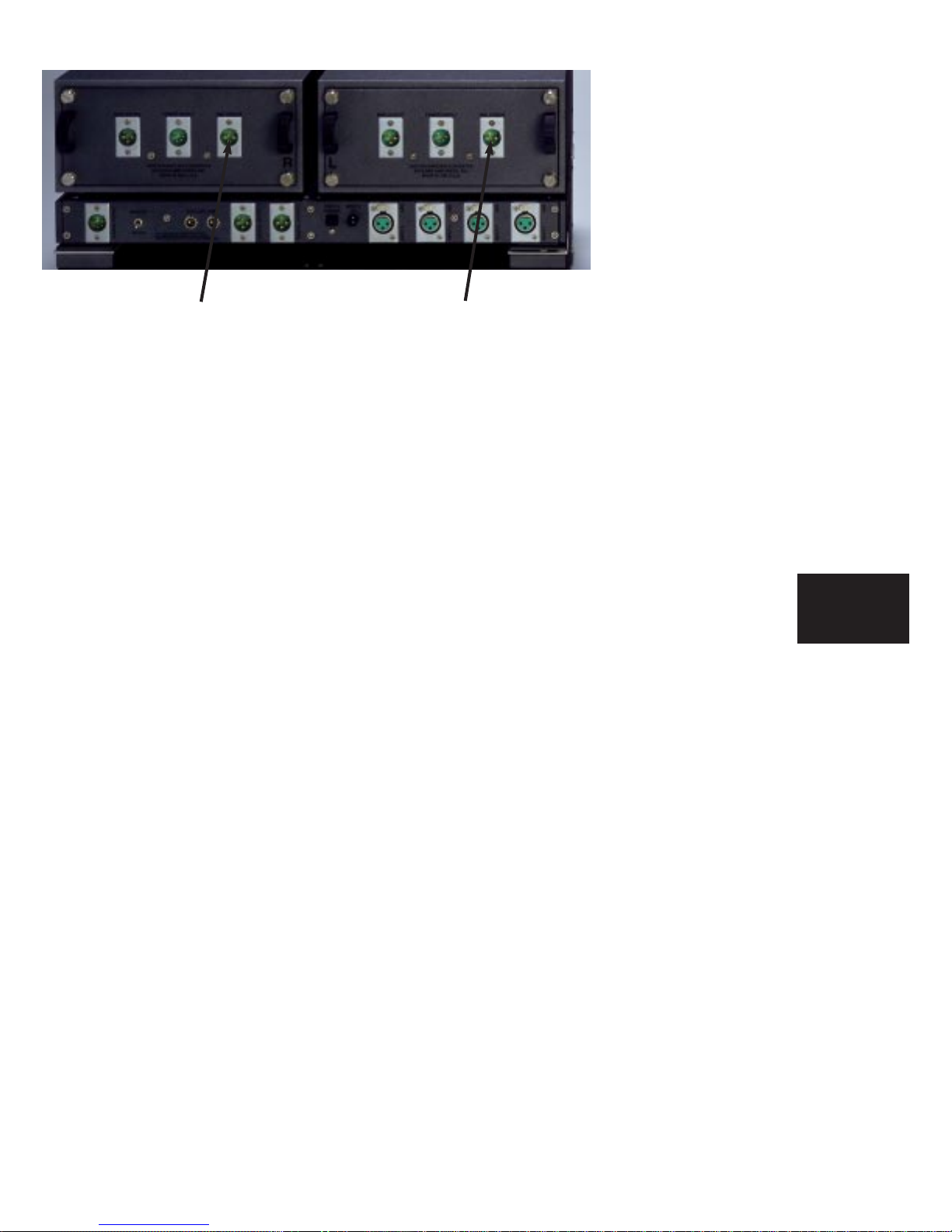
Connect each of the 2020’s outputs
marked “MAIN OUTPUT” on the chan-
nel audio assemblies to the inputs on
your preamplifier.
POLARITY
Please note that your Boulder 2020 Converter conforms to the new stan-
dard of pin 2 as the high or hot pin for all balanced outputs.
1-6 GETTING
STARTED
Right Main Output Left Main Output

CONNECTING TO AN UNBALANCED INPUT PREAMPLIFIER
The Boulder series Output Adapting Cables may be used to connect
the balanced converter outputs to an unbalanced preamplifier input. This
cable connects pin 1 to the shield and pin 2 to the center pin. It leaves the out-
put pin 3 unconnected.
If another brand of cable is used, be certain that this same electrical connec-
tion is made. Connecting the unused output pin (usually pin 3) to ground will
cause excessive ground currents and degrade performance. Use an ohmmeter
or continuity checker to determine how a cable is wired.
1-7 GETTING
STARTED
CONNECTING AN ANALOG
RECORDING DEVICE
If desired, the “REC OUTPUT” on
each channel audio assembly may be
connected directly to a recording device,
thus bypassing a preamplifier. This out-
put will always have the same digital
source as the main output.
1-8 GETTING
STARTED
Right Analog Record Output Left Analog Record Output

OPERATION
POWERING UP
With all your connections made, you are ready to listen to your Boulder
2020 Converter.
Push on the upper portion of the rocker switch on the rear panel of the
2000 Triple Power Supply. The indicator on the supply will first turn red, then
amber.
The indicator will be amber during normal operation. If for any reason,
any of the power supplies’ voltages are low, the indicator will change to red.
During the powerup sequence, “Boulder” and then “2020” will slowly
appear in the display window.
The front panel power switch can later be used for everyday turn on and
off. This switch mutes the audio, turns off the display, and puts the converter
in a standby mode.
2-1 OPERATION
INPUT SELECTIONS
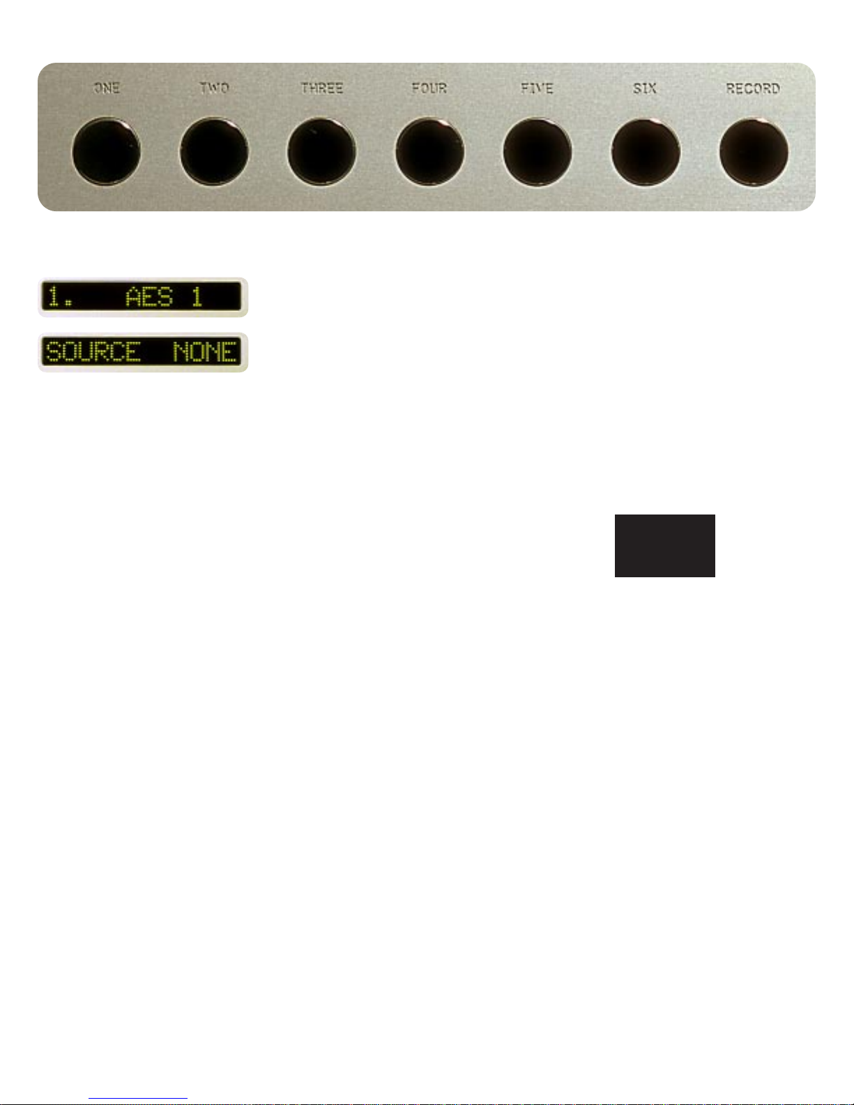
Select an input by pressing one of the pushbuttons labeled ONE through
SIX. The respective input will be displayed in the display and that signal will
be routed to the audio assemblies outputs. For example, if input one is chosen,
“1. AES 1” will show in the display.
Holding down any of the pushbuttons labeled ONE through SIX for sever-
al seconds will cause no input to be selected, and “SOURCE NONE” will show
in the display.
2-2 OPERATION

DISPLAY
The display brightness may be set to any of 8 brightness levels and also
completely off.
To change the brightness level, press the DISPLAY pushbutton. “DISPLAY
8” will show in the display. Continue pressing the DISPLAY pushbutton until
the desired brightness is obtained such as “DISPLAY 6.” The number in the
display will reflect the relative brightness.
After several seconds of not changing the brightness level, the display will
return to the source indication.
With the display at a brightness less than that of 8, any operation of a
pushbutton will cause the display to go to full brightness for several seconds,
and then return to the desired brightness. This ensures that if a function is
changed, it will be noticed whether intentional or inadvertent.
2-3 OPERATION

ADVANCE
Your 2020 Converter features an advance feature which actually moves one
channel (left or right) in time relative to the other channel.
There are several uses for this feature.
One use is to correct for listening positions which are off-center. Perhaps a
favorite chair or desk is placed to one side. Or if your main listening position
is in the center of a couch, you might like to recline at one end of the couch
from time to time.
Another is a difficult listening room where certain objects or walls prevent
the speakers from being placed equidistant from the main listening position.
While some correction for these problems can be made using only a bal-
ance control on a preamplifier, the ultimate solution is to use that balance con-
trol together with the time advance feature. The 2020’s advance feature works
in time similar to the way a balance control works in level.
When we speak of advancing a channel, say the left channel, it means that
we are sending the audio signal to the left speaker sooner than to the right
speaker.
The effect is as though someone is moving the left speaker closer to the lis-
tener, making it seem more prominent if you are sitting in the physical center.
If you are sitting to the right as the left channel is advancing, the soundstage
will seem to come around to a more natural feeling.
2-4 OPERATION

Let us assume that “INCHES” is chosen as the units of advance. To
advance the left channel, press the LADVANCE pushbutton. “ADV 0.00’’”
will show in the display. Holding down the L ADVANCE pushbutton will
cause increasingly higher numbers of advance until the button is released.
The advance can be further increased in the left channel or swept through 0
and then start advancing the right channel by use of the LADVANCE and R
ADVANCE pushbuttons. This works much like a balance control.
The ADVANCE pushbutton will turn on and off the advance without
changing the setting. The ADV CLEAR pushbutton will clear the setting to
zero.
Determining the correct amount of delay to use is possible to do by ear
with some practice. It is best to use a recording which has a strong mono con-
tent such as a single voice or instrument along with some accompaniment to
give a feeling of soundstage.
It also helps to have a rough idea of how much delay will work for a given
situation.
Let’s take the example of sitting 24 inches to the right of center. Assuming
that the two speakers and the center listening position form an equal sided tri-
angle, and that they are some 120 inches from the listener, a left advance of 23.7
inches would be correct. (This is a number very nearly that of the lateral offset
of the listener. So for small changes, a distance slightly less than the lateral off-
set can be used as a starting point.)
2-5 OPERATION
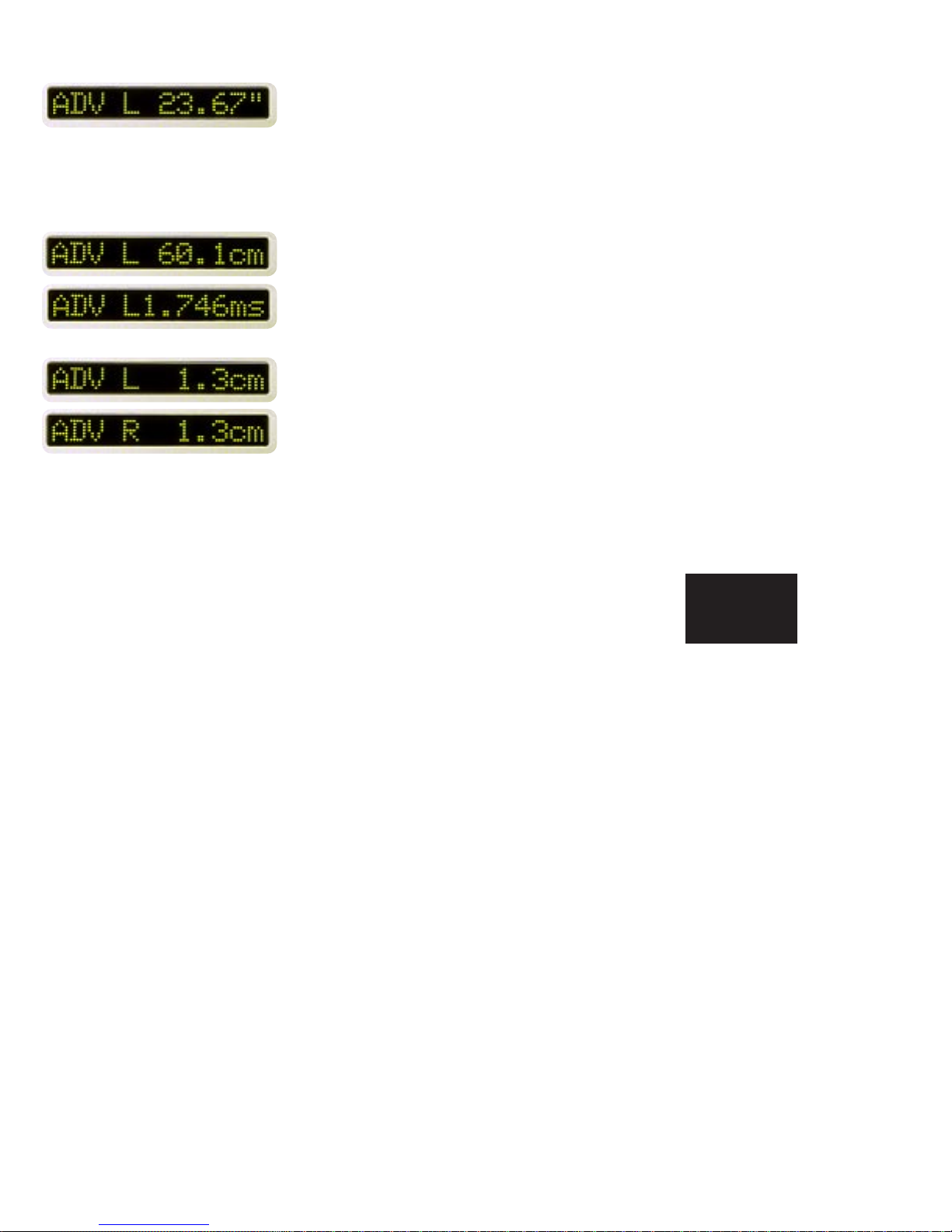
To verify this by listening, press the LADVANCE pushbutton until “ADV
L 23.67’’” appears in the display. Now by successive presses of the ADVANCE
pushbutton, the advance will be turned on and off as indicated by the display.
First try sitting in the center with the advance turned off. Listen to the
music and get a mental picture of the image. Then sit 24 inches to the right
and turn on the delay. The sound image will be very nearly that of the one first
heard in the center.
Nine advance times may be stored for later use. See the section on operat-
ing the remote control.
If you are using different advance units, then the display would read either
“ADV L 60.1cm” or “ADV L1.746 ms.”
To make only a small adjustment in the location of one speaker, clear the
advance feature by pressing the CLEAR pushbutton, and then use the L
ADVANCE and R ADVANCE pushbuttons to obtain small increments of
advance. Even small increments such as 1.3cm can make the soundstage
noticeably different.
2-6 OPERATION

DIGITAL MAXIMUM INDICATION
Analog sources have an inherent maximum voltage limit known as “clip-
ping.” Similarly, all digital sources have an inherent maximum numerical limit
in the recording process. A special circuit which detects that this limit was
reached is included in your Boulder 2020 D/AConverter.
If “DIG MAX ON” is selected in the programming mode, then “DIGITAL
MAX” will be displayed when the limit is detected.
2-7 OPERATION

REMOTE CONTROL
The remote control for your Boulder
2020 D/A Converter is in three sections–
the transmitter, the 2020 module and the
battery pack. These sections are held
together by long screws inserted into the
top of the transmitter and running
through all sections.
Additional longer screws are provid-
ed for adding sections from other
Boulder series 2000 products to make
one convenient control. A special screw-
driver designed to fit the end of the
screws is provided. The modules may
be assembled in any order desired.
When removing sections, it is impor-
tant to use the screws to maintain con-
nector alignment. DO NOT PULL THE SCREWS OUT FIRST.
To separate sections, loosen the screws while slowly pulling the battery
pack from the 2020 module. Slide the battery pack off the screws. Then slide
the module off the screws. Once all sections are removed from the transmitter,
you may remove the screws from the transmitter.
3-1 REMOTE
CONTROL
Transmitter
Battery Pack
2020 Module
Screws for
2 Modules
Table of contents
Popular Media Converter manuals by other brands


Thinklogical
Thinklogical VDA-1 product manual

ZENIC
ZENIC ForteVision FV-3000HS instruction manual

Peachtree Audio
Peachtree Audio t1 quick guide

Omnitron Systems Technology
Omnitron Systems Technology iConverter T1/E1 user manual

AJA
AJA KONA LHI Installation and operation guide

Baumer
Baumer Hubner Berlin microGen PMG10 EtherCAT operating manual


