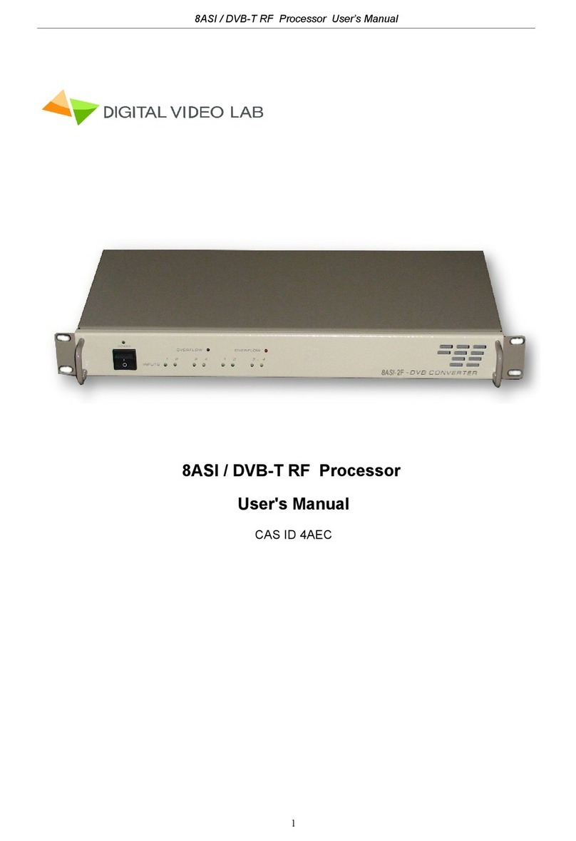
Digital Video Lab Processor 8ASI/DVB-S2 RF User manual

Processor 8ASI / DVB-T RF User’s Manual
1
Processor 8ASI / DVB-S2 (S) RF
CAS ID 4AEC
User's Manual

Processor 8ASI / DVB-S2(S) RF User’s Manual
2
Overview 3
Construction 4
Front Panel 4
Rear Panel 5
Main features 6
Specification 8
Connections 9
IP Out 11
Operation Common information 12
The System Installation 13
How to add the new Processor to the System 13
Server PC network parameters settings 14
DVCrypt SW operation 16
he new Processor Installation 19
RF Output settings 25
The Output Stream forming 27
IP Outputs Settings 28
Warranty 30

Processor 8ASI / DVB-T RF User’s Manual
3
Overview
The 8ASI DVB-S2 (S) Processor is a multifunction device intended for multichannel DVB-
S2 (S) broadcasting. It provides TS re-multiplexing, scrambling, modulating and Up-con-
verting.
· The processor re-multiplexes up to 8 input Transport Streams(TS) and forms a
spectrum in the DVB-S2(S) format transmitted at Radio frequency.
· Standard SD/ HD DVB-S2(s) receivers can be used as subscriber receivers.
· IP output can be used to transport one of the packages via IP network or monitor
one of the packages chosen from output or input stream at your PC.
The single Processor allows you to organize DVB-S broadcasting of ~8 programs,
as well as a system for monitoring of channels on your PC. The Processor can re-
place the remultiplexer, scramblers, DVB-S2 Modulator and UP-converters.
r

Processor 8ASI / DVB-S2(S) RF User’s Manual
4
Construction
The processor has a monblocking design –19`` REC mounted 1U
Contains the main board with the input and output connectors, power supply.
Front panel
The front panel Indicators:
1
Power
2
Power Indicator LED
3
LED Indicator
4
Indicator `s control button
INPUTS 1-8. Indication of the ASI stream at the relevant input.
I.
OVERFLOW - Built-in multiplexers has an indicator showing the maximum allowable
stream is exceeding.
This is due to the fact that the input streams typically have a variable bit rate, and at the
Processor settings time the forming steam may be correct, but during a broadcast time ei-
ther of the input streams may increase and cause spillage of the subscriber images. To
avoid this on the important channels, it is possible to assign one channel as the one that
may be subject to restrictions.

Processor 8ASI / DVB-T RF User’s Manual
5
Rear Panel
1.
In 1 –In 8 ASI inputs i
2.
Out, Out 2 - 2 ASI outputs
3.
RF Out. Radio Frequency output
4.
ETHERNET / IP Output RJ45 connector
5
FAN
6
Ground pole
7
AC 220V
8
Fuse

Processor 8ASI / DVB-S2(S) RF User’s Manual
6
Main features
8 ASI Inputs re multiplexing
Modes: DVB-S or DVB-S2
Output modulation QPSK or 8PSK
Software update/upgrade.
DVCrypt CAS support.
EPG, OTA, LCN support, Network Search.
Up to 92 PID
Adjustable level of the output RF signal.
Quick replacement of the device in the system without stream rescan
MPEG-2, MPEG-4/AVC, HD / SD and 3D support.
Automatic and manual PID insertion;
Connection to PC: Ethernet 100 Е-base, RJ45.
IP Output with Staffing Off function.
IP output: Supported protocols RTP, RTP+,UDP.
IP output can be used to transport one of the packages via IP network.
Visual monitoring the input and output streams with the free program DVCrypt Ts
Monitor via IP
IP allows you to record the output ASI stream to the PC for further analysis.
Quick replacement of the device in the system without stream rescan.

Processor 8ASI / DVB-T RF User’s Manual
7
Specification
INPUT INTERFACE
ASI Inputs
8 DVB ASI streams, 8 BNC Connectors
ASI OUTPUTS
2 DVB-ASI Outputs
2 DVB ASI, 2 port, 2 BNC Connectors
RF Output
Connector
F-type
Frequency range:
70-1700 MHz (adjustable)
Output RF signal level
80-100 dB/uV, adjustment -10dB/uV;
MODULATION
STANDARD
DVB-S /S2
Modulation type
QPSK/ 8PSK
Symbol Rate
6750 - 27500 ksym/s
Rolloff factor
0,2 ; 0,25 ; 0,35
IFFT-
2K
IP TS Output and Ethernet control
Ethernet type:
10/100 Base-T (RJ-45)
Format:
UDP/IP, RTP/IP
IP Address Format:
Multicast, Unicast
TS Bit rate:
0,5~60 Mbps
TS Packet format:
188 Byte
General
Power:
~220V+\-20%
Power Consumption:
Max 20W
Size:
19``, 1U 480*45*180 (mm)
Weight:
3,5 Kg

Processor 8ASI / DVB-S2(S) RF User’s Manual
8
Connections
AC In 220В50Hz+ Fuse
GND
Grounding Terminal
When connecting this unit to any other component, make sure that it is properly
grounded by connecting this terminal to an appropriate point. When connecting, use the
socket and be sure to use wire with a cross-sectional area of at least 1.0 mm.
ASI Inputs
“IN1 –IN8”
Input signals must comply with the EN 50083-
9:1998 standard.
ASI Outputs
2 ASI Outputs:
Each of this 2 outputs has the same ASI stream
RF Output.
F Connector. Frequency range 70-1700 MHz (adjustable)
IP Out
RJ45 connector for the IP Out and Ethernet Control

Processor 8ASI / DVB-T RF User’s Manual
9
Operation common information
Processor must be connected to the PC for the settings, control and Update and Upgrade.
(The rear panel RJ45 connector)
The Processors have built-in system time synchronization. The control computer is
synchronized from the source time signal and in turn synchronizes the Processor. The
processor provides a timing signal that is synchronized receiver. In case of loss of signal
synchronization whole system will work, but showing the wrong time. DVCrypt program will
write this in the server log.
Environment Requirement
Environment Temperature 5~40 (sustainable),0~45 (short time),
Installing air-conditioning is recommended
Power Requiring device power, air-conditioning power and lighting power are
independent to each other. Device power requires AC power 220V 50Hz. Please
carefully check before running.
Machine Hall Floor Electric Isolation, Dust Free, Ground anti-static material.
Grounding Requirement
Good grounding is the basis of reliability and stability of devices. Good grounding are the
most important guarantee of lightning arresting and interference rejection.
Coaxial cable’s outer conductor and isolation layer should keep proper electric conducting
with the metal housing of device.
Grounding conductor must adopt copper conductor in order to reduce high frequency
impedance, and the grounding wire must be as thick and short as possible.
It is prohibited to use any other device as part of grounding electric circuit
The area of the conduction between grounding wire and device’s frame should be no less than
25mm2.

Processor 8ASI / DVB-S2(S) RF User’s Manual
10
The System Installation.
To obtain a workable system, it is necessary:
1. Operating System: Windows XP, or Windows server 2003/2008.
2. DVCrypt program
3. HUB/switch for local area computer networks - for simultaneous connection of all the
Processors to a single computer.
RJ45 connector cable to the HUB connection:
RJ45
RJ45
1
white / orange
white / orange
1
2
orange
orange
2
3
white / green
white / green
3
4
blue
blue
4
5
white / blue
white / blue
5
6
green
green
6
7
white / brown
white / brown
7
8
brown
brown
8
4. One -by one connection of all processors to the server DVCrypt and register them in
the system. The system will automatically assign a number to the new Processor and
will monitors the numbers of all of the processor in the system.
How to add the new Processor to the System.
Attention! All connection to the PC is required to switched off power and grounded
equipment
1. Connect the Processor via the HUB or Switch to PC
2. Set the Server PC network parameters.
3. Install and run DVCrypt program
4. Click the “Processors”icon - appear the “Processors”window
5. Click the + icon and follow the wizard's instructions to install the Processor.
6. If all is OK and Processor is found, it will appear in the window" Processors ".
7. Double click the left mouse button on the number of the processor will open the Set-
tings window, where you must point the name of the channel fed to the Processor
inputs and the frequency at which the Processor operates.
8. Repeat steps 1-6 for all of the Processors.

Processor 8ASI / DVB-T RF User’s Manual
11
Server PC network parameters settings.
Server PC requirements:
please check that following requirements are met:
1CPU: 1 GHz or faster;
2RAM: 1 GB or more;
3HDD: at least 1 GB of free space;
4LAN adapter and/or USB for modules interface;
5Operating System: Windows XP, or Windows server 2003/2008.
Required PC setting:
The computer should be equipped with network adapter with installed TCP/IP.
Network adapter properties:
The computer IP address can be assigned statically or dynamically (DHCP).
As example IP address is 192.168.1.3 (shown at the Figure below).

Processor 8ASI / DVB-S2(S) RF User’s Manual
12
Wiring diagram is as follows:
If you need to have the Server with the other Computer in the network, we recommended
to use the other diagram, in order to provide reliable communication with the Processor
and additional security:

Processor 8ASI / DVB-T RF User’s Manual
13
DVCrypt SW operation
Software installation
Simply run the included DVCrypt_Install.exe installation file and follow the prompts.
Starting the Control Program
The Control Program is started from the Start menu. / All Programs / DVCrypt / Control
Program
When you start the program will require to choose the type of connection:
Locally, if the program Server installed on the same computer, or to a server, if it is in-
stalled on another PC. Then it is necessary to enter the IP address and port of the PC on
which you have installed the server.
After selecting the connection window will open system of administration "Login":
The program uses a system of administration which is structured as follows:
There is a main user of the DVCrypt program –Administrator. All rights to use these func-
tions (on / off) belong to the administrator.

Processor 8ASI / DVB-S2(S) RF User’s Manual
14
Administrator is enters to the program as an “administrator”with personal password and
appoints the other users. The administrator also can on / off some of the functions of the
program DVCrypt, necessary for the user.
The number of users and their rights determined by the administrator.
All default passwords is empty.
DVCrypt program contains two main functional modules. DVCrypt Client and DVCrypt
Server.
By clicking the Login button brings you to the DVCrypt Client main window:
The DVCrypt Server can by started from the taskbar.:
To open the DVCrypt Server log you can click left mouse button the Server Icon -
the Server Log Window appear.
To open the DVCrypt Server Settings click right moue button the Server Icon and
select Settings.
In the Server settings need to enable communication with the Processor - Ethernet:
If the Server has a single network adapter for communication with the Processor, it is rec-
ommended to enable the option “The network interface only”and point it IP address:

Processor 8ASI / DVB-T RF User’s Manual
15

Processor 8ASI / DVB-S2(S) RF User’s Manual
16
The new Processor Installation
1) Connect the new Processor to the HUB (RJ 45-RJ 45 cable) and HUB to the Server-PC.
(see page 15)
2) Turn on the Processor power.
3) In the DVCRypt Client Window (see page 17) left click icon
the DVCRypt Client -Modules window will opened.
444))) Left click the icon (Add new Module) -The “Add new
module”window is appear
5) Select connection type for new module - Ethernet):

Processor 8ASI / DVB-T RF User’s Manual
17
Click “Next”and follow the wizard prompts
NOTE!
New Device connected to the system will be searched, their MAC and IP addresses will be
listed. Search can be repeated by pressing Refresh button. If there are a few Devices, it is
difficult to determine the Device among others. In this case you can select the Device in
the list and press Blink button. The selected Device will flash red LED (built in Ethernet
connector) three times. Next step is entering IP address of selected Device.
Select the Processor (Module) and click next.
6) Next step is the IP address of the selected Processor setting.
Select any free IP address in the range of this local network (for example, we use ad-
dresses from 92.168.1.100 to 192.168.1.200) and enter it. Network mask and Default gate-
way should be set only if the Device will work in other subnetworks for the new Device and
add it to the system.

Processor 8ASI / DVB-S2(S) RF User’s Manual
18
The server will set the IP address for the new processor and add it to the system:
The IP address and MAC will be shown in Devices window in Control Software. It will be
impossible to change the Device IP address hereafter. To change the Device IP address it
is necessary to delete the Device from the system and add it again.

Processor 8ASI / DVB-T RF User’s Manual
19
After adding the Device it should be set. Double click on the Device number and it will ap-
pear Converter setting window,
Notes
If the distance between the Server and Devices is rather long and there are routers, and
automatic search doesn't work - in this case it is necessary to do the following:
Connect the new Device to the local network or to the Server directly and set the IP ad-
dress as described above. Not waiting that the system will find and add the Converter, in-
terrupt the adding procedure.
Connect the new Converter to remote network. Run adding procedure and select the op-
tion “The module is not listed here. Enter IP address of the module directly”
Enter IP address of the Processor (Module).

Processor 8ASI / DVB-S2(S) RF User’s Manual
20
The server will try to communicate with the Device and add it to the system:
This manual suits for next models
1
Table of contents
Other Digital Video Lab Media Converter manuals
