Bourns 1800 Series User manual

Features
■Low peak clamping voltage even during
severe current surges
■Ability to repeatedly protect against surge
currents in excess of 10,000 amperes
■Convenient mounting and grounding to any
flat surface or to Din 1 (TS-32) or DIN-3
(TS-35) rail
■Cable shields are passed through and
may be either grounded or not grounded at
the protector
■Vibration-proof screw-type clamp terminals
■Flame-resistant epoxy-filled housing
1800 Series – Signal and Dataline Protector
Specifications are subject to change without notice.
The device characteristics and parameters in this data sheet can and do vary in different applications and actual device performance may vary over time.
Users should verify actual device performance in their specific applications.
Bourns®Model 1800 Series Signal and Dataline Protectors are designed to protect sensitive electronic circuits and components from damaging
surge voltages and currents. Their extremely fast response and low clamping voltages make them particularly suitable for the protection of
signal and data lines associated with computer, data communication, instrumentation, broadcasting and industrial controls. They may be used
directly with EIA standard interfaces RS-232, RS-422, RS-423, RS-485 and with 20 mA and 50 mA instrumentation loops. The Model 1800
Series Signal and Dataline Protectors are fast, rugged and capable of protecting against fast rising voltage transients as well as the severe
current surges associated with lightning discharges.
Method of Operation
Bourns®Model 1800 Series are heavy-duty, multi-staged protectors. A solid-state section intercepts the leading edge of the surge with sub-
nanosecond response time. Within microseconds a 3-pole common chambered gas tube capable of handling 20,000 ampere lightning
currents operates and crowbars the surge to ground. The protector remains in the crowbar state until the surge has passed and line voltages
return to safe levels, then automatically restores the line to normal operation. There is no need for resetting a breakeror replacing a fuse.
Application
Protectors are generally placed at each end of a signal or data line or current loop. In the case of daisy-chain configurations (such as RS-485),
protectors are placed at each node. The 1820 models provide both line-to-ground and line-to-line protection and are designed to use on differ-
ential signals (such as RS-422 or RS-485) and 4-20 mA current loops. 1810 models provide line-to-ground protection for two separate circuits
and are designed for use on ground referenced signals (such as RS-232) where the return wire is grounded at the protector. The 1811 and 1821
models provide the same protection modes for high frequency applications.
Related Bourns®Protectors
For outdoor applications with 1/2 inch NPT ports (such as field-mounted 4-20 mA transmitters), please refer to Bourns®Model 1669 Series
Protector. In this application, the mixed use of a Model 1800 Series Protector at the controller and a Model 1669 Series Protector at the field is
recommended.
Characteristics @ 25 °C
Surge Life
>100 operations with 200 Amps....................................................................................................... 10 x 1000 μsec
>10 operations with 10,000 Amps.................................................................................................... 8 x 20 μsec
DC Leakage Current at Rated L/G Voltage ........................................................................................... <10 μAmps
Signal/Data Attenuation at Maximum Data Rate ................................................................................... 3 db with 600 Ω termination
Operating Temperature.......................................................................................................................... -40 ºC to + 60 ºC
Response Time...................................................................................................................................... 50 pico-seconds
Wire Size ............................................................................................................................................... 22-14 AWG
INTERFACE OPERATING
CHARACTERISTICS
Peak Max.
Signal Data
Voltage Rate
L/L L/G
BASE
MODEL
NUMBER
(see below
for Clamp
designation)
PROTECTIVE CHARACTERISTICS
Peak Clamping Voltages LOAD
CURRENT
TYPICAL
CAPACITANCE
L/G L/L
SERIES
RESISTANCE
Each Line L/L
(Input to output)
@ 5000 Amps,
8x20 μsec
Surge and Voltage
Rate-of-Rise of
100 kV / μsec
L/L L/G
@ 1000 Amps,
8x20 μsec
Surge and Voltage
Rate-of-Rise of
500 V / μsec
L/L L/G
(Volts) (Volts) (MHz) (Volts) (Volts) (Volts) (Volts) (mA) (pF) (pF) (Ohms)
20 10 10 1810-10-XX 50 25 42 21 220 2200 1200 10
10 10 4 1820-10-XX 25 25 21 21 220 3300 3300 10
20 10 50 1811-10-XX 60 30 52 26 350 45 45 10
10 10 50 1821-10-XX 30 30 26 26 350 65 65 10
30 15 8 1810-15-XX 70 35 56 28 180 1500 750 15
15 15 3 1820-15-XX 35 35 28 28 180 2300 2300 15
30 15 45 1811-15-XX 80 40 64 32 300 45 45 15
15 15 45 1821-15-XX 40 40 64 32 300 65 65 15
56 28 9 1810-28-XX 110 55 90 45 150 1100 600 22
28 28 4 1820-28-XX 55 55 45 45 150 1800 1800 22
56 28 40 1811-28-XX 120 60 45 45 250 45 45 22
28 28 40 1821-28-XX 60 60 45 45 250 65 65 22
100 50 10 1810-50-XX 178 89 156 89 100 500 300 51
50 50 4 1820-50-XX 89 89 45 45 100 800 800 51

File No.
1800SERS3 P/N 1669
PROTECTOR
BOURNS
P/N 1820
BLK
RED
XMTR
/WHITE
/WHITE
GREEN
BLACK
RED
1669
BOURNS
+
-
CONTROL ROOM
I
I
SUPPLY
POWER
OHMS
250
1-5 VOLTS
RECEIVER
E2
E3
E1
L2
L3
L1
GND
COMMON
GND.
~
~
~
~
Typical Connections
Unbalanced Interface, Two Individual Circuits, Such as RS-233
REV. G 04/13
Specifications are subject to change without notice.
The device characteristics and parameters in this data sheet can and do vary in different applications and actual device performance may vary over time.
Users should verify actual device performance in their specific applications.
1800 Series – Signal and Dataline Protector
How To Order (Clamp)
Add -A1 to base model number for
DIN-1 clamp.
(Example: 1810-10-A1)
P/N 1810P/N 1810
~~
GND.
COMMON
AND/OR GND.
EQPT. COMMON
XMTR
GND
L1
L3
L2
E1
E3
E2 RCVR
RCVR
E2
E3
E1
L2
L3
L1
GND
XMTR
EQPT. COMMON
AND/OR GND.
COMMON
GND.
~~
BLDG. 1 BLDG. 2
Balanced or Differential Interface, Such as RS-422
P/N 1820
BLDG. 2BLDG. 1
RCVR
~
~~
~
E2
E3
E1
L2
L3
L1 GND
EQPT. COMMON
AND/OR GND.
COMMON
GND.
P/N 1820
GND.
COMMON
AND/OR GND.
EQPT. COMMON
XMTR
GND L1
L3
L2
E1
E3
E2
Current Loop, 4-20 mA
Grounding: The 8-32 mounting screw and attached clamp, and hence the DIN-1 (TS-32)
or DIN-3 (TS-35) rail, serve as the protector ground. The rail (or 8-32 mounting screw if the
clamp is not used) should be connected to the facility ground via an AWG #6 or larger copper
wire. This wire should be as short and straight as possible. Single point grounding will provide
better protection and will permit the protector to be located a distance from the equipment.
Product Dimensions
E3/L3 GROUNDING LINK
GND
EQPT
E2 E3 E1
LINE
L1 L3 L2
1.91
(48.51) .74
(18.80)
3.28
(83.31) PIN
ALIGNMENT 8-32UNF-2A
.375
(9.53)
.125
(3.18) .093
(2.36)
.70
(17.80)
DIMENSIONS: MM
(INCHES)
(TS-32/EN50035)
DIN-1 RAIL
GROUNDING SCREW
FEED-THRU(E3/L3)
(49.02)
(28.96)
1.14
1.93
(TS-35/EN50022)
DIN-3 RAIL
MOUNTING/GROUNDING SCREW
1.79
(45.47)
Add -A3 to base model number for
DIN-3 clamp.
(Example: 1810-10-A3)
DIMENSIONS: MM
(INCHES)
Other Bourns Surge Protector manuals
Popular Surge Protector manuals by other brands
Wychwood Audionics
Wychwood Audionics F3lite user manual

Patton electronics
Patton electronics 500 user manual
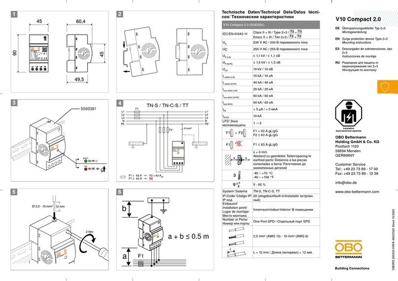
OBO Bettermann
OBO Bettermann V10 Compact 2.0 Mounting instructions
Panamax
Panamax M8-HT-PRO instruction manual
Eaton
Eaton PXL Series Installation and operation manual
Adcom
Adcom ACE-515 owner's manual
