BOXER AGRI DUO User manual

FRONT AND REAR MULCHER
DUO
USER MANUAL
P. de Heus en Zonen Greup B.V.
Stougjesdijk 153
3271 KB Mijnsheerenland
The Netherlands
Tel: +31 (0) 18 66 12 333
E-mail: info@boxeragri.nl

FRONT AND REAR MULCHER | User manual December 2020
ENG | ENGLISH
TRANSLATION OF THE ORIGINAL MANUAL

CONTENTS
December 2020FRONT AND REAR MULCHER | User manual
1. GENERAL INFORMATION ............................................................................................................ 4
1.1 Introduction ......................................................................................................................................... 4
1.2 Symbols ................................................................................................................................................ 4
2. SAFETY LABELS ........................................................................................................................... 5
3. SAFETY ....................................................................................................................................... 7
3.1 Allowed use .......................................................................................................................................... 7
3.2 Improper use ........................................................................................................................................ 7
3.3 Safety in the workplace........................................................................................................................ 7
3.4 General safety rules ............................................................................................................................. 8
4. OPERATION .............................................................................................................................. 10
4.1 Attachment to the tractor.................................................................................................................. 10
4.2 Driveline attachment.......................................................................................................................... 11
4.3 Working height adjustment ............................................................................................................... 12
4.4 Drive belt adjustment......................................................................................................................... 13
5. TRANSPORT .............................................................................................................................. 14
5.1 Working speed ................................................................................................................................... 14
5.2 Road transport ................................................................................................................................... 14
6. STORAGE .................................................................................................................................. 15
6.1 Pre-season check................................................................................................................................ 15
7. MAINTENANCE ......................................................................................................................... 16
8. PARTS LISTS .............................................................................................................................. 18
9. CE DECLARATION OF CONFORMITY .......................................................................................... 26

Page 4/26
FRONT AND REAR MULCHER | User manual December 2020
1. GENERAL INFORMATION
1.1 Introduction
The DUO Flails are primarily designed to mow grass, weeds and light brush.
The mowers are assembled for operation with 1000 RPM tractor input only (rated PTO up to 45 HP), and supplied
standard with Cat. I lift pins for tractor attachment.
The mowers can fit Cat. I quick attach hitch, by using suitable bushings to adapt diameters of lift pins.
1.2 Symbols
This booklet contains three "safety graphic symbols" which highlight the relevant danger levels or important
information:
WARNING
It draws the operator's attention to situations which can jeopardize people's safety.
CAUTION
It draws the attention to situations which jeopardize the machine efficiency but not people's safety.
IMPORTANT
It highlights general information which does not endanger people's safety or the efficiency of the parts.
Page 5/26
December 2020FRONT AND REAR MULCHER | User manual
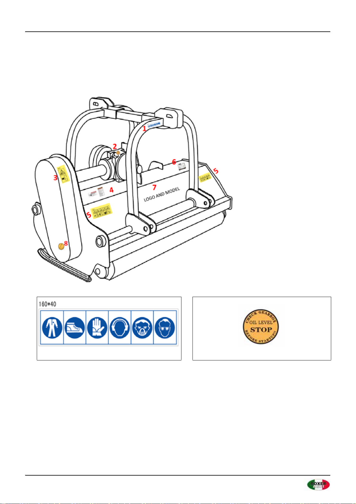
2. SAFETY LABELS
The safety labels and the information on the machine, listed in the following table, must be necessarily read and
respected; failure to follow these warnings can cause death or severe injuries. Make sure that the labels are always
present and legible, should this not be the case, contact your nearest dealer to replace the missing or illegible ones.
12

Page 6/26
FRONT AND REAR MULCHER | User manual December 2020
34
56
Logo and model
7
8

Page 7/26
December 2020FRONT AND REAR MULCHER | User manual
3. SAFETY
3.1 Allowed use
DUO flail mowers, as described in this instruction and maintenance booklet, have been specifically designed to mow
grass, weeds, and light brush up to 1" diameter. Any other use jeopardizes the operator's safety and the machine
integrity.
3.2 Improper use
The mower was designed to mow grass, weeds, and light brush only. Only operate this mower on a properly sized
and equipped tractor.
When using DUO flail mowers, it is particularly forbidden:
• The attachment to tractors of unsuitable power or weight.
• To use other than 1000 R.P.M. PTO speed.
• To work in excessively stony grounds.
• To work on excessive slopes.
• To approach the machine when wearing inappropriate work clothing.
• To get on the machine while it is being used or transported.
WARNING
Operating this mower in an application for which it is not designed and/or operating with the wrong size tractor can
cause mower component damage and equipment failure resulting in possible serious injury or death.
3.3 Safety in the workplace
Most of the accidents which take place while the operator is using the machine or the equipment or during their
maintenance or repair are caused by a lack of compliance with the basic safety precautions. It is necessary,
therefore, to become more and more conscious of the potential risks of one's action by constantly paying attention
to its effects.
If potentially dangerous situations are known, accidents can be prevented!
OPERATOR'S REQUIREMENTS
Physical: Good eyesight, coordination and capability of carrying out all functions required for the machine's use.
Mental: Capability of understanding and applying the established rules and safety precautions. Users must pay
attention and be sensible for their own and other people's safety.
Training: Users must have read and studied this manual, its eventual enclosed graphs and schemes and its
identification and danger plates. They must be skilled and trained on any use or maintenance activities.

Page 8/26
FRONT AND REAR MULCHER | User manual December 2020
WORK CLOTHING
When working and especially when executing repair or maintenance activities, it is necessary to wear the following
clothing and safety accessories:
• Overalls or other comfortable clothing, not too loose to prevent the possibility that parts of them might be
caught in the moving parts.
• Protective gloves for hands.
• Protective glasses or faceplate to protect eyes and face.
• Protective helmet for the head.
•Safety shoes
Wear only personal safety accessories in good condition and complying with the rules in force.
3.4 General safety rules
ALWAYS CONSIDER THE FEATURES OF THE AREA WHERE WORK IS TAKING PLACE:
When the equipment is running, it is forbidden to stand within the field of action of the shredder or of the other
accessories of which it is provided with.
PREPARE THE WORK:
• Before and when working, do not drink alcohol, take drugs, or any other substances which may alter your
capability of working with machine tools.
IMPORTANT
Be sure to have sufficient fuel, to prevent a forced stopping of the machine, maybe during a critical movement.
• Do not use the equipment under unsafe conditions. For instance, it is forbidden to execute makeshift repair
activities just to start working; it is forbidden to work at night with an insufficiently illuminated working area.
• NEVER operate implement without all shields in place and in good operational condition. The operator must
be familiar with the mower and tractor and all associated safety practices before operating the mower and
tractor.
WHEN WORKING OR DURING THE MAINTENANCE ACTIVITIES IT IS NECESSARY TO REMEMBER:
• The labels and stickers providing instructions and pointing out the dangers, must not be removed, hidden, or
made illegible.
• Do not remove, except in case of maintenance, the shields, guards, and deflectors equipped on the mower.
When it is necessary to remove them, stop engine, handle with care and reassemble them properly before
restarting the engine and using the equipment. The mower is equipped with protective deflectors to prevent
objects being thrown from the mower by the blades, however, no shielding is 100% effective. All shields,
guards, and deflectors equipped on the mower must be maintained in good operational condition.
• It is forbidden to lubricate, clean and adjust the moving parts while they are running.
• During maintenance or adjustment activities on the equipment it is forbidden to use hands for executing
operations for which there are specific tools.
• Do not use tools in bad condition or inappropriately, for instance pliers rather than monkey spanners, etc.

Page 9/26
December 2020FRONT AND REAR MULCHER | User manual
• When maintenance or repairs are completed check out that no tools, wiping rags, or other materials are left
inside spaces or guides with moving parts.
• While using the equipment, it is forbidden to make more than one person give directions and make signals. The
eventual directions and signals relating to the load handling must be given by one person only.
• Do not unexpectedly call an operator while he is working if not necessary; it is forbidden as well to frighten or
throw objects at the operator, even if just for fun.
• Watch out for those who are present, especially the children!
• Do not make people get on the machine.
• When the equipment is not needed, stop the vehicle's engine, park it on flat ground with first speed and
parking brake on, with the machine rested on the ground and PTO disengaged.
• Do not clean, lubricate, repair or adjust with the engine running and the machine lifted.
• Never use the machine on steep slopes which may jeopardize the equipment's stability.
The manufacturer declines all responsibility for a lack of compliance with these instructions.
Model Working
width
PTO speed
(rpm)
Recommended power
(hp)
Category Weight
(kg)
Cutting
blade
DUO 250 plus 250 1000 85 -150 CAT. II/III 960 22
DUO 280 plus 280 1000 100 -150 CAT. II/III 1064 26
DUO 300 plus 300 1000 100 -150 CAT. II/III 1230 30
Page 10/26
FRONT AND REAR MULCHER | User manual December 2020
4. OPERATION
4.1 Attachment to the tractor
Before operating the mower, carefully read this Operator's Manual, completely understand the safety instructions,
and know how to operate correctly both the tractor and the PTO shaft, reading carefully the instruction manuals of
the tractor and PTO shaft manufacturers.
All DUO flail mowers have been manufactured to be attached to any tractor provided with hydraulic and universal
3-point hitch.
The tractor used to operate the mower must have the power, capacity, and required equipment to safely operate
the mower. Operating the mower on improperly sized and equipped tractors may cause tractor and/ or mower
damage and could be a potential danger to the operator and passers-by.
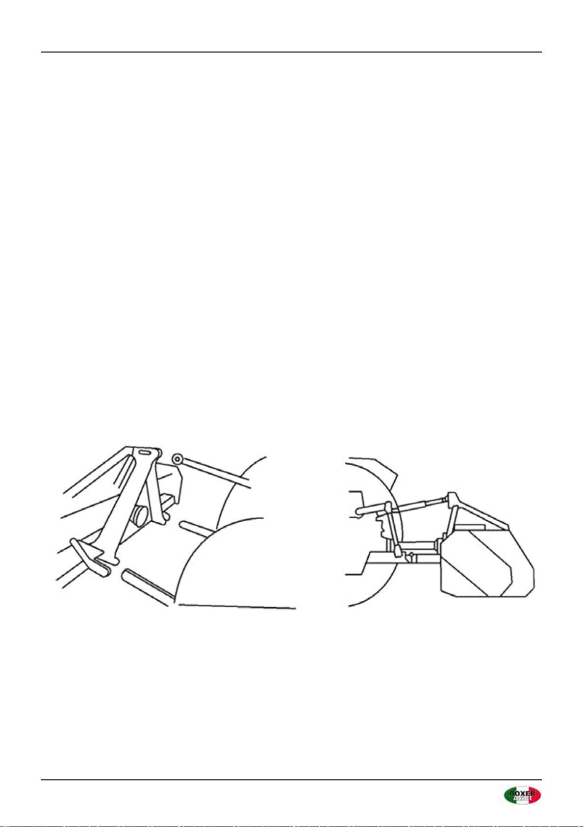
Before attaching the equipment to the tractor, set both on a flat and smooth ground and make sure that nobody is
standing between them.
Move slowly the tractor towards the flail mower by aligning the tractor hydraulic lift arms to the two mower hitches'
lateral brackets; stop engine and set parking brake.
Connect first the lower arms by removing the release pins of the brackets placed on the plates, inserting the lift arms
into the arms center and fastening them with the relevant release pins, which had been removed.
Connect, then, the tractor top link to the third upper point by removing the pin located between the plates, inserting
the top link itself and locking it with the pin.
Page 11/26
December 2020FRONT AND REAR MULCHER | User manual
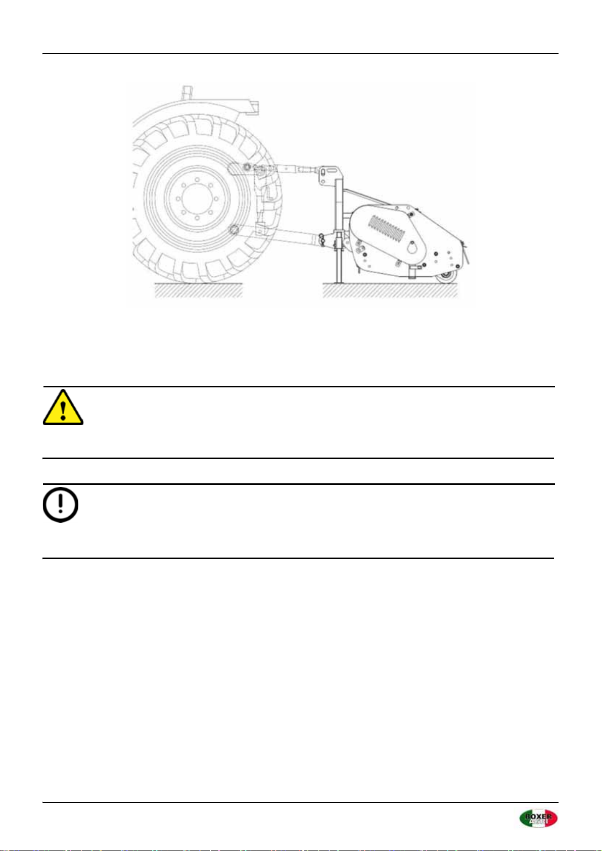
SET UP
Adjust the third point so that the upper part of the frame is parallel to the ground. Lock all connection parts with
the special sway chains or tie rods.
It is always good to make sure that the central gearbox axis is parallel to the ground thus reducing the stresses on
the power takeoff and extending the working life of the equipment.
CAUTION
Pay attention to the tractor's front wheels grip when the equipment is set up and lifted; if the wheels appear to be
too lightened, ballast the tractor front tires or add front weights.
IMPORTANT
After executing the above mentioned activities it is always good to check that all bolts and nuts of your shredder are
tightened strongly (refer to the torque specifications in this manual).
4.2 Driveline attachment
Before assembling the PTO shaft, check out that its RPM and direction of rotation match those of the tractor.
Moreover, read carefully the instruction manuals of the PTO shaft and the tractor manufacturers. Before starting
work, make sure all safety shields are in place. Check in particular that the safety guards cover the PTO shaft
throughout its extension. When attaching the mower input driveline to the tractor PTO, be sure that the connecting
yoke spring activated locking collar slides freely and the locking balls are seated securely in the groove on the tractor
PTO shaft. A driveline not attached correctly to the tractor PTO shaft could come loose and result in personal injury
and damage to the implement.

Page 12/26
FRONT AND REAR MULCHER | User manual December 2020
CAUTION
Make sure the driveline will not bottom out (at its most compressed position there must be at least a 3/4" clearance
between each profile end and opposite profile universal joint) or become disengaged (at its farthest extended
position a minimum profile engagement of 1/3 of the length must be maintained).
Check out that the cardan shaft minimum and maximum length are
the ones required by the machine-tractor coupling. Should problems
arise, contact a skilled repair shop or the driveshaft retailer. After
installation, secure safety guards both to the tractor and the machine
using the special chains and make sure that they pivot freely. If the
PTO shaft is equipped with other safety devices, such as a pair limiter
or freewheels, be sure to install them on the machine side. As for the
PTO use and maintenance refer to the relevant booklet.
4.3 Working height adjustment
The machine's working height is determined by the position of the
rear roller. Lifting the roller the cutters get close to the soil, whereas lowering it the cutters get far from it. After a
modification of the working height be sure that the cutters skim the ground; a direct contact with it would cause
their wear and this could affect the cutting rotor balance and may cause objects to be thrown out from under the
mower deck.
FLAIL MOWER ADJUSTMENT
1. On a flat piece of ground, attach the Flail Mower to the tractor
using the three point linkage.
2. Use a solid adjustable top link.
3. Lower the three point linkage to its lowest position
4. With the roller at the rear in contact with the ground, adjust the
length of the top link so that the lower edge at the side of the flail
mower is parallel with the ground.
5. Rotate the blade drum by hand so that a row of blades hang
vertically towards the ground.
6. Measure the clearance between the bottom of the extended
blades and the ground.
- Minimum 50mm.
- Note: In rough or lumpy paddocks the clearance needs to be increased to ensure that the blades don’t
impact the ground in operation.
7. Adjust the roller height to increase or decrease the blade clearance as required.
8. Go through steps 4 to 7 until the required clearance is achieved.
When the Flail Mower has been set up with the required tolerances, operate the Flail Mower with tractor in low
range and the PTO delivering 1000 RPM.

Page 13/26
December 2020FRONT AND REAR MULCHER | User manual
4.4 Drive belt adjustment
1. Loosen the Screw A and B that locks the support shaft and loosen the counter
nut C. Loosen the screws that lock the gear box on the mounting plate D.
2. Adjust the drive belt tension. The correct belt tension is achieved when the
belt can be deflected by the belt thickness about 10mm at the center point
between the pulleys.
3. Align the gearbox so the drive shaft is parallel with the body.
4. Use a straight edge to make sure the belt pulleys are in line and running true.
If misaligned, call your dealer or service agent for technical support.
5. Fit the safety covers and tighten the mounting bolts before operation.
Approx 10mm deflection Align with a straight edge

Page 14/26
FRONT AND REAR MULCHER | User manual December 2020
5. TRANSPORT
5.1 Working speed
The working speed depends on quality, diameter and height of the material to be cut; anyway, for efficient mower
performance it must be between 2 and 5 MPH. The power takeoff speed must be 1000 RPM maximum. Operate the
mower at its full rated PTO speed to maintain blade speed for a clean cut.
CAUTION
Do not exceed the rated PTO speed for the implement. Excessive PTO speeds can cause driveline or blade failures
resulting in serious injury or death.
5.2 Road transport
Extreme caution should be used when transporting the tractor and implement on public roadways. The tractor must
be equipped with all required safety warning features including a SMV emblem and flashing warning lights which
are clearly visible from the rear of the unit. Make sure you are in compliance with all local regulations regarding
transporting equipment on public roads and highways. Do not exceed 20 MPH (32 kph). Reduce speed on rough
roads and surfaces. Always use hazard flashers on the tractor when transporting unless prohibited by law.

Page 15/26
December 2020FRONT AND REAR MULCHER | User manual
6. STORAGE
If your shredder will not be used for a long period of time, respect the following suggestions:
1. Wash the machine thoroughly and dry it.
2. Lubricate all bearings with enough grease to eliminate any cavities where water condensation may occur and
cause damage. Refer to 7. "MAINTENANCE" for location of all grease fittings. Be sure the vent on top of the
gearbox is open.
3. Loosen the set nut and spindle jack to relieve drive belt tension (NOTE: Before next season's use, be sure to
adjust the drive belt tension.)
4. Coat all exposed surfaces inside the mower with oil or grease to prevent rusting and pitting during storage.
5. Protect the whole machine with a tarpaulin and put it in a dry place.
6.1 Pre-season check
1. Check the oil level in the gearbox and lubricate all bearings. See "Lubrication".
2. Adjust drive belt tension. See "Belt Drive".
3. Check out all equipment and replace damaged or worn parts.
4. Tighten all bolts and nuts (See "Torque Specifications").
5. Inspect for missing and/or broken blades/knives. Replace as necessary. See "Knife Replacement".
6. Be sure that the safety guards are in place and secure.
7. Run the Flail Mower at a low RPM checking to make sure that all driveline parts are moving freely.

Page 16/26
FRONT AND REAR MULCHER | User manual December 2020
7. MAINTENANCE
Maintenance is a fundamental operation to extend life and performances of any agricultural vehicle; taking care of
the machine grants you not only a good work execution, but also a longer life of the whole equipment and a greater
safety on the workplace.
The operating times indicated in this manual have just an informative character and are referred to normal
conditions of use; they can thus undergo variations according to the type of service.
CAUTION
• Before injecting lubricating grease into the zerks, clean them accurately to prevent mud, dust, or other foreign
matters from mixing up with grease, thus diminishing the lubrication effect.
• When adding or changing oil, it is better to use the same oil type, in order to avoid mixing oils with different
features.
• Before executing maintenance activities on the machine, stop engine, disengage power takeoff, set parking
brake and place the equipment on the ground in horizontal position.
• After the first working hours, check that all bolts and nuts are tightened; remember also to check often all the
machine safety guards.
FIRST CHECK
• Check the correct tension of the driving belt
• Check that all bolts and nuts are tightened
• After the first 50 hours of work, change oil in the gearbox
EVERY 8 HOURS OF WORK
• Rotate teardrop shaped plate B and grease the shaft support (driveline side) through the lubricating nipple A
(picture 1).
• Grease the shaft support (external side) through the lubricating zerk A (picture 2).
• Grease the shaft support (driveline) and the belt tensioner idler pin through the lubricating zerks A and B
(picture 3).
• Grease the stabilizing roller through the lubricating zerk A (picture 4)
EVERY 50 HOURS OF WORK
• Check the correct tension of the driving belt
• Check that all bolts and nuts are tightened
• Check the cutters/hammers for wear
• Check the overgear unit oil level through plug A (picture 5)
EVERY 500 HOURS OF WORK
• Check that all bolts and nuts are tightened
• Change oil in the overgear unit

Page 17/26
December 2020FRONT AND REAR MULCHER | User manual
EVERY 1000 HOURS OF WORK
Replace the driving belt.
GEAR BOX MAINTENANCE
The oil should be drained out and replaced after the first 50 hours of operation. Then the oil should be changed
every 250 hours, or at least once a year.
Drain oil from the gearbox thoroughly. Check and clean it. Fill with new gear oil up to the dedicated oil level.
The draining procedure is as follows: remove the draining bolt under the gear box, so that the oil drains off. After
the oil is drained out, put the plug back and fill with gear oil up to the dedicated oil level.
PTO SHAFT MAINTENANCE
The PTO shaft is designed to telescope to allow for dimensional changes as the machine goes through its operating
range. A tubular guard encloses the driving components and is designed to turn relative to the driving components.
The shaft should telescope easily and the guard turn freely on the shaft at all times. Annual disassembly, cleaning
and lubrication is recommended to insure that all components function as intended. To maintain the shaft, follow
this procedure:
1. Remove the shaft from the machine.
2. Pull shaft apart.
3. Use a screwdriver to pry the tabs out of the sleeves on each end.
4. Pull the shaft out of the plastic tubular guard.
5. Use a solvent to clean the male and female portions of the telescoping ends.
6. Apply a light coat of grease to each end.
7. Clean the grooves on each end where the tabs are located. Clean each tab also.
8. Apply a light coat of grease to each groove.
9. Insert the shaft into its respective guard and align the slots with the groove.
10. Insert the tabs through the slots and seat in the groove.
11. Check that each guard turns freely on the shaft.
12. Assemble the shaft.
13. Check that the shaft telescopes easily.
14. Replace any components that are damaged or worn.
15. Install the shaft on the machine.
8hrs/Daily 50hrs/Weekly Annually
Lubricate PTO Shaft x x x
Lubricate caster wheels x x x
Lubricate blade spindle x x x
Check gear box oil level x x
Clean machine x
Lubricate and clean PTO shaft cover x
Page 18/26
FRONT AND REAR MULCHER | User manual December 2020
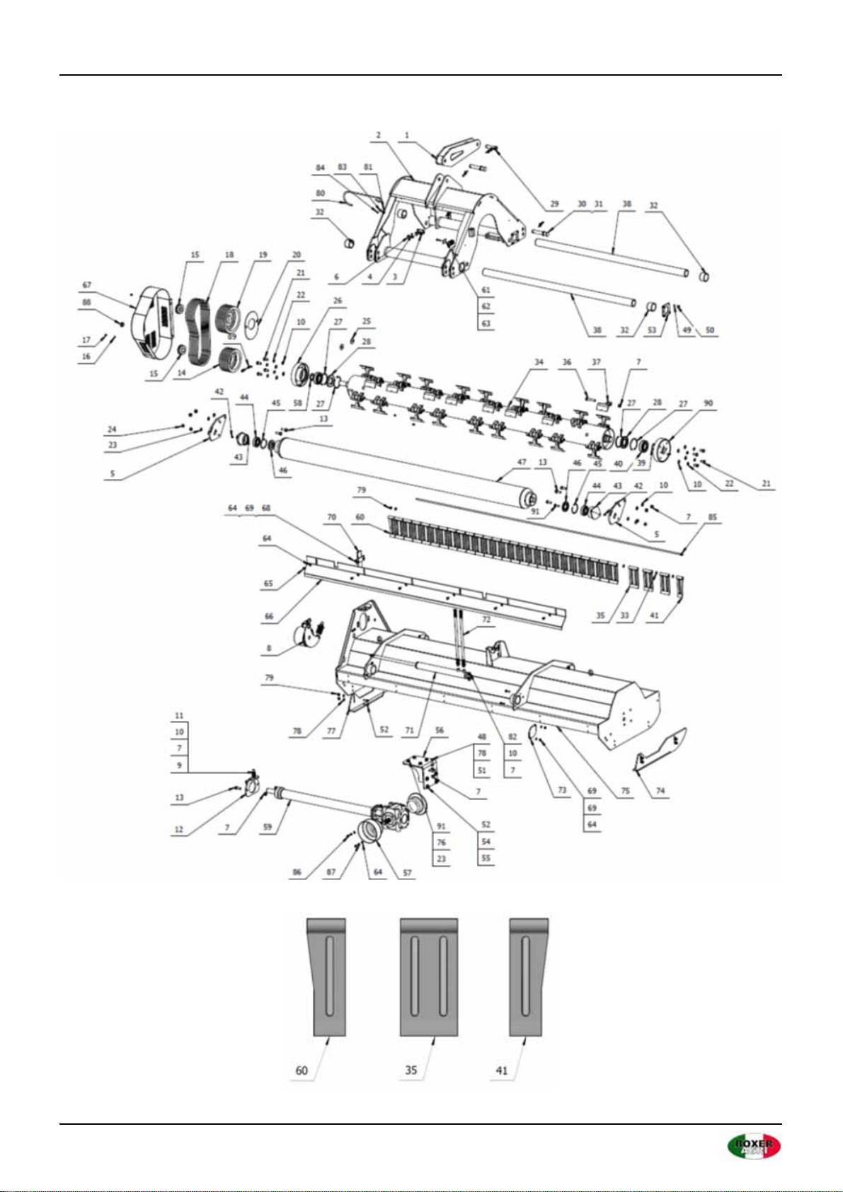
8. PARTS LISTS

Page 19/26
December 2020FRONT AND REAR MULCHER | User manual
DUO 250/280/300 plus
Item ERP No. Parts No. Name QTY
1 810110035 EFAG300-027-00 Connecting plate 1
2 810110031 EFAG300-020-00 Suspension frame 1
3 709510107 EFAG300-000-02 Pedestal 1
4 506030035 GB93-8 Spring washer 2
5 709510111 EFAG300-000-06 Roller hanging board 2
6 501011098 GB5783-M8x16 Full screw bolt 2
7 503010313 GB6184-M16 Metal locking nut 44
8 810110023 EFAG300-023-00 Tensioning wheel 1
9 501011166 GB5783-M16x90 Full screw bolt 1
10 506010059 GB97.1-16 Flat gasket 18
11 503010102 GB6172.1-M16 Thin nut 2
12 709510113 EFAG300-000-08 Adjusting plate 1
13 501011159 GB5783-M16x45 Full screw bolt 6
14 709510115 EFAG300-000-10 Small belt pulley 1
15 515010003 REACH15-40X80 Lock cap 2
16 506010055 GB97.1-8 Flat gasket 3
17 503010309 GB6184-M8 Metal lock nut 3
18 514030016 XPB1540 Belt 5
19 709510116 EFAG300-000-11 Big belt pulley 1
20 709510117 EFAG300-000-12 Belt pulley board 1
21 501011156 GB5783-M16x30 Full screw bolt 8
22 506030039 GB93-16 Spring washer 8
23 506010058 GB97.1-14 Flat gasket 8
24 503010312 GB6184-M14 Metal lock nut 4
25 506010039 GB96.1-16 Extra large flat gasket 2
26 709510034 EFAG300-009-00 Right bearing pedestal 1
27 506060203 GB893.1-110 Check ring 4
28 510020678 GB13871-FB-60X110X12 FB oil seal 2
29 805760001 1G-180.00.019 Upper suspension pin 1
30 706790181 EFAG140.014A-1 (AG200/220/250) Below suspension pin 3
31 700080010 200.56.011 Lockpin assembly 3
32 511050257 SF-2-70X75X50 Self-lubricating bearing 4
33 506010057 GB97.1-12 Flat gasket 20
34-1 809510011 EFAG300-014-00 Blade shaft (300) 1
34-2 806710011 EFAG280-014-00 Blade shaft (280) 1
34-3 809800011 EFAG250-014-00 Blade shaft (250) 1
35 710110039 EFAG300-000-14A Board 28
36 501010783 GB5782-M16x90 Half thread bolt 34

Page 20/26
FRONT AND REAR MULCHER | User manual December 2020
37 709510114 EFAG300-000-09 Hammer 34
38 710110038 EFAG300-000-01a Guide rail shaft 2
39 506060325 GB894.1-50 Check ring 1
40 511011084 GB288-21310-C Self aligning roller bearing 2
41 710110040 EFAG300-000-15A-L Board 1
42 509010009 GB1152-M10X1 Oil cup 3
43 809510009 EFAG300-012-00 Roller bearing pedestal 2
44 511024244 GB281-1308 Self aligning roller bearing 2
45 506060195 GB893.1-90 Check ring 2
46 510020416 CFW-50X90X10 FB oil seal 2
47-1 809510006 EFAG300-008-00 Roller (300) 1
47-2 806710009 EFAG280-008-00 Roller (280) 1
47-3 809800009 EFAG250-008-00 Roller (250) 1
48 501011136 GB5783-M12x90 Full screw bolt 1
49 506030035 GB93-8 Spring washer 16
50 501011098 GB5783-M8x16 Full screw bolt 16
51 503010100 GB6172.1-M12 Thin nut 2
52 501011128 GB5783-M12x40 Full screw bolt 12
53 710110042 EFAG300-000-20 Board 4
54 506030037 GB93-12 Spring washer 4
55 506010037 GB96.1-12 Extra large flat gasket 4
56 810110029 EFAG300-013-00a Gear box adjustment pedestal 1
57 703400202 FM120.00.199C PTO cover 2
58 510020677 GB13871-FB-50X62X5 FB oil seal 1
59-1 809510133 EFAG300-100-00 Transmission box (300) 1
59-2 806710018 EFAG280-100-00 Transmission box (280) 1
59-3 809800018 EFAG250-100-00 Transmission box (250) 1
60 710110041 EFAG300-000-15A-R Board 1
61 704660020 QHTT-G3 Cover plate 1
62 704660021 QHTTPG-320 Duplex pipe clamp 1
63 501011103 GB5783-M8x40 Full screw bolt 1
64 506010056 GB97.1-10 Flat gasket 20
65 501011111 GB5783-M10x20 Full screw bolt 6
66-1 709510112 EFAG300-000-07 Roller hanging board (300) 1
66-2 706710017 EFAG280-000-07 Roller hanging board (280) 1
66-3 709800017 EFAG250-000-07 Roller hanging board (250) 1
67 810110024 EFAG300-026-00 Pulley cover 1
68 501011114 GB5783-M10x35 Full screw bolt 10
69 503010310 GB6184-M10 Metal lock thin nut 10
DUO 250/280/300 plus
Item ERP No. Parts No. Name QTY
Table of contents
Other BOXER AGRI Lawn Mower manuals


