BOXER BM 100 User manual

Identification Data
Description
1. Technical Specifications......................1
2. Location of Parts.................................2
3. How to Ride Motorcycle.....................9
4. Safe Riding Tips..................................10
5. Daily Safety Checks............................ 11
6. Running In Instruction......................... 12
7. Periodic Maintenance Information............13
8. Periodic Maintenance & Lubrication........ 15
9. Periodic Part Replacement Schedule...... 17
10. Pre Delivery Inspection............................ 18
11. Applicable to Periodic Services.............. 19
12. Non-use Maintenance.............................. 20
Notice: The description and illustration in this booklet are not to be taken as binding on the
manufacturers. The essential features of the type described and illustrated herein remaining
unaltered. Bajaj Auto Limited reserves the right to carry out at any moment without being
obliged to bring this booklet upto-date. Modifications on the vehicle, parts or accessories
as may be convenient and necessary.
Safety and Warning information :
Warning : This indicates that a potential hazard or injury to you or other persons & to the
vehicle can happen if advice provided is not followed
Caution : This indicates that a potential hazard that could result in vehicle damage. Follow
the Advice provided with the caution.

2
1
Engine : 4 stroke, Single cyl.
Air cooled, SI Engine.
Bore x Stroke : 53.0 mm x 45.0 mm
Engine Displacement : 99.27 cc
Compression Ratio : 9.5 : 1
Idling Speed : 1300 + 100 rpm
Max. Net Power : 6.03kW (8.2Ps) at 7500
rpm
Max. Net Torque : 8.05 Nm at 4500 rpm
Ignition System : Digital CDI with twin
map ignition
Spark Plug : Mico UR3AC,
Champion PRZ9HC
Spark Plug Gap : 0.6 to 0.7 mm
Lubrication : Wet sump, Forced.
Transmission : 4 speed constant mesh.
Brake Front / Rear : Mech. expanding shoe.
Fuel Tank Capacity :
Full : 9.3 litres
Reserve : 2.2 litres
Usable Reserve : 1.2 litres
Tyre Size :
Front : 2.75 x 17
Rear : 3.00 x 17
Tyre Pressure :
Front : 1.75kg / cm2 (24.5 PSI)
Rear (solo) : 2 kg / cm2 (28 PSI)
Rear (pillion) : 2.50 kg / cm2 (36 PSI)
Dimensions :
Length : 1970 mm
Width : 770 mm
Height : 1065 mm
Wheel base : 1235 mm
Min. Turning radius : 1900 mm
Ground clearance : 150 mm (Min.)
Electrical System : 12 Volts AC + DC
Head Lamp : 35/35 W
Position Pilot Lamp : 3W
Stop Lamp/Tail Lamp : 21 W / 5 W
Turn Signal Lamp : 10 W
Neutral Indicator Lamp : 3 W
Hi Beam Indicator Lamp : 3 W
Turn Pilot Indicator Lamp : 3 W
Speedometer Lamp : 3 W (2 Nos.)
Horn : 12 V DC
Battery : 12 V-2.5 Ah
Vehicle Kerb Weight : 109 kg.
Gross Vehicle Weight : 239 kg.
Max. Speed : 90 km/hr.
(single rider 68 kg)
0
Climbing ability : 25% (14 ) max.
Note : All dimensions are under UNLADEN
condition. Above information is subject to
change.
Technical Specifications Location of Parts
Clutch Lever
Fuel Tank Rear Shock
Absorber
Grab
Handle
Pillion
Foot Rest
Side Stand
Center
Stand
Gear
Change Lever
Front Fork

4
3
Location of Parts
1. Mirror - LH/RH
2. Control Switch LH
3. Speedo Console
4. Control Switch RH
5. Throttle Grip
6. Indicators LH/RH
7. Fuel Tank Cap
12341
6 6
7
5
The Frame and Engine serial numbers are
used to register the motorcycle. They are
the unique alpha-numeric codes to identify
your particular vehicle from others of the
same model and type.
Engine Number
Frame Number
Location of Parts
1. Turn Signal Indicator (LH & RH) : When
turn signal switch is turned to Left or Right,
Turn pilot indicator will flash with engine
running.
2. Speedometer : The Speedometer pointer
shows the speed of vehicle.
3. Odometer : The Odometer shows the total
distance that the vehicle has accumulated.
4. Hi beam Indicator : When Headlight is
‘ON’ and Hi beam is selected with engine
running, Hi beam indicator will be lit.
N
5. Neutral Indicator :
When the transmission is in Neutral and
Ignition switch ‘ON’, with engine running
the Neutral indicator is lit.
6. Ignition Switch : Key operated switch
for Ignition ‘ON’/‘OFF’.
OFF : Ignition OFF.
ON : Ignition ON.
Ignition ON & OFF :
OFF ON
6
5
Location of Parts
Steering Lock ON & OFF :
To Lock the Steering : To lock the steering,
turn the handle bar to the left. Turn the key to
“LOCK” position and remove the key.
To Lock the Steering : To lock the steering,
insert the key in steering lock & turn it
anticlockwise to “ON”.
To Unlock the Steering : To unlock the
steering, insert the key in steering lock & turn
it clockwise to “OFF”.
Key : A common key is used for Steering
lock, Ignition lock, Fuel tank cap and Side
cover lock.
Fuel Tank Cap
•To open the fuel tank cap, insert the key
in the lock and turn it clockwise and lift
fuel tank cap.
•‘Fuel Tank Cap’ is locked when pushed
back into the place.
Fuel Tap
Fuel tap lever has following positions.
ON : When fuel level is above Reserve
position.
RES : When fuel level is below Reserve
position.
OFF : When fuel supply is to be cut off.
Fuel Tank
Cap Fuel Tap
OFF
ON
RES
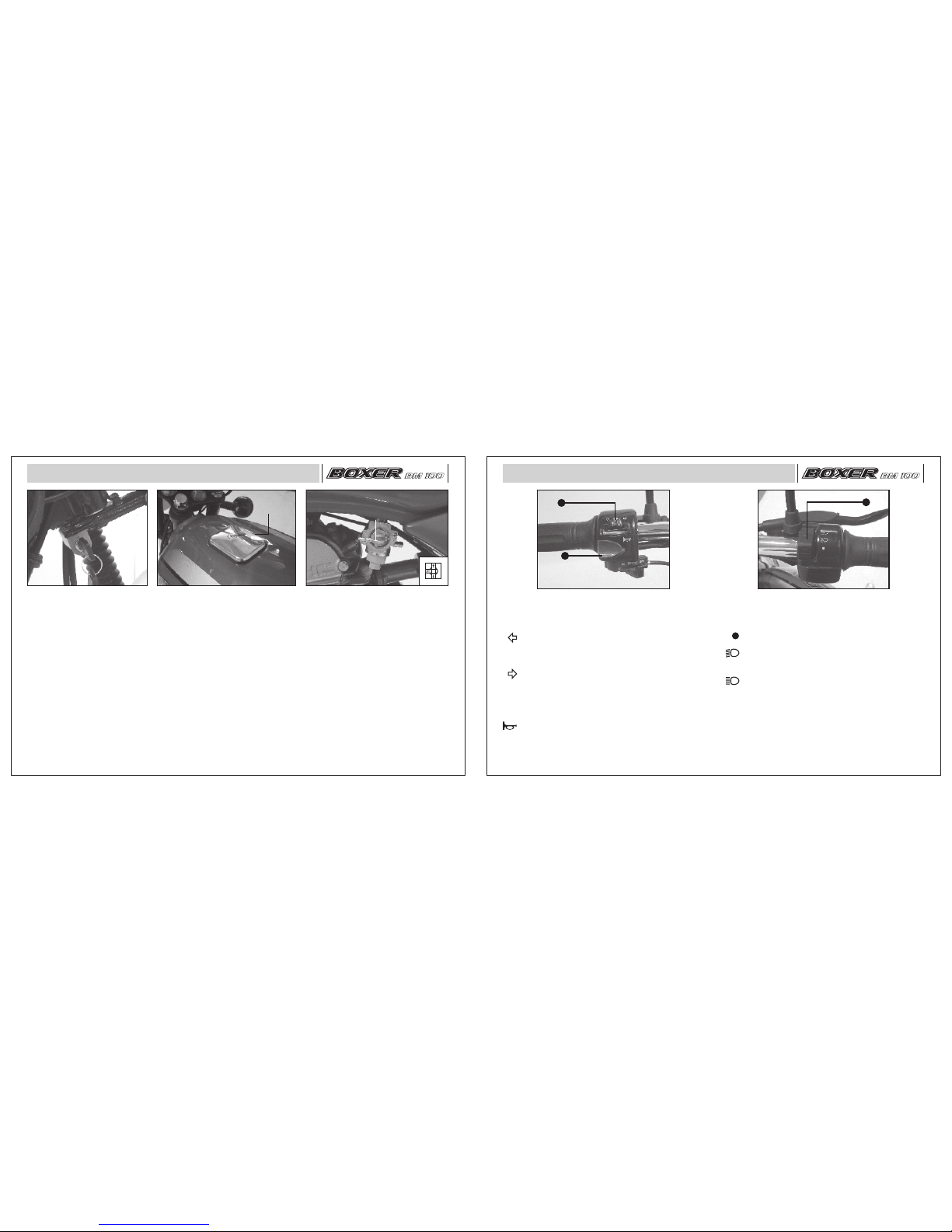
Location of Parts
A. Turn Signal Switch :
: When the turn signal switch is turned to
Left the Left side Front and Rear turn
signal flash ‘ON’ and ‘OFF’.
: When the turn signal switch is turned to
Right the Right side Front and Rear
turn signal flash ‘ON’ and ‘OFF’.
B. Horn Button :
: Press horn button for sounding horn.
A. Head Light Switch : It has 3 positions.
:All lamps 'OFF'.
:With engine running, Low beam, Tail
lamp and Meter lamps ‘ON’.
:With engine running, High beam, Tail
lamp and Meter lamps ‘ON’.
A
Right Handle Bar Switches
B
A
Left Handle Bar Switches

87
Location of Parts
SIDE
COVER LH
A
B
C
SIDE
COVER RH
D
B
A
Removal Of Side Cover LH and RH
• Insert the key into cover lock (C) & turn
the key clockwise & pull ‘Side cover’ LH
out from bottom.
• Pull ‘Side cover’ from (A) to release Lug
provided on ‘Side cover’ from hole
provided on ‘Frame’.
• Slide the ‘Side Cover’ forward (towards the
engine) from location (B) to release slot
provided on front side of ‘Side cover’ from
bracket with rubber cap provided on ‘Fuel
Tank’. Take out ‘Side cover’.
• Similarly ‘Side cover’ RH can be removed
after removing screw (D).
Caution : Remove cover as described
above, otherwise the lugs may break.
Fitment Of Side Cover LH and RH
• Match slot (B) provided on front side of
‘Side Cover’ with bracket provided on
‘Fuel Tank’ and slide ‘Side cover’
backward (towards Tail lamp).
• Match Lug (A) provided on rear side of
‘Side cover’ with hole provided on
‘Frame’ and press ‘Side cover’ inside.
• Match the lock plate of ‘Side cover’
properly with bracket on ‘Chassis’ and
Lock. (For ‘Side cover’ LH).
• For ‘Side cov e r’ RH adopt same
procedure and fit the screw (D) properly.
Caution : Fit cover as described above to
ensure proper fitment.
Location of Parts
FRONT
BRAKE
ADJUSTER
Front Brake Adjustment
For safe riding, the brakes must always be
maintained in perfect condition. Brake is
properly adjusted if
• The wheel rotates freely when the
control lever is in the resting position.
• The braking action starts after Front
brake lever is pressed by 2-3 mm.
These conditions are obtained by adjusting
the cables by means of adjuster shown in
the figure and minor play adjustments can
be done by adjuster provided near front
brake lever.
Rear Brake
Rear brake is properly adjusted if
• The wheel rotates freely when the brake
pedal is in the resting position.
• The braking action starts after Brake
pedal is pressed by 20-30 mm.
These conditions are obtained by adjusting
the cables by means of adjuster shown in
the figure.
Warning :
Brakes are items of personal safety and
hence must be maintained in perfect
condition.
Adjustment
REAR
BRAKE
ADJUSTER
This manual suits for next models
1
Table of contents
Other BOXER Motorcycle manuals

Popular Motorcycle manuals by other brands

MV Agusta
MV Agusta Brutale 675 Workshop manual

APRILIA
APRILIA RSV MILLE - PART 1 1999 User manual content

Royal Enfield
Royal Enfield Himalayan 2018 owner's manual

SSR Motorsports
SSR Motorsports Lazer5 owner's manual

MOTO GUZZI
MOTO GUZZI 2005 Griso 1100 Use and maintenance book

KTM
KTM 85 SX 19/16 owner's manual


