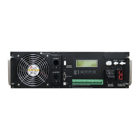
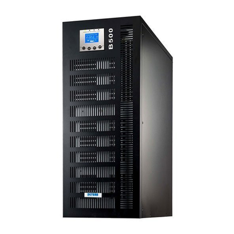
BPE PB Series User manual

User Manual
1
PB Series UPS

2
CONTENTS
1. System Introduction ............................................................ 3
2. Safety Instructions.............................................................. 4
3. Front Panel Indications ....................................................... 4
4. Installation & Operation..................................................... 5
5. Startup process of UPS................................................... 6
6. rouble Shooting................................................................. 7
7. Warranty Certificate........................................................... 8

3
1. SYSTEM INTRODUCTION
BPE PB Series UPS is an advanced true On-Line Uninterrupted Power System
which produces reliable and pure sine wave power to user's equipment,
ranging from computers, sensitive medical instruments, and
telecommunication systems to industrial equipment. he On-Line design
enables the system to adjust & filter power fluctuations continuously &
automatically under power normal condition. During power failure, it can
provide immediate back up power from the external batteries without any
interruption. Once the power is restored the system shall again work on mains
& will charge the batteries.
Block Diagram
IGBT & PWM TECHNOLOGY
BPE make PB series UPS used the latest generation IGB (Insulated Gate Bipolar
ransistor), is used in the inverter part of the UPS. With the Pulse width
Modulation technique, maximum operational efficiency is obtained and thus
even the non-linear loads are fed with precise sinusoidal signal.

4
2. SAFETY INSTRUCTION
•his manual contains important safety instructions which must be
strictly followed during installation & maintenance.
•he UPS contains voltages which are potentially hazardous. Please
contact our offices or qualified personnel for any services required.
•
The UPS is compatible to external strorage energy source( battery).
So proper verification of the batteries with terminal is required
before connecting to the UPS.
•Ground wire must be connected at the input at the time of installation.
•UPS should be connected with single phase input 230V, 3 wire
phase, neutral and earth and respective points marks L N E.
•Batteries must be replaced or maintained by qualified personnel.
•Replacement of batteries must be subject to quantity and types of
original specifications.
•o avoid explosion, keep fire or heating resources away from battery or
battery pack.
•Do not disassemble or damage the batteries. he electrolytic of
battery is poisonous and harmful especially to eyes and skin.
•he batteries contain high voltage and current with great risk.
•Do not short circuit the battery terminals.
3 A. Front Panel Diagram

5
3 B. Rear Panel Diagram
4. INSTALLATION & OPERATION
Unpacking & Inspection -
Examine the packing carton. Notify the carrier immediately, if damage is present.
Retain the package for future use.
UPS Installation -
Connect the I n p ut power to a MCB of recommended Capacity of distribution
board. Charge the batteries for 8 hours before use so that all batteries attend
similar voltage level. he UPS will recharge the batteries automatically whenever
its power card is plugged into a wall outlet. You may use the UPS
immediately without recharging but the backup time may be less than the rating.
Connect the output load to the UPS. It is mandatory to connect ground point to
avoid any malfunctioning of UPS.
Operational Instructions -
Ensure that the installation procedures and metering, controls, indications as
specified, are followed and the battery of rated voltage is connected to the system.
3/1
1/1

6
STARTUP PROCESS OF THE UPS
i. Please connect the mains power and the Battery wire at the terminal
block of UPS properly.
ii. Make the Input Power ON and check the voltages at the UPS terminal
Block and also check the battery voltage.
iii. Once all voltage seen normal, close the Input mains breaker. Press Start
Switch “INVER ER ON LED” will glow and output AC voltage can be seen
on the meter. After about 10 sec, “LOAD ON INVER ER LED” will glow.
Check the output voltage as required on meter. Verify the battery
charger voltage at terminal and then close the battery MCB, after
confirming the voltage.
iv. Connect the load at output of the system and ensure its satisfactory
working.
v. he Inverter may trip in following conditions.
(a) Overload
(b) DC Under/ Over Voltage
(c) Output (AC) Over Voltage.
(d) DC bus high
However, if so happens the respective LED will indicate the cause of tripping. After
removal of the respective cause, inverter can be started again by pressing start
switch.

7
IMPORTANT
Before Switching ON Or Switching OFF the Inverter, Switch off all the loads at the ouput
.
TROUBLE SHOOTING CHART
PROBLEM
PROBABLE CAUSE
REMEDY
DC Fuse Fail A.Skin effect due to prolong use
B.Short Circuit on Excessive overload
on Inverter
A.Replace Fuse
B.Check the inverter o/p for
excessive over loading. Reduce the
load to the limit and check the
inverter.
DC under voltage comes immediately
after the inverter is switch ON ( No
load) and Inverter rips
A.DC input cable is less than the rated
capacity
B.Loose contact in output Line
A.Replace the cable, use the cable
of proper rating
B. ighten all the connections
DC under voltage indication comes
on when working on battery and
Inverter rips.
A.Battery is Discharged.
B.Battery cable is of lesser capacity
than rated.
A.Keep the battery in charged
Condition
B.Replace the cable with a rated
ampere cable.
Inverter Not getting ON A.Break in the DC supply either due to
blown fuse or disconnected wire.
B.Control Card not receiving the DC
supply or same wire got de-soldered.
C.Control Card Defective
A.Replace Fuse or Check wiring as
necessary.
B.Check Inverter fuse and replace if
found faulty or check control wiring
as may be required.
C. Replace control card
Over load LED Flashing with no
output
A.Feed back fail
B.Short Circuit
A.Check feedback transformer or
break in wiring of transformer.
B.Remove the load and see the
short circuit removed, there may
be load short circuited.
Inverter trips before loaded fully. Over load trip setting not proper Set Overload tripping by means of
adjusting the Potentiometer of
inverter card.
Check Power requirement of the
load. Switch on the load one by
one after the output voltage
reaches 230V

8
WARRANTY CARD
Sl. No
Purchase Date
Dealer Information:
Name.......
Address.......
....................
FOR SERVICE
Best Power Equipments (I) Pvt. Ltd.
G-215, Sector-63, Noida-201307, Uttar Pradesh, India
Service oll Free Call: 1800 1031 247 Mob-+91-9310995859
Table of contents
Other BPE UPS manuals
Popular UPS manuals by other brands
Ever Power Systems
Ever Power Systems POWERLINE RT PLUS 1000 instruction manual
GMP
GMP GM 110 PRO user manual
PowerWalker
PowerWalker VI 1200 RLE user manual
Bicker Elektronik
Bicker Elektronik UPSI-2406DP user manual

Eaton
Eaton Power Xpert Plus 1 Installation and operation manual

Huawei
Huawei UPS5000-S Series user manual
