2
SELECTEUR D’ENTREE SI/200
Cet appareil permet de sélectionner
2 postes extérieurs et il est prédispo-
sé pour la réalisation des typologies
d’installation suivantes:
•Installations pour pavillon ou pour
immeuble avec plusieurs entrées en
utilisant un nombre de sélecteurs
équivalent à celui des postes exté-
rieurs moins un.
•Installations résidentielles en utili-
sant l’appareil comme sélecteur de
bloc d’habitation.
Caractéristiques
fonctionnelles du sélecteur
•Protection de liaison éventuelles en
cours et gestion de la signalisation
d’occupé, soit si utilisé comme sélec-
teur pour plusieurs postes extérieurs,
soit si utilisé comme sélecteur de
bloc dans des installations résiden-
tielles.
La protection est ainsi désactivée:
-2minutes environ après l’appel;
-lors de la remise en place du
récepteur (cavalier SW1 inséré);
-de manière permanente (cavalier
SW2 inséré).
•Le sélecteur est muni d’un amplifi-
cateur qui regénère le signal d’appel.
•Possibilité de relier à une même
appel jusqu’à 3 postes intérieurs.
•Possibilité de reconnaître le poste
extérieur d’où provient l’appel, grâce
à une note différenciée pour 2
entrées.
Pour obtenir cette fonction relier la
borne 8A du sélecteur SI/200 à la
borne 8A de l’alimentation employé
(A/200, A/241, etc.)(fig. 3).
En ce cas il n’est pas possible reali-
ser la connexion pour un eventuel
appel de la porte-palière.
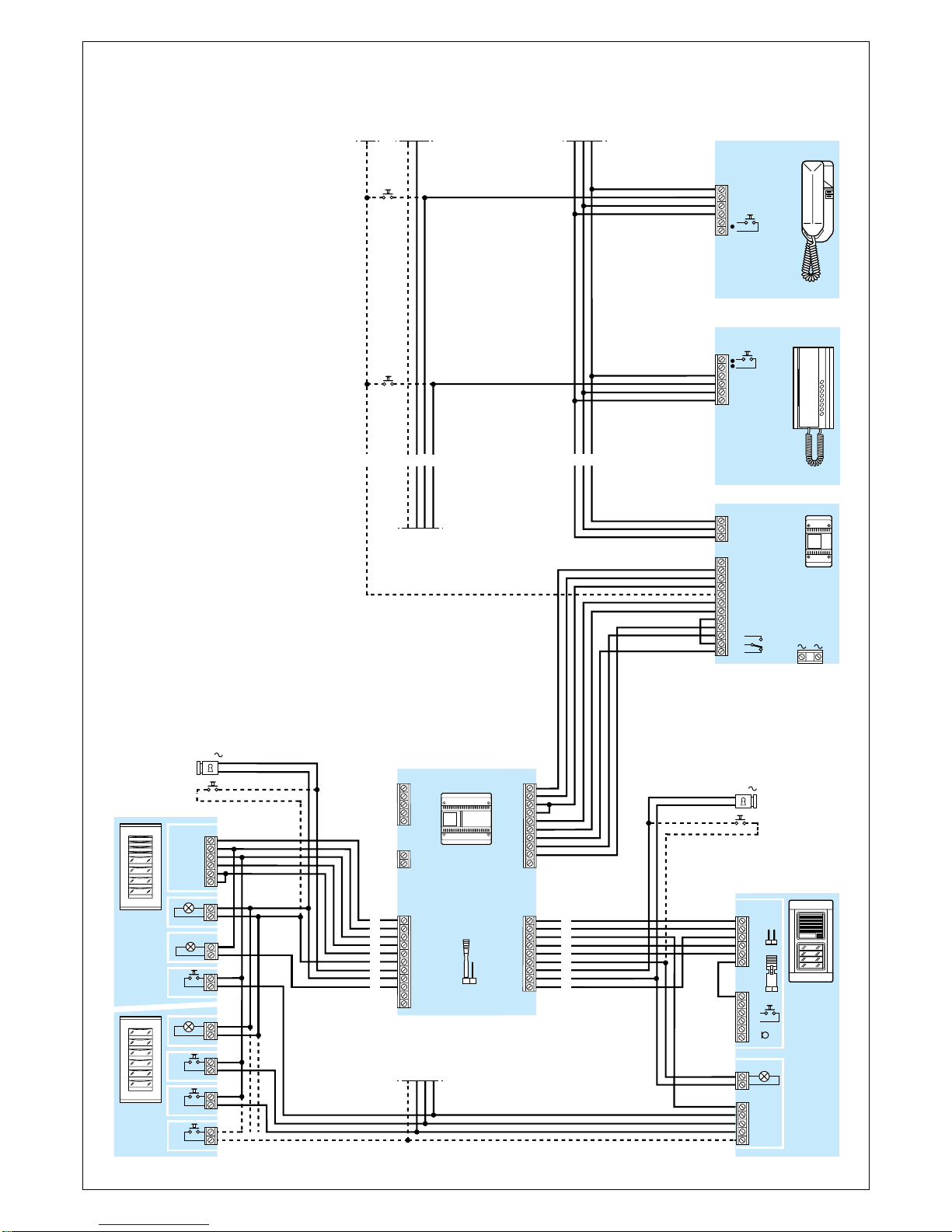
Fonction des bornes (fig. 1)
Bornier B (à l’alimentation ou au
sélecteur précédent)
5–11V alimentation
21 +poste extérieur
8commun appel 1
8A commun appel 2
11 audio au poste intérieur
12 audio au poste extérieur
23 entrée 14Vca
13 gâche électrique
16 0Vca
24 entrée signalisation d’occupé
Bornier E (au poste extérieur n. 1)
5–11V alimentation
21 +poste extérieur
8commun appel
11 audio au poste intérieur
12 audio au poste extérieur
23 entrée 14Vca
13 gâche électrique
16 0Vca
24 sortie signalisation d’occupé
RS reset (1)
Ehabilitation audio
(1)Fonctions prévues pour installa-
tions mixtes (combinés et moniteurs).
Bornier F (au poste extérieur n. 2 ou
au sélecteur successif)
5–11V alimentation
21 +poste extérieur
8commun appel
11 audio au poste intérieur
12 audio au poste extérieur
23 entrée 14Vca
13 gâche électrique
FINSTRUCTIONS
POUR L’INSTALLATION
DINSTALLATIONS-
ANLEITUNG
EINGANGSWÄHLER SI/200
Mit diesem Gerät können 2 Außensta-
tionen angewählt werden. Es ist für
die folgenden Anlagentypologien
geeignet:
•Ein- und Mehrfamilienhausanlagen
mit mehreren Eingängen unter Ver-
wendung einer Anzahl von Eingangs-
wählern, die der Anzahl der Außen-
stationen minus Eins entspricht.
•Wohnanlagen mit mehreren
Wohngebäuden als Eingangswähler
des Wohnblocks.
Funktionseigenschaften
des Eingangswählers
•Schutz eventuell laufender
Verbindungen und Steuerung der
Besetztanzeige in der Anwendung
als Eingagswähler für mehrere
Außenstationen und als Block-
Eingangswähler in Wohnanlagen.
Der Schutz wird folgendermaßen
deaktiviert:
-etwa 2 Minuten nach dem Ruf;
-bei Auflegen des Hörers (Brücke
SW1 eingesetzt);
-permanent (Brücke SW2 einge-
setzt).
•Der Eingangswähler ist mit einem
Verstärker ausgestattet, der den
Rufton neu erzeugt.
•Zusammenlegen von bis zu 3
Sprechgarnituren in einem Anruf
möglich.
•Außenstation der Herkunft des An-
rufes durch verschiedene Ruftöne für
zwei Eingänge erkennbar.
Zur Erzielung dieser Funktion die 8A-
Klemme des Wahlschalters SI/200 an
die 8A-Klemme des verwendet
Netzgerätes anschließen (A/200,
A/241, etc.)(Abb. 1).
In diesem Fall ist der Anschluß für
den eventuellen Anruf von der Etage
nicht herstellbar.
Belegung der Klemmleisten (Abb. 1)
Klemmleiste B (am Netzgerät oder
am vorangehenden Eingangswähler)
5–11V Stromversorgung
21 +Außenstation
8Gemeinsamer Anruf 1
8A Gemeinsamer Anruf 2
11 Audio zum Sprechstelle
12 Audio zur Außenstation
23 Eingang 14V AC
13 Türöffner
16 0V AC
24 Eingang für Besetztanzeige
Klemmleiste E (an der Außenstation
Nr. 1)
5–11V Stromversorgung
21 +Außenstation
8Gemeinsamer Anruf
11 Audio zum Sprechstelle
12 Audio zur Außenstation
23 Ausgang 14V AC
13 Türöffner
16 0V AC
24 Ausgang für Besetztanzeige
RS reset (1)
ETon-Freigabe
(1)Funktionen für Kombi-Anlagen
(Sprechgarnituren und Monitor).
Klemmleiste F (an der Außenstation
Nr. 2 oder am nächsten Eingangs-
wähler)
5–11V Stromversorgung
21 +Außenstation
8Gemeinsamer Anruf
11 Audio zum Sprechstelle
12 Audio zur Außenstation
23 Ausgang 14V AC
13 Türöffner
16 0V AC
24 Ausgang für Besetztanzeige
Klemmleiste G (Betrieb)
1Eingang Anruf 1
2Eingang Anruf 2
4Ausgang für Besetztanzeige (für
Wohnanlagen)
5Allgemein Reset
6Freigabe-Ausgang
Klemmleiste H (Betrieb)
1Ausgang Anruf 1
2Ausgang Anruf 2
Funktion der Steckbrücken SW
(Abb. 1) (auf Position ON)
SW1 Rückstellung der besetzten
Außenstationen bei Auflegen
des Hörers.
SW2 Abschaltung des Mithör-
schutzes und der Besetzt-
anzeige.
ANMERKUNG. Der Wähler ist mit
Brücke SW1 schon eingesteckt geliefert.
Bei dem Netzgerät A/241 (Anlagen
1+n) muß die Brücke SW1 einge-
setzt (Abb. 1).
Technischen Daten
•Stromversorgung: 11 V DC.
•Stromaufnahme: 45 mA max. (5 mA
Ruhestrom).
•Betriebstemperatur: von 0 °C bis
+35 °C.
•Abmessungen: 8 DIN-Einheiten,
flach (Abb. 2).
Nach Entfernung der Klemm-
abdeckungen lassen sich diese
Geräte auf DIN-Montageschienen
in Verteilerkästen montieren (EN
50022).
Maßangaben, siehe Abb. 2A.
Auch für Wandmontage geeignet.
Maßangaben, siehe Abb. 2B.
•Residential systems using the unit
as a block selector.
Operating characteristics
•Protection of any connections
installed and management of the
“engaged” signal, irrespective of
whether the unit is used as a selector
for several entry panels or as a block
selector in residential systems.
The protection mechanism is disa-
bled under the following conditions:
-approx. 2 minutes after the call;
-when the handset is replaced
(SW1 jumper connected);
-permanently (SW2 jumper connec-
ted).
•The selector is equipped with an
amplifier which regenerates the call
signal.
•Possibility of connecting up to
three internal units to the same call.
•Possibility of trading the origin of
an external call by means of different
tones which correspond to two diffe-
rent entry panels.
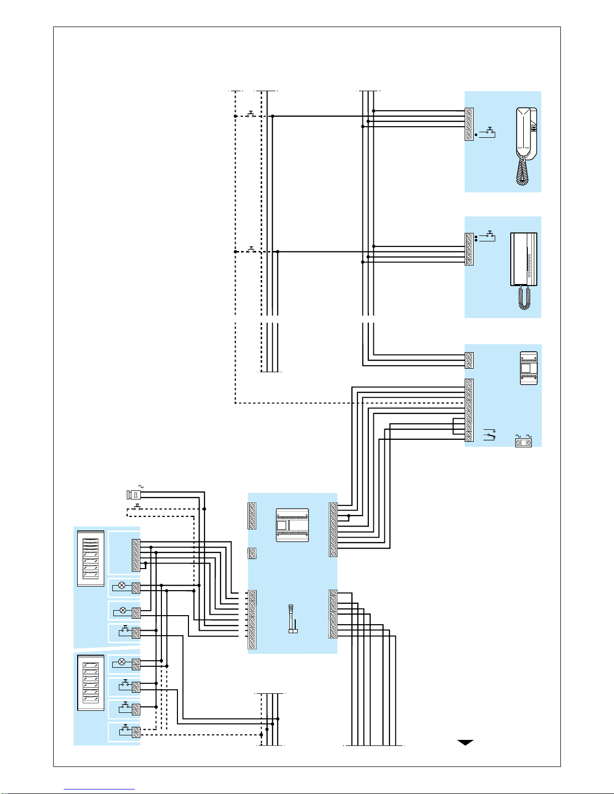
To enable this function, connect ter-
minal 8A of SI/200 selector to termi-
nal 8A on the power supplier installed
(A/200, A/241, etc.), figure 3.
In this case, connections cannot be
made for calls originating from inter-
nal floor landings.
Function of each terminal, figure 1
Terminal block B (to power supplier or
preceding selector)
5–11V supply voltage
21 +to entry panel
8call 1 common
8A call 2 common
11 audio to receiver
12 audio to entry panel
23 input 14V AC
13 door release solenoid
16 0V AC
24 engaged signal input
Terminal block E (to entry panel no. 1)
5–11V supply voltage
21 +to entry panel
8call common
11 audio to receiver
12 audio to entry panel
23 output 14V AC
13 door release solenoid
16 0V AC
24 engaged signal output
RS reset (1)
Eaudio enable
(1)Functions for combined (audio
and video entry systems) installa-
tions.
Terminal block F (to entry panel no. 2
or subsequent selector)
5–11V supply voltage
21 +to entry panel
8call common
11 audio to receiver
12 audio to entry panel
23 output 14V AC
13 door release solenoid
16 0V AC
24 engaged signal output
Terminal block G (services)
1call 1 input
2call 2 input
4engaged signal output (for resi-
dential systems)
5general reset
6enable output
Terminal block H (services)
1call 1 output
2call 2 output
SW jumpers functions, figure 1
(in ON position)
SW1 resetting of engaged entry
panels by replacing the hand-
set.
SW2 deactivation of call protection
and engaged signal.
NOTE. The selector is supplied with
SW1 jumper wired in.
When A/241 power supplier are
used (1+n installations), the SW1
jumper must be connected, figure
1.
Technical features
•Supply voltage: 11 V DC.
•Current demand: 45 mA max. (5
mA quiescent).
•Working temperature range: from
0 °C to +35 °C.
•Dimensions: 8 DIN units, low profi-
le module, figure 2.
The unit can be installed without
terminal covers into boxes provi-
ded with DIN rail (EN 50022).
Dimensions are shown in figure
2A.
It can also be surface mounted,
using the DIN rail supplied, but fit-
ted with terminal covers.
Dimensions are shown in figure
2B.