Bradbury Equipment H4441 Instruction Manual
H4441 / H4443 / H4541 / H4543
WHEEL-FREE
T61720
OPERATION AND MAINTENANCE INSTRUCTIONS
Bradbury Equipment
153-165 Bridge Street
GB- Northampton NN1 1QG
England
Tel. +44 (0) 1604 828 648
Date: 180918
Serial No:
Ref.: KM/LJE
Pages: 12
T61720
1
Main lift
Wheel-free
device
OPERATION AND MAINTENANCE INSTRUCTIONS
This lifting device is specially developed to lift motor cars and we strongly recommend not to lift any other
equipment with this automotive car lift.
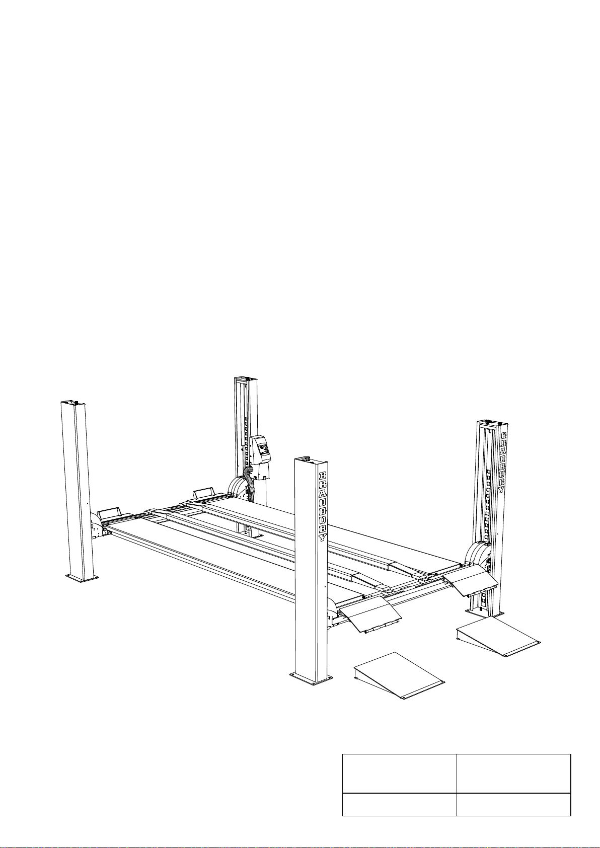
DESCRIPTION
The lift is an electro-hydraulic 4 post surface-mounted lift with capacity ranging from 3 to 5.2 t.
The lift consists of 2 pairs of posts connected with cross beams. The 2 platforms rest on the cross beams.
Furthermore, the lift is equipped with a wheel-free device; which consists of 2 cross beams placed on the outer
sides of the main cross beams and a pair of rails fitted to the wheel-free cross beams.
Platforms and cross beams for the main lift are raised and lowered bymeans of cables and a hydraulic cylinder
placed under one platform. The cables are attached to a yoke on the piston rod and run via cable pulleys to the four
post tops with an incorporated adjustment device.
The hydraulic pump unit and control box are placed on the front right post.
The lift is operated by means of pushbuttons showing the UP, DOWN and PARKING functions with indicators.
Furthermore, the control unit is fitted with a rotary switch for activation/deactivation of the wheel-free device.
Sound level measured at the control unit at a height of 1.6 m: max. 74 dB(A).

T61720
Revision:
2
INSTALLATION
In order to come up to your expectations now and in the future the lift must be installed in strict accordance with the
installation instructions and maintained according to our recommendations.
Contact your distributor for the name and address of the nearest authorized service shop.
FITTER INSTRUCTIONS
Install the lift in strict accordance with the original installation instructions which are included in each delivery.
The lift must be installed on solid foundation: concrete with minimum load capacity5500 N/m² and surface spot load
under posts 350 kN/m²; torque for expansion bolts attaching the posts: 25 Nּm.
There should be sufficient light for work on and under the lift. For the lift a lighting set is available as an optional
extra comprising four impact-proof, water-tight fluorescent tubes including cable (state model number).
Avoid installing the lift in rooms with danger of explosion.
WARNING: Person transportation is forbidden.
OPERATION
The lift should only be operated bytrained personnel !
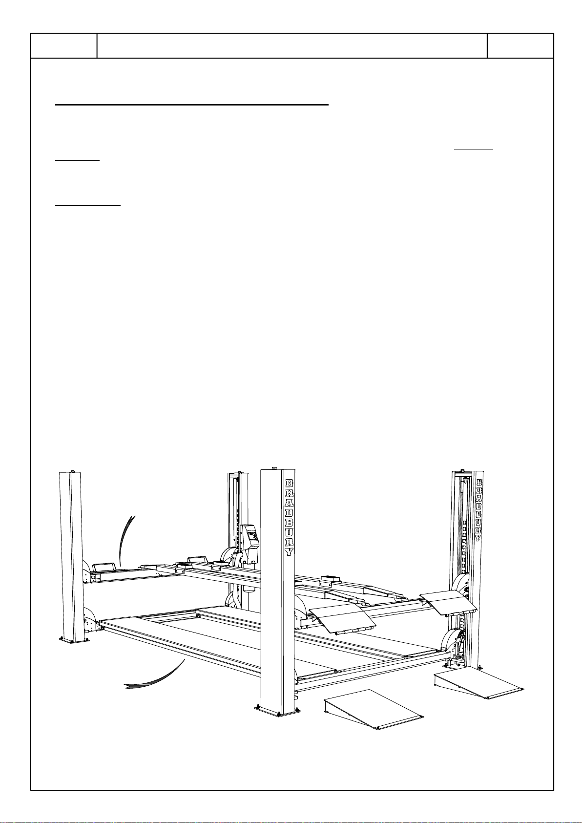
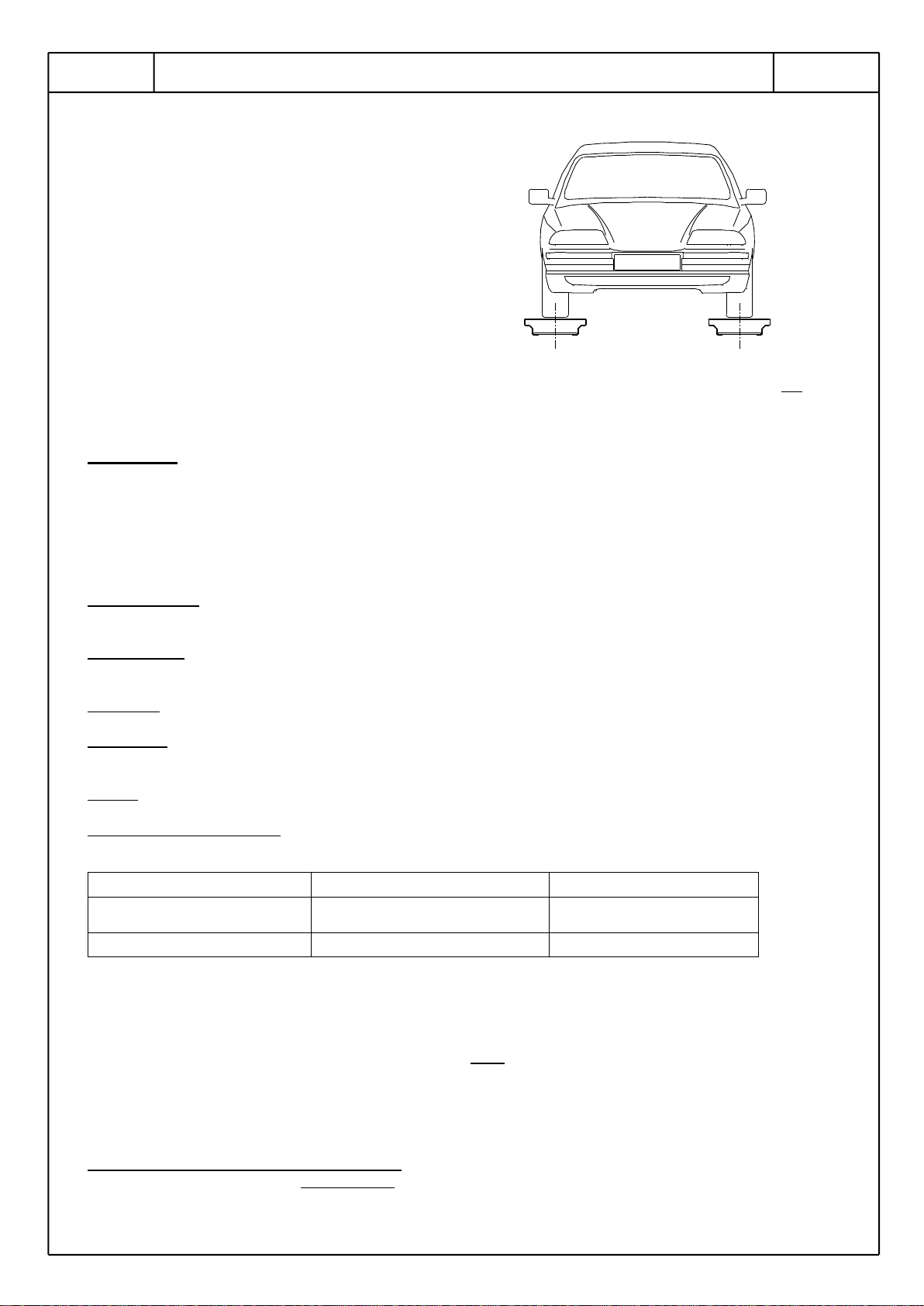
Approch
Before driving the vehicle on to the lift, check that platforms are parallel (the
same indicator position at both ends.
Raising
Push UP-button (motor starts): raise lift to a bit above required working
height.
Parking
Let go of UP-button and push PARK-button ➔ until platforms rest on all 4
ratchets.
Lowering
Check that no person or obstruction is under platforms. Push UP-button
shortly (to release the 4 ratchets) and then press DOWN-button . The lift
then lowers until the lift reaches automatic anti-toe trap device and the
lowering stops. Let go of DOWN-button and re-activate it after approx. 1
sec., the lowering continues until the lift reaches bottom position or until
pushbutton is not pressed any more.
NOTE: Always park lift (press ➔ button) before starting to work under it.
Operation Wheel-free:
When pushing UP-button , both platforms and wheel-free device are raised simultaneously. At the height wanted,
the rotaryswitch is activated and the wheel-free device parked. When pushing DOWN-button the platforms will
be lowered. When the job is finished, the platforms are raised till they reach the wheel-free device and the vehicle is
set off on the platforms. Deactivate the rotaryswitch; check that no persons or obstructions are under the platforms
and push UP-button shortly (to release the 4 ratchets). Push DOWN-button and the lift lowers until it reaches
the automatic anti-toe trap device and then stops. Let go of DOWN button; after app. 1 sec. reactivate it and the
lowering will continue until the lift reaches bottom position.
T61720
3
Adjust the platforms to the wheel track of the vehicle.
Place the vehicle centrally on the platforms compared
to the wheel track.
It is not allowed to operate the main lift while the vehicle is raised on one or two scissor jacks and it is not
fastened.
WARRANTY:
This lift is guaranteed for one year, covering faults due to manufacturing or material defects, provided that the
installation, operation and maintenance instructions are observed.
IMPORTANT ! Product liability accepted only if solely original spare parts have been used.
MAINTENANCE
Oil level check Check regularly the oil level in the reservoir under the pump. Fill up as necessary, correct oil
level is in the middle of the oil glass alternatively of dip stick.
Oil change First oil change after one year of operation, thereafter every 6 years.
Oil contents Approx. 8 l (for pump unit with built-on electric motor)
= 6.5 l (for pump unit with plunged electric motor)
Oil type See page 8
Lubrication and maintenance
Check and lubricate it at least once a month as follows:
Where
What
When
Axles for cable pulleys (with
grease nipples)
Grease
Once a month
Cables and rollers *)
Lubricating oil
Once a month
*) Check cables for wear
CLEANING
Cleaning of 4-post surface mounted lifts to prevent corrosion damages.
Corrosive fluids as brake fluid, oil, fuel or other solvents must be wiped off immediately, otherwise damage will
occur to the coating.
Special attention must be paid to the corrosive effect of salt in fall and winter periods.
The cleansing agents must not have any abrasive effect, nor contain solvents.
The lift must be cleaned at least once a week.
The lift must be cleaned with a non-corrosive cleansing agent.
T61720
Revision:
4
Clean and wipe the lift according to the following scheme:
When:
Where:
How:
Remarks:
Every week
Platforms
Clean and wipe
Wearing surfaces must be
slightly oiled
Drive-on ramps
Post / base plate
Alu rails for jack
Cross beams
Rails
Bradbury Equipment does not accept any claim concerning the paint peeling off or corrosion damages caused by
missing or insufficient cleaning or maintenance.
Repair of damages:
Repair of damages on the coating must be carried out immediately in order to minimize the extent of the repair.
The damages will typically be:
1. Damages which do not affect the metal surface but affects the coating itself
2. Damages going down into the metal surface.
Repairs:
Contact Bradbury Equipment for guidance.
Order number for repair paint is to be seen in the spare parts list and contains basic cleanser, primer and paint
together with instructions for repair of paint damages.
Please state RAL number of paint.
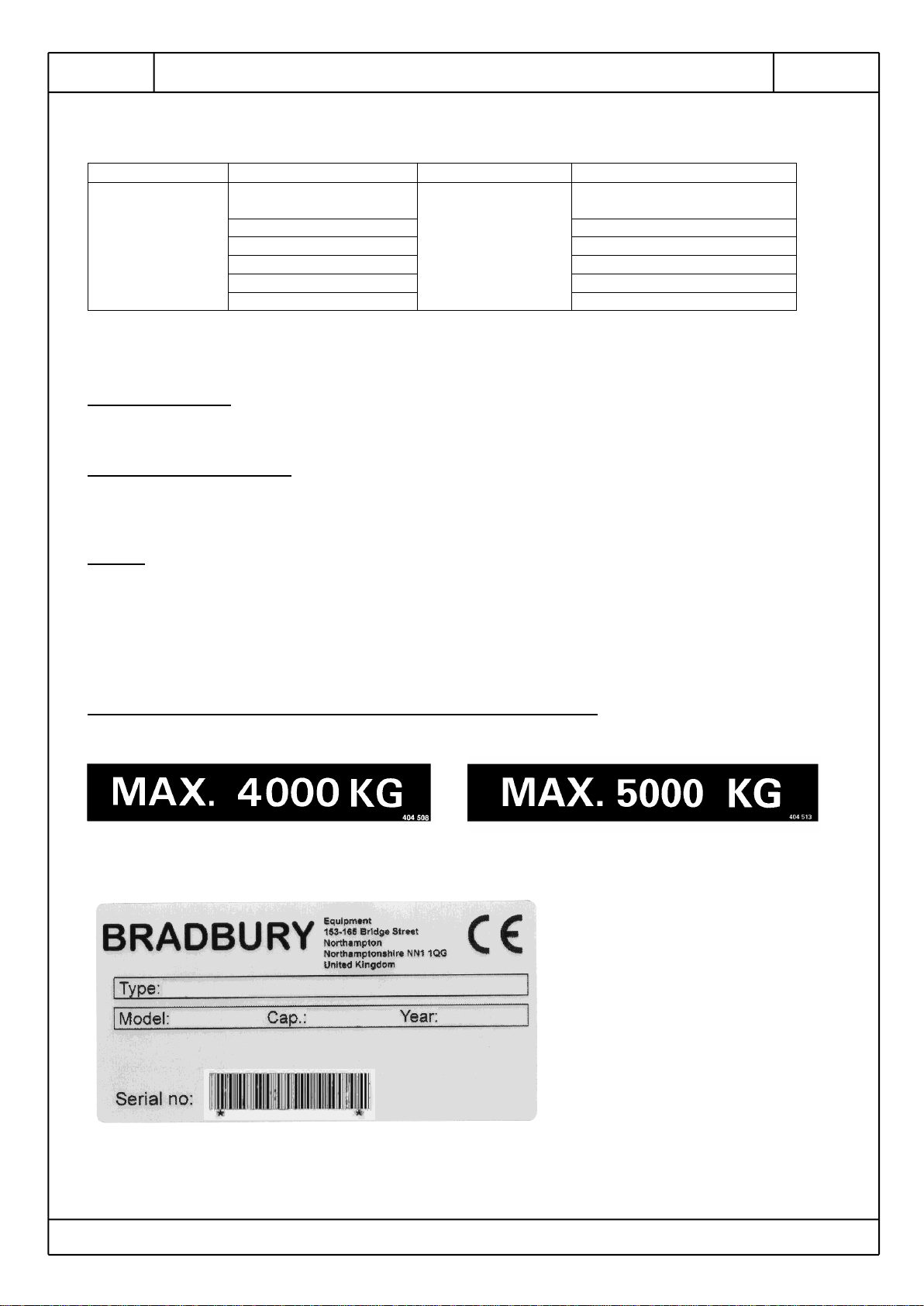
CHECK THAT THE NECESSARY LABELS ARE PLACED ON THE LIFT:
H4443 H4543
Name plate with the following data:
T61720
5
One of following load distribution labels:
H4443 H4543
Operation and maintenance instructions:
Alternative labels:
T61720
Revision:
6
ADJUSTMENT OF CABLES
Steel cables will stretch depending on the operational load and therefore require adjustment as follows:
a. Load the lift with approximately 2500 kg (5500 lbs).
b. Switch off air supply. Adjust wires to make the 4 ratchets engage simultineously when UP-button is activated.
c. Raise lift to top position. Check distance from underside of ratchet to underside of hole in ratchet rail; this
distance must be min. 20 mm.
d. Lower the lift to bottom position and check that the platforms rest against their stops. If not, adjustment of
cables is necessary.
CONTROL OF CABLES
Check cables for wear at the monthlylubrication intervals and replace as necessary (see below paragraph
concerning scrapping).
NOTE: The monthly lubrication with thin penetrating oil reduces cable wear and prolongs cable life appreciably.
GENERAL: At least once a year the cables must be checked-up by an authorized engineer.
Contact your distributor for the name and address of the nearest authorized service shop.
If documentation on cables and/or cable construction is required, please state the stamp on the cable lock. On
this request, copy of original certificate will be forwarded.
SCRAPPING OF CABLES
The steel cable must be discarded when:
•the cable is worn-down on more than10% wear of its nominal diameter
•an individual wire is worn more than 1/3 of the wire diameter
•the number of wire ruptures on a twisting length exceeds 10 on any spot of the cable
•the cable has a kink (pulled-out loop)
•the cable is flattened or cornered, even if there is no wire ruptures
•the wires in a strand are burst
•the cable is damaged by corrosion, even if there is no wire ruptures
•the cable has been damaged through chemical influence.
T61720
7
SERVICE
High pressure cylinder replacement - main lift
To be carried out bytrained personne. Please contract your dealer.
a. Raise the lift to the appropriate working height and allow the safety ratchets to engage.
b. Remove cables from yoke.
c. Remove lock nut and screw off yoke. If the piston rod is seized in the yoke, protect the rod surface with either
rubber or fibre before using a pipe wrench.
d. Remove pipe connection to the cylinder, push the piston rod in until the thread reaches the stuffing box and
remove the clip holding the cylinder to the platform.
e. Fit the new cylinder in the reverse order as above.
f. Raise the lift to the top and lower again to the floor to vent the new cylinder.
g. Test the lift under load and check pipe connections and stuffing box for possible oil leaks.
Replacement of packings in high pressure cylinder
To be carried out bytrained personnel. Please contact your dealer.
Spare parts kit
Spare parts kit for the cylinder contains above mentioned seals:
792425 (AC cylinder with external stuffing box)
792426 Piston seals kit
Spare parts
In order to ensure correct spare parts deliveries please state part number, designation, and quantity (to be seen
from spare parts list included in delivery) as well as lift serial number and year of production (to be seen from serial
number plate).
EMERGENCY LOWERING (In case of power cut-out) (not single phase lifts)
Turn mains on 0-position.
Bymeans of a jack raise one corner of the cross beam 3-4 mm. Pull out the ratchet and block it with a piece of
band. Repeat this in the 3 other corners.
Remove cover of pump unit.
Open carefully emergencylowering valve and lower lift carefully to bottom position. Close emergencylowering valve
again and re-fit cover.

T61720
Revision:
8
OIL SPECIFICATIONS
- Semi-hydraulic lift
(oil in lift cylinder)
- Full-hydraulic lift
- High-pressure No lift
- 4-post lift
- Mistral H
- Pit jack
- All-purpose lift
- Presses
- Scissor lift
- 2-post hydraulic
surface-mounted
- Servicemaster
Lubrication oil for
high-pressure lift
Additives:
Anti-foam, anti-corrosion, anti-oxidation
Other characteristics:
Water-separating
Viscosity:
(cSt=mm²/s)
75-120 cSt (40°C)
215 cSt (0°C)
32 cSt (40°C)
140 cSt (0°C)
22 cSt (40°C)
65 - 110 (40°C)
Viscosity index:
Min. 90
150
90
min. 70
Pour point:
Max. -10°C
Max. -10°C
Max. -10°C
Max. -10°C
ARAL
Aral vitam gf 100
Aral konit 30
AVIA
Abilub hydr.oil rsl 100
Avilub mk 2000
BP
Energol hlp 100
Bratran hv 32/shf 32
Bartran hv 22
Vannellus m 2030
CHEVRON
Hydraulic oil 100
Mechanism lps 32
EP industrial oil 68
GALP
Hidrolep 100
NR 30
ESSO STATOIL
Nuto hp 100
Hydraway hv 32
Hydraway hv 22
Protectway 32
FINA
Hydran tsx 100
Hydran ts 32
Hydran ts 22
Arusan 30
GULF - Q8
Q8 haydn 100
Q8 haydn 32
Q8 haydn 22
Q8 wagner 68
MOBIL
Mobil dte 18
Mobil dte 24
Mobil dte 22
Mobilarma 524
NYNÄS
Td 39 ex
Td 31 ex
OK
Ok hydraulic oil 65
Super hydr. oil 32
Ultima eph 68
SHELL
Tellus oil (S) 100
Tellus oil 32
Tellus oil 22
Remula x 20 w
NOROL
Hydraulikolje hm 100
Lagringsolje sae 20
TEXACO
Rando oil 150
Rando oil hd 32
Rando oil hd 22
Regal oil R&O 100
IGOL
Sonhodro 100/hydro 30
Relax
VALVOLINE
Ultramax hlp 100
Ultramax hvlp 32
Ultramax hvlp 22
Ultramax hlp 68
SUNOCO
Sonvis 8100 wr 100
Sunvis 832 wr-hv
Sunvis 822 we-hv
Sunfill 2630
ELF
Elf olna 100
Olna ds 32
Olna ds 22
Olna ds 100
CASTROL
Hyspin aws/awh 100
Hyspin awh 32
Hyspin aws 22
Rustilo 652

T61720
9
TROUBLE SHOOTING CHART
In case of breakdown check the following points:
1. Electricity cut
2. Main fuses
3. Motor starter
4. Electric motor
5. Cable fracture
6. Obstruction under lift
If these points are found in order but the lift is still not working, the safety system has probablybeen activated, and
the lift must not be started or repaired by unqualified staff. Contact the nearest authorized service shop.
Do not start repairing the lift until the main switch has been cut off.
Do not disconnect the safety system and do not operate the lift after breakdown and prior to repair.
SYMPTOM
CAUSE
REMEDY
A. Platforms no longer
horizontal when
hanging in cables
under load (approx.
1000 kg, 2200 lbs)
One or several cables
stretched
Adjust cables (see page 6)
B. Platforms no longer
horizontal when res-
ting on the ratchets
Incorrect adjustment
Adjust platforms and cross beams until they are horizontal.
Slacken nut under top plate for rail. Raise or lower ratchet
rails as required by means of adjustment bolts in top of
posts. After adjustment tighten lock nut under top plate for
rail. Ratchet rails should preferably be adjusted to lowest
possible position.
C. Activation of control
to lower lift from
topmost position
does not release
ratchets
One or more of the
cables have stretched
Adjust cables (see page 6).
D. Ratchets are not
released regardless
of parking height
Air source failure
Cure fault
Incorrect air pressure
Cure fault (min. 7 bar - max. 10 bar)
Platforms are not lifted
free from ratchet rails
Raise lift a little and lower.
One ratchet binding
Let an assistant operate UP-button so that lift ascends in
small jerks. Meanwhile pull ratchet free manually. Use pliers
or grips.
Defective solenoid
valve
Replace solenoid valve
E. Ratchets fail to
activate
Air system blocked
Strip and clean air system
F. Oil leakage
High pressure hose
defective
Replace hose
Leaks at fittings
Tighten
Cylinder seals
defective
Replace or renovate cylinder

T61720
Revision:
10
TROUBLE SHOOTING CHART (continued)
SYMPTOM
CAUSE
REMEDY
G. Unusually high
noise level
Pump worn
Replace pump
Lift overloaded
Max. load - see decals
Seal in high pressure
cylinder defective
Replace or renovate cylinder
Incorrect post position
Re-position posts according to installation instructions
Oil pressure release valve
out of adjustment
Adjust: 4 t = 230 bar
5.2 t = 320 bar
H. Lift cannot ascend
Overloading
Max. load - see decals
Insufficient pressure from
pump unit
See step M
I. Lift cannot descend
Pump does not start
See step L
One or more of the ratchets
still activated
Lift free from ratchet rails before lowering
Air system blocked
See step E
J. Lift cannot reach
topmost position
Insufficient oil in pump unit
Fill up oil until middle of oil glass/dip stick with
platforms at floor level. Oil type: see oil specifications
on page 8.
Incorrect cable adjustment
(too long)
See page 6
K. Platform descends
when ratchets are
not engaged
Leaks in hydraulic system
See step F
Lowering valve/ non-return
valve leaking (internal in the
pump unit)
Call authorized service engineer
L. Pump unit cannot
start
Electric failure
Check fuses.
Incorrect electric connections
Call authorized electrician
Fault in control box
Faulty electric motor
Defective pushbutton
Replace
M. Pump unit delivers
none or insufficient
pressure
Pump defective
Replace pump
Air in hydraulic system
Lower platforms to bottom position without load and
keep pressing DOWN-button for
approx. 20 sec.
Non-return valve or oil
pressure relief valve defective
(internal in pump unit)
Call authorized service engineer

T61720
11
CONTROL LIST FOR H4443/H4543
CHECK that the technical manuals are delivered with the lift (installation instructions, operation and
maintenance instructions, spare parts list, the EC-certificate of conformity, the electrical diagram in
the control box)
CHECK that all components are enclosed (see installation instructions T70729 and the accessory kit packing
list)
CHECK the lift for anypaint damages occured during transportation, or paint faults from the
production
Follow the installation instructions T70729 delivered with the lift and check the following points:
PLATFORMS AT
FLOOR LEVEL
Cross beams rest against their stops at floor level (all cables loose)
Posts are vertical in both directions
Right-hand platforms can be slid freely along cross beams
The two nuts for cables at top of posts are counter-tightened
Eccentric brake sensoryrollers are free to rotate on axles
Oil level in accordance with "oil level control" (oil level: middle of sight glass)
Important signs/decals:
* Max. capacity
* Maintenance + safety instructions (placed on control post)
* Several warning labels
* Name plate with CE-label
PLATFORMS
HANGING IN
RATCHETS AT
APPROX. 1 M'S
HEIGHT
High pressure hose fittings are tight
Armoured hose hangs freely as a "U" without strain
Air system checked for leaks
Platforms and cross beams are horizontal when lift is parked in ratchets
Cables are correctlyfitted (see installation drawing)
NON LOADED
LIFT
Excess-pressure valve is activated when platforms reach the topmost
position (audible)
LOADED LIFT
(APPROX. 1.5 T)
Platforms can be parked in the topmost ratchet holes (cable adjustment)
Platforms can be released and lowered from topmost ratchet holes
(tolerance approx. 20 mm)
Nylon slide blocks on cross beams must not touch (tolerance 0-0.5 mm)
(post adjustment –cross beam adjustment). Check that ratchet rail does not fret the
cross beam
Platforms horizontal when hanging in cables with load and no air connected.
If the lift is adjusted correctly, ONE click is to be heard from the ratchets when raising
the lift. If not - adjust.
INSTRUCTION
The end user has been thoroughlyinstructed in correct use and maintenance
CONCLUSION
Write any defects/faults on the enclosed note-scheme and return/fax a copy of this control
list (both pages 11 and 12) to:
Bradbury Equipment
153-165 Bridge Street
GB- Northampton NN1 1QG
England
Tel. +44 (0) 1604 828 648
RECEIPT
The above check-up has been made and the lift has been tested with a vehicle
(total weight kg)
Serial No. of lift: Installation date:
Responsible workshop manager: Fitter:

T61720
Revision:
12
NOTES
Other manuals for H4441
1
This manual suits for next models
3
Table of contents


