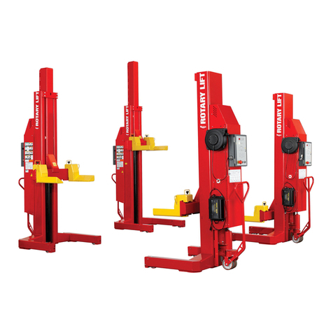
MAHA RGE User manual

Fehler! Verwenden Sie die Registerkarte 'Start', um Name dem Text zuzuweisen, der hier angezeigt werden soll.Fehler! Verwenden Sie
die Registerkarte 'Start', um Name dem Text zuzuweisen, der hier angezeigt werden soll.Fehler! Verwenden Sie die Registerkarte
'Start', um Name dem Text zuzuweisen, der hier angezeigt werden soll.
RGE
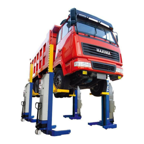
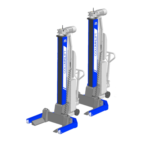
Mobile Column Lift
Original Operating Instructions
BA490801-en
Pos: 1 / Te chn is c he Dokum en tat i on/ H eb e tec hn ik /C OL UM N LI F T/ 49 08 0 1 R GE /BA / In ha lt: 49 08 T it elb i ld @ 42\mod_1431952788672_0.docx@ 2243711@ @ 1
Pos: 2 / -----F or m at---- -/MAN UEL LE R UM B RUC H Seite numb ruc h @ 0\m od_ 11 3 4403 5 776 87_ 0.d
Pos: 2 / -----F or m at---- -/MAN UEL LE R UM B RUC H Seite numb ruc h @ 0\m od_ 11 3 4403 5 776 87_ 0.d ocx @ 1 27 7 @ @ 1

2
BA490801-en
Pos: 3 /--- --For m at---- -/In ha ltsv er z eic hn is - 3 Eb e ne n @ 5\mod_ 11 688 67 4 410 46_ 7 5.do cx @ 72 9 20 @ @ 1
Contents
1Safety ......................................................................................................................5
1.1 Introduction......................................................................................................................................... 5
1.2 Symbols .............................................................................................................................................. 5
1.3 Intended Use....................................................................................................................................... 5
1.4 Inappropriate Use................................................................................................................................ 5
1.5 Requirements on Operating and Service Personnel............................................................................. 5
1.6 Safety Instructions for Commissioning................................................................................................. 6
1.7 Safety Instructions for Operation ......................................................................................................... 6
1.8 Safety Instructions for Servicing........................................................................................................... 6
1.9 What to Do in the Event of Defects or Malfunctions............................................................................. 6
1.10 What to Do in the Event of an Accident............................................................................................... 6
1.11 Safety Features ................................................................................................................................... 8
1.11.1 Locking Device.................................................................................................................................... 8
1.11.2 Braking Motor ..................................................................................................................................... 8
1.11.3 Phase Sequence Relay........................................................................................................................ 8
1.11.4 Thermal Overload Protection ............................................................................................................... 8
1.11.5 Safety Shutdown after Motor Overload................................................................................................ 8
1.11.6 Warning and Information Labels .......................................................................................................... 8
2Description...............................................................................................................9
2.1 General Information ............................................................................................................................. 9
2.2 Noise Emission.................................................................................................................................... 9
2.3 Specifications ...................................................................................................................................... 9
2.4 Sample Nameplate............................................................................................................................ 12
3Operation...............................................................................................................13
3.1 Handling / Moving the Columns ........................................................................................................ 13
3.2 Installing the Power Supply Unit ........................................................................................................ 14
3.3 Lift Positioning................................................................................................................................... 14
3.4 Controls ............................................................................................................................................ 16
3.5 Main Switch....................................................................................................................................... 17
3.6 Emergency Stop................................................................................................................................ 17
3.7 Operating Modes .............................................................................................................................. 17
3.7.1 Automatic Mode................................................................................................................................ 17
3.7.2 Single Mode ...................................................................................................................................... 18
3.7.3 Group Mode...................................................................................................................................... 19
3.7.4 Cable Remote Control....................................................................................................................... 19
3.8 Emergency-down Function, Mechanical............................................................................................ 20
3.9 RGE GPGU: Adjustment of Support Forks ........................................................................................ 21
3.10 Operation with more than 6 Columns ................................................................................................ 21
3.11 Transverse Beam for Semitrailers ...................................................................................................... 22
4Maintenance ..........................................................................................................23
3
BA490801-en
4.1 Annual Inspection.............................................................................................................................. 23
4.2 Care Instructions ............................................................................................................................... 23
4.3 Spare Parts ....................................................................................................................................... 23
4.4 Maintenance by the Operator ............................................................................................................ 24
4.4.1 Recirculating Ball Nut ........................................................................................................................ 24
4.4.2 Moving Gear...................................................................................................................................... 25
4.4.3 Options ............................................................................................................................................. 25
4.4.4 Thrust Washers ................................................................................................................................. 26
4.5 Setting the Hydraulic Jack................................................................................................................. 29
5Display Codes........................................................................................................30
6Service Lifetime......................................................................................................32
7Dismantling ............................................................................................................32
8Disposal.................................................................................................................32
9Contents of the Declaration of Conformity ..............................................................32
10 Company Information.............................................................................................33
Pos: 4 / -----F or m at---- -/MAN UEL LE R UM B RUC H Seite numb ruc h @ 0\m od_ 11 3 4403 5 776 87_ 0.d ocx @ 1 27 7 @ @ 1

4
BA490801-en
Pos: 5 / -----F or m at---- -/MAN UEL LE R UM B RUC H Seite numb ruc h @ 0\m od_ 11 3 4403 5 776 87_ 0.d ocx @ 1 27 7 @ @ 1

5
BA490801-en
Pos: 6 / Te chnisc he D okum entat ion/A lle Ger ä te/Üb erschr ifte n/Übers chr iften 1/ S/ Überschr ift 1: Sich erheit @ 6\mod_1174482399906_75.docx @ 76962@ 1 @ 1
1
Safety
Pos: 7 / Te chn isc he Dokum en tat ion/ A lle G erä te/ Übe rs chrif te n/ Über sc hr ift en 1.1/E/ Über sc hr if t 1.1: E inf ühr ung @ 6\m od_1174482219062_75.docx@ 76793 @ 2 @ 1
1.1
Introduction
Pos: 8 / Te chn isc he Dokum en tat ion/ A lle G er ä te/I nha lte/ S ic her he it/In ha lt : Ei nf ühr u ng Si cher hei t @ 6\mod_1175609639562_75.docx@ 87528@ @1
Thoroughly read this manual before operating the equipment and comply with the instructions.
Always display the manual in a conspicuous location.
Personal injury and property damage incurred due to non-compliance with these safety
instructions are not covered by the product liability regulations.
Pos: 9 / Te chnisc he D okum entat ion/A lle Ger ä te/Üb erschr ifte n/Übers chr iften 1 .1/S/ Über schri ft 1.1: Symbole @ 6\mod_1174482270875_75.docx @ 76865@ 2 @ 1
1.2
Symbols
Pos: 1 0 / Technische Do kumentatio n/Alle Geräte/ Inhalte/Si cherheit/In halt: Symbo leSic herheit @ 14\mod_1239866667866_75.docx @ 361518@ @1
Important safety instructions. Failure to comply with instructions could result in personal injury or
property damage.
Important information.
Pos: 1 1 / Techn ische Dokument ation/ Alle G erät e/Über schr iften/ Über schri ften 1.1/B/Über schrif t 1. 1: Bes timm un gsgemä ßer Geb rau ch @ 6\m od_117 6734 02220 3_75.d ocx @ 887 46 @ 2 @ 1
1.3
Intended Use
Pos: 1 2 / Tec hn is ch e Dokument ation/ Hebet echni k/CO LUMN LIFT/4 900 01 Rad greifer -Heb ebü hnen A lle/I nhal te/In halt: Bestimm ungs gemä ßer Geb ra uch RG -H BZ @ 11\mod_1227608538981_75.docx @ 275048@ @ 1
•This lift is to be used exclusively for the safe lifting of commercial and agricultural vehicles such
as trucks, buses, tractors etc. Observe the rated load capacity.
•The lift may not be modified without the express written consent of the manufacturer. In case of
non-compliance the declaration of conformity becomes void.
Pos: 1 3 / Techn ische Dokument ation/ Alle G erät e/Über schr iften/ Über schri ften 1.1/B/Über schrif t 1. 1: Bes timm un gswid riger G ebrauc h @ 18\m od_1255530265027_75.docx@ 471571 @ 2@ 1
1.4
Inappropriate Use
Pos: 1 4 / Tec hn isch e Dokume nta tio n/ Heb etechni k/- Ar ch iv -/ 00 H ebet echni k -Al le/In ha lte/I nhalt : Best immu ngsw idr iger G ebr auch HBZ @ 19\m od_1267188702628_75.docx@ 794843 @ @1
Any use other than described is inappropriate, for example:
•Climbing on the lift supports
•Transporting persons on the lift supports
•Usage as mobile work platform or for other lifting operations
Pos: 1 5 / Techn ische Dokument ation/ Alle G erät e/Über schr iften/ Über schri ften 1.1/A/Übersc hrif t 1. 1: A nford erun gen a n d as Bed ien ungs - und S erviceper sonal @ 34\mod_1380637497630_75.docx @ 1835413@ 2 @ 1
1.5
Requirements on Operating and Service Personnel
Pos: 16 / Techn ische Dokument ation/A lle Ger äte/I nhalte/ Sicher heit/In halt: Anf order unge n an das Bedie nungs- und Ser viceper sonal @ 35\mod_1390296255225_75.docx@ 1876648@ @1
All persons employed in the operation, maintenance, installation, removal and disposal of the
device must
•be at least 18 years old,
•be trained and instructed in writing,
•have read and understood this manual
•be on record as having been instructed in safety guidelines.
Pos: 1 7 / Techn ische Dokument ation/ Alle G erät e/Über schr iften/ Über schri ften 1.1/S/Übersc hrif t 1. 1: S icherhe itsv orschr ift en f ür d ie I nbe trieb nahm e @ 6\m od_1174482269156_75.docx@ 76838 @ 2 @ 1

6
BA490801-en
1.6
Safety Instructions for Commissioning
Pos: 1 8 / Te c hnisch e Do kument atio n/Heb etech nik/C OLUMN LIF T/4900 01 Rad grei fer-Heb ebü hnen A lle/I nhal te/In halt: Sicherhei tsvorsc hr iften für die I nbetr ieb nahme RG-HBZ @ 6\mod_1178094134921_75.docx @ 90757@ @ 1
•Use the lift on a hard, level surface only.
•The standard lift version may not be installed and commissioned in the vicinity of explosives or
flammable liquids.
Pos: 1 9 / Techn ische Dokument ation/ Alle G erät e/Über schr iften/ Über schri ften 1.1/S/Übersc hrif t 1. 1: S icherhe itsv orschr ift en f ür d en B etrieb @ 6\m od_1 174 48 226 8953_ 75.docx @ 76 826 @ 2 @ 1
1.7
Safety Instructions for Operation
Pos: 2 0 / Techn ische Dokument ation/ Hebet echni k/C OLUMN LIF T/4900 01 Rad grei fer-H ebebühnen A lle/Inhalte/ Inhalt: Sicher heitsvorsc hriften für de n Betrieb RG-HB Z @ 6\mod_1178094657921_75.docx@ 9 0770 @ @ 1
•Read the detailed operating manual.
•Lift operation by trained personnel over 18 years only.
•Do not exceed the rated load capacity per column as indicated on the lift nameplate.
•Ensure an unobstructed movement of lift and vehicle.
•After raising the vehicle briefly, stop and check the lift supports for secure contact with the
vehicle.
•Closely watch lift and vehicle during raising and lowering cycles.
•The working area which cannot be overviewed by the operator should be monitored by a
second person.
•When operating the lift in single or group mode, make sure the vehicle is not tilted.
•Do not allow anyone to stay in lift area during raising and lowering cycles.
•Do not allow anyone to climb on lift or inside raised vehicle.
•Keep lift and vehicle free of tools and parts.
•When using the lift outdoors, lower the vehicle and stop operation when the wind velocity
exceeds 6 m/s.
•Push the support forks completely under the wheels or lift points of the vehicle to be raised.
•Do not drive over or pinch electrical cables.
Pos: 2 1 / Techn ische Dokument ation/ Alle G erät e/Über schr iften/ Über schri ften 1.1/S/Übersc hrif t 1. 1: S icherhe itsv orschr ift en f ür Ser vicearbe iten @ 6\mod_1174482270640_75.docx @ 76850@ 2 @ 1
1.8
Safety Instructions for Servicing
Pos: 2 2 / Tec hnisch e Do kume ntat ion/Heb etech nik/C OLUM NLIF T/4900 01 Rad grei fer-Heb ebühnen All e/Inhalte/I nhalt: Sicher heitsvorsc hriften für Ser vicearbei ten RG-HBZ @ 6\mod_ 11 7 8095 2 27 937_ 7 5.d oc x @ 907 93 @ @ 1
•Service work may be done by authorized service technicians only.
•Turn off and padlock the main switch before doing any repair, maintenance or setup work.
•Disconnect the mains plug before opening the control box.
•Work on the electrical equipment may be done by service technicians or certified electricians
only.
•Ensure that ecologically harmful substances are disposed of only in accordance with the
appropriate regulations.
•Do not use high pressure or steam jet cleaners. Use of caustic cleaning agents may damage
the lift.
•Do not replace or override the lift safety devices.
Pos: 2 3 / Techn ische Dokument ation/ Alle G erät e/Über schr iften/ Über schri ften 1.1/V/Übers chr ift 1 .1: Ver hal ten im Störfall @ 6\mod_1178097008375_75.docx @ 90829@ 2 @ 1
1.9
What to Do in the Event of Defects or Malfunctions
Pos: 2 4 / Techn ische Dokument ation/ Hebetech nik/- A rc h iv -/ 00 H ebet echni k -Al le/ I nh a lte/ I nha lt : V erh a lte n im St örf a ll H BZ @ 19\m od_1267177095494_75.docx@ 794570@ @ 1
•In case of defects or malfunctions such as uncontrolled lift movement or deformation of the
superstructure, support or lower the lift immediately.
•Turn off the main switch and secure it against unauthorized usage. Contact service.
Pos: 25 /Techn ische Dokume ntation/Al le Geräte/Über schrift en/Überschr iften 1.1/V /Überschr ift 1.1: Verhal tenb ei Unfällen @ 1 9\mod_12 6 7177245337_75.docx @ 794600@ 2 @ 1
1.10
What to Do in the Event of an Accident

7
BA490801-en
Pos: 26 /Techn ische Dokume ntation/Al le Geräte/Inh alte/Sicher heit/Inhal t: Verhalten bei U nfällen @ 34\mod_1381128804654_75.docx@ 1837123@ @ 1
•The injured person is to be removed from the danger area. Find out where dressing and
bandages are kept. Seek first-aid.
•Provide first-aid (stop bleeding, immobilise injured limbs), report the accident and seal off the
accident site.
•Immediately report any accident to your supervisor. Make sure a record is kept of every
occasion first-aid is provided, e.g. in an accident book.
•Remain calm and answer any questions that may arise.
Pos: 2 7 /----- Form a t-----/M A N UE L LER UMB R UCH Sei ten um b r uch @ 0\m od_1134403577687_0.docx @ 1277@ @ 1

8
BA490801-en
Pos: 2 8 / Tec hn isch e Dokume nt at ion/ Al le G er ät e/Üb ers c hr iften/ Übe rs chri fte n 1.1/S/ Über sc hr if t 1. 1: S ic her he its ei nric ht un ge n @ 6\mod_ 11744 83324 765_ 75.do cx @ 77103 @ 2 @ 1
1.11
Safety Features
Pos: 2 9 / Techn ische Dokument ation/ Hebet echni k/C OLUMN LIF T/4900 01 Rad grei fer-Heb ebü hnen A lle/I nhal te/Inhal t: S icher heitse inrich tung en RG-H BZ @ 17\mod_1250235608088_75.docx@ 427993@ 333333@ 1
1.11.1
Locking Device
The locking device serves to prevent inadvertent lowering motions caused by gear,
load nut or lifting screw failure. The carriage is blocked by safety wedge (1) and
counterwedge (2).
1.11.2
Braking Motor
The motors are equipped with AC spring pressure brakes. Once the motors
are switched off, the brakes prevent any further movements.
1.11.3
Phase Sequence Relay
The phase sequence relay in the power supply unit ensures safe and
independent operation.
1.11.4
Thermal Overload Protection
Overload protection via electronically monitored thermoswitches.
1.11.5
Safety Shutdown after Motor Overload
The motor load is permanently monitored by the control PCB. If an overload of
≥15 %
occurs, the
system will switch off automatically. In this case the lift cannot be raised any more, but it can be
normally lowered to bottom position.
1.11.6
Warning and Information Labels
Do not change or remove the warning and information labels. Order replacement for defective
labels.
Pos: 3 0 /----- Form a t-----/M A N UE L LER UMB R UCH Sei ten um b r uch @ 0\m od_1134403577687_0.docx @ 1277@ @ 1

9
BA490801-en
Pos: 31 /Techn ische Dokument ation/Alle Ger äte/Übersc hr ift en/ Üb er schr i fte n 1/ B/ Üb er schr if t 1: Beschr e ibun g @ 6\mod_1174482271453_75.docx @ 76889 @1 @ 1
2
Description
Pos: 3 2 / Techn ische Dokument ation/ Alle G erät e/Über schr iften/ Über schri ften 1.1/A/Übersc hrif t 1. 1: A llgem eines @ 6\mod_1182865005781_75.docx @ 97736@ 2 @ 1
2.1
General Information
Pos: 3 3 / Techn ische Dokument ation/ Papi erkorb /Heb etech nik/In halt : B eschr eibung Allgeme ines RGE @ 17\mod_1250243858131_75.docx@ 428020@ @ 1
The mobile column lifts of the RGE series are produced as wheel engaging or universal lifts.
Depending on the version, the lift system consists of 2 or 4 columns and can be expanded to 6
columns in the standard version.
The lift can be expanded up to 12 columns when using a special power supply unit.
All components are easily accessible under the lifted vehicle due to a generous maximum lifting
height of 1750 mm.
The lift is a mobile unit whereby the columns can be substituted with stands when vehicles are to
be worked on for a longer period of time. The lifting columns are free to be used on other vehicles.
Pos: 3 4 / Techn ische Dokument ation/ Alle G erät e/Über schr iften/ Über schri ften 1.1/L/Über schrif t 1. 1: Lär mem issi on @ 13\mod_1236767272078_75.docx @ 354579@ 2 @ 1
2.2
Noise Emission
Pos: 3 5 / Techn ische Dokument ation/ Hebet echni k/- A rc h iv -/ 00 H ebet echni k -Al le/ I nh a lte/ I nha lt : S cha lld r u ckp e gel < 70 dB(A) @ 1 4\mod_1241593887290_75.docx@ 371013@ @1
The sound pressure level is lower than 70 dB(A) in the working area of the operator.
Pos: 3 6 / Techn ische Dokument ation/ Alle G erät e/Über schr iften/ Über schri ften 1.1/T/Über schri ft 1.1: Technis che D aten @ 7\mod_1184075526343_75.docx @ 99711@ 2 @ 1
2.3
Specifications
Pos: 3 7 / Techn ische Dokument ation/ Hebet echni k/C OLUMN LI F T/4 90 8 01 RG E/ BA/ I nh alt : 4 90 8 Te c hn isc he Date n ( Tab e lle ) @ 18\mod_1256046112218_75.docx @ 480360@ @1
RGE
RGE GPGU
RGE T
Load capacity per column 7500 kg 7500 kg 5000 kg
Full travel 1750 mm 1750 mm 1750 mm
Raising / Lowering time 113 s 113 s 113 s
Raising speed 0.92 m/min 0.92 m/min 0.92 m/min
Tyre diameter 900…1250 mm --- 600…2000 mm
Motor power 1.5 kW 1.5 kW 1.5 kW
System of protection IP 54 IP 54 IP 54
Supply voltage 3~ 380/220 V; 50 Hz 3~ 400 V; 50 Hz 3~ 400 V; 50 Hz
Net weight per column 452 kg 502 kg 542 kg
Surface load 0.5 N/mm20.5 N/mm20.5 N/mm2
Pos: 3 8 / Techn ische Dokument ation/ Hebet echni k/- A rc h iv -/ 00 H ebet echni k -Al le/I n ha lte/I nfo!/ In ha lt : I nf o - B etri ebswar mer Z ustand / Te chn. Ä nder ung en H BZ @6\mod_1177427042703_75.docx@ 90160@ @ 1
The properties indicated apply to lifts running at operating temperature.
Specifications are subject to change without notice.
Pos: 3 9 /----- Form a t-----/M A N UE L LER UMB R UCH Sei ten um b r uch @ 0\m od_1134403577687_0.docx @ 1277@ @ 1

10
BA490801-en
Pos: 40 /Techn ische Dokume ntation/Pap ierkorb/ Hebetechnik/ Inhalt: Tec hnische Daten (B ilder) RGE/R GEG PGU @ 18\mod _ 125 60 396 61 310_ 0. d ocx @ 4 79 921 @ @ 1
RGE
RGE GPGU
Pos: 41 / -----For m a t-----/M AN UE L LE R UM BR UC H S e i ten um b ru ch @ 0\m od_1134403577687_0.docx @ 1277@ @ 1

11
BA490801-en
Pos: 42 /Techn ische Dokume ntation/Pap ierkorb/ Hebetechnik/ Inhalt: Tec hnische Daten (B ilder) RGE T @ 18\mod_1256042847810_0.docx @ 479948@ @ 1
RGE T
Pos: 4 3 /----- Form a t-----/M A N UE L LER UMB R UCH Sei ten um b r uch @ 0\m od_1134403577687_0.docx @ 1277@ @ 1

12
BA490801-en
Pos: 4 4 / Techn ische Dokument ation/ Alle G erät e/Über schr iften/ Über schri ften 1.1/T/Über schri ft 1.1: Typensch ild-M ust er @ 11\mod _ 122 76 222 06 0 96_ 75.d ocx @ 27 5574 @ 2 @ 1
2.4
Sample Nameplate
Pos: 4 5 / Techn ische Dokument ation/ Hebet echni k/C OLUMN LIF T/4900 01 Rad grei fer-H ebebü hnen A lle/Inh alte/In halt: Typ ensch ild-M uster RG-H BZ MAHA @ 2 4\mod_1309945137131_75.docx @ 1021484 @ @ 1
MOBILE COLUMN LIFT
Ser.No. / Date of Production: ***
Project: ***
Type: ***
Charging Voltage: ***
Operating Voltage: ***
Net weight per column: ***
Load capacity per column: ***
System of Protection: ***
WEEE Reg. No. ***
Pos: 4 6 /----- Form a t-----/M A N UE L LER UMB R UCH Sei ten um b r uch @ 0\m od_1134403577687_0.docx @ 1277@ @ 1

13
BA490801-en
Pos: 4 7 / Techn ische Dokument ation/ Alle G erät e/Über schr iften/ Über schri ften 1/B/Übers chrift 1: Bed ienu ng @ 6\mod_1174482271218_75.docx@ 76877 @ 1 @ 1
3
Operation
Pos: 4 8 / Techn ische Dokument ation/ Alle G erät e/Über schr iften/ Über schri ften 1.1/T/Über schri ft 1.1: Transpor t / Verschiebe n v on H ubs äu le n @ 12\mod_1231486358029_75.docx @ 300405@ 2 @ 1
3.1
Handling / Moving the Columns
Pos: 4 9 / Techn ische Dokument ation/ Hebet echni k/C OLUMN LIF T/4908 01 RGE/ BA/ Inhal t: 4 908 Tr ansp ort/Ver sch ieben ( Bilder ) @ 12\mod_1231486938020_0.docx @ 300505@ @ 1
Pos: 50 /Techn ische Dokume ntation/Pap ierkorb/ Hebetechnik/ Inhalt: Trans port/Ver schieb en (T ext) RGE @ 12\mod_1231486726149_75.docx@ 300480@ @ 1
Screw a lifting-eye bolt M16 into the tap hole on the motor plate of the column. Insert a chain or
strap through the ring and lift the column using a hoist or forklift.
Close hydraulic valve by putting valve lever in position 3.
Pump with handle to raise the moving gear. Move column to desired position.
To lower the moving gear, open the hydraulic valve by putting the valve lever in position 1. The
column is ready for operation.
Position 2 is the neutral position.
Pos: 5 1 /----- Form a t-----/M A N UE L LER UMB R UCH Sei ten um b r uch @ 0\m od_1134403577687_0.docx @ 1277@ @ 1

14
BA490801-en
Pos: 5 2 / Techn ische Dokument ation/ Alle G erät e/Über schr iften/ Über schri ften 1.1/A/Übersc hrif t 1. 1: A ufsteck en d er Versorg un gse in he it @ 2 4\mod_1310375912170_75.docx@ 1022557 @ 2 @ 1
3.2
Installing the Power Supply Unit
Pos: 5 3 / Techn ische Dokument ation/ Hebet echni k/C OLUMN LIF T/4908 01 RGE/ BA/ Inhal t: 4 908 Ver s orgun gseinh eit ( Bi ld) @ 12\mod_1231747186755_0.docx @ 300870@ @ 1
Pos: 5 4 / Tec hnisch e Dokumentat ion/ Papi erkorb /H ebete chnik/I nha lt: Ver sor gu ngsei nheit RGE (T ext) @ 12\mod_1231747307958_75.docx@ 300895@ @1
Attach the power supply unit (V) to the left-hand sidewall of the control unit (B), as seen from the
controls, to ensure easy accessibility of the main switch.
Pos: 55 /Techn ische Dokument ation/Alle Ger äte/Übersc hriften/ Überschrifte n 1.1/A/Übersc hrift 1.1: Aufs tellen der Hebeb ühne @ 12\mod_1231747750802_75.docx @ 30 1020 @ 2 @ 1
3.3
Lift Positioning
Pos: 5 6 / Tec hnisch e Dokumentat ion/ Papi erkorb /H ebete chnik/I nha lt: A nsch lusss ch ema RGE( Tex t) @ 12\mod_1231748550599_75.docx @ 301095@ @ 1
Connection Diagram
B
Control Unit
1
Connecting Cable
V
Power Supply Unit
2
Dummy Plug
E
Input Terminal
3
Mains Plug
A
Output Terminal
Pos: 5 7 / Techn ische Dokument ation/ Hebet echni k/C OLUMN LIF T/4908 01 RGE/ BA/ Inhal t: 4 908 A nsc hlusss chema ( B ilder) @ 12\mod_1231748798771_0.docx@ 301120@ @1

15
BA490801-en
Pos: 5 8 / Tec hn ische Dokument atio n/Pap ier korb/ Heb etech nik/I nha lt: A ufst ellen der Heb ebü hn e ( Tei l 1) @ 12\mod_1231748934630_75.docx @301145 @ @1
•Use the lift on a hard, level surface only, preferably concrete.
•Apply the parking brake after positioning the vehicle.
•Push the support forks completely under the wheels/lift points of the vehicle.
•Attach the power supply unit (V) to the control unit (B) of the column closest to the mains
socket.
•Interconnect the columns using connecting cables (1) between input terminals (E) and output
terminals (A). Connect a dummy plug or the remote control (2) to the output terminal of the last
column.
Pos: 5 9 / Techn ische Dokument ation/ Hebet echni k/- A rc h iv -/ 00 H ebet echni k -Al le/In halte/ Warn ung!/I nhal t: Warnung- Verlegte K abel @ 12\mod_1231749063771_75.docx @ 301170@ @1
Do not drive over or pinch electrical cables.
Pos: 6 0 / Techn ische Dokument ation/ Hebet echni k/- A rc h iv -/ 00 H ebet echni k -Al le/I n ha lte/I nfo!/ In ha lt : I nf o - A ufstellen der Hebeb ühne @ 12\mod_1231749115349_75.docx@ 301205@ @1
Secure the connecting cable plugs using the safety clamps.
The plugs and terminals are coded.
Pos: 6 1 / Tec hn ische Dokument atio n/Pap ier korb/ Heb etech nik/I nha lt: A ufst ellen der Heb ebü hn e ( Tei l 2) @ 12\mod_1231749215146_75.docx @301230 @ @1
•Connect the mains plug (3) of the master column with the 400 V mains socket. Recheck the
electrical connections.
•Once the main switch is turned on, the lift is ready for operation.
Pos: 6 2 /-----F orm a t-----/ MA N UE L LE R UM BR UC H S e i ten um b ru ch @ 0\m od_1134403577687_0.docx @ 1277@ @ 1

16
BA490801-en
Pos: 6 3 / Techn ische Dokument ation/ Alle G erät e/Über schr iften/ Über schri ften 1.1/B/Über schrif t 1. 1: Bed ien elemen te @ 13\mod_ 123 7975099 177_ 75.do cx @ 359 008 @ 2 @ 1
3.4
Controls
Pos: 6 4 / Techn ische Dokument ation/ Hebet echni k/C OLUMN LIF T/4908 01 RGE/ BA/ Inhal t: 4 908 Bed ien elemen te ( Bilder ) @ 25\mod_1319463749099_0.docx @ 1065861@ @ 1
Pos: 65 /Techn ische Dokument ation/Papi erkorb/H ebetechnik/In halt: Bedie nelemente RGE ( Text) @ 12\mod_1231490810014_75.docx @ 300760@ @ 1
V
Power Supply Unit
B
Control Unit
1
Main Switch
2
LED Display
Indicates operating and error states.
3
Selector Button (on Control Unit)
Use this button to select between: Automatic / Single / Group mode
4
Seven-Segment Display (on Control Unit)
Indicates operating and error codes.
5
RAISE Button (on Control Unit)
Press and hold this button to raise the lift. Lift stops once button is released or upward travel
stop is reached.
6
LOWER Button (on Control Unit)
Press and hold this button to lower the lift. Lift stops once button is released or downward
travel stop is reached.
7
Emergency Stop Button (on Control Unit)
In case of emergency press this button to disconnect the lift from the mains supply.
Pull out the button to make the lift ready for operation.
Pos: 6 6 /----- Form a t-----/M A N UE L LER UMB R UCH Sei ten um b r uch @ 0\m od_1134403577687_0.docx @ 1277@ @ 1

17
BA490801-en
Pos: 6 7 / Techn ische Dokument ation/ Alle G erät e/Über schr iften/ Über schri ften 1.1/H/Über schr ift 1 .1: Haup tsch alter @ 6\m od_11 77592 8583 12_75.d ocx @ 90 635 @ 2 @ 1
3.5
Main Switch
Pos: 6 8 / Techn ische Dokument ation/ Hebet echni k/- A rc h iv -/ 00 H ebet echni k -Al le/ I nh a lte/ I nha lt : H a upts c ha lter mit Not-A us-Funkt ion H BZ @ 22\m od_1295874475528_75.docx@ 964591@ @ 1
The main switch is used as emergency switch. In case of emergency turn it to position 0.
•Main switch in position 0: Power supply is interrupted
•Main switch in position 1: Lift is ready for operation
•When in position 0, the main switch can be protected against tampering
by means of a padlock.
Pos: 6 9 / Techn ische Dokument atio n/Alle Geräte/Über sc hriften/ Über schri ften 1.1/N/Über schr ift 1 .1: N ot-H a lt-S chalter @ 12\m od_1 23176 26854 15_75.d ocx @ 3 02085 @ 2 @ 1
3.6
Emergency Stop
Pos: 7 0 / Techn ische Dokument ation/ Papi erkorb /Heb etech nik/In halt : No t-Ha lt @ 1 2\mod_1231763835049_75.docx@ 302215@ @1
In case of emergency push the emergency stop button to stop the lift movement immediately.
Pos: 7 1 / Techn ische Dokument ation/ Hebet echni k/- A rc h iv -/ 00 H ebet echni k -Al le/I n ha lte/I nfo!/ In ha lt : I nf o - No t-Halt @ 12\mod_1231764019369_75.docx @ 302260@ @ 1
To make the lift ready for operation, unlock the emergency stop button and switch off the lift briefly
using the main switch.
Pos: 7 2 / Techn ische Dokument ation/ Alle G erät e/Über schr iften/ Über schri ften 1.1/B/Über schrif t 1. 1: Be triebs ar ten @ 14\mod_ 124 22826 63093 _75.d ocx @ 375 477 @ 2 @ 1
3.7
Operating Modes
Pos: 7 3 / Techn ische Dokument ation/ Alle G erät e/Über schr iften/ Über schri ften 1.1.1/A/ Über s c hr if t 1.1 .1 : A ut om a tik-Be t rie b @ 1 2\mod _12 31753 24100 5_75.d ocx @ 30 1580 @ 3 @ 1
3.7.1
Automatic Mode
Pos: 7 4 / Techn ische Dokument ation/ Papi erkorb /Heb etech nik/In halt : A utomat ik-Betr ieb RGE @ 12\mod_1231753348068_75.docx @ 301635 @ @ 1
Select "Automatic mode" by pressing this button on each column.
Activation of this operating mode is indicated by the letter A on the seven-
segment display.
Use these buttons on the control unit to raise or lower the lift.
Pos: 7 5 / Tec hn is che Do kumentat ion/Hebetech nik/- Ar ch iv -/ 00 H ebet ech nik -A lle/ In ha lte/ I nfo!/ In ha lt : Inf o - Au tomat ikbetr ieb RGE @ 12\mod_1231754332521_75.docx@ 301660@ @ 1
After switch-on the lift is in automatic mode.
Pos: 7 6 /----- Form a t-----/M A N UE L LER UMB R UCH Sei ten um b r uch @ 0\m od_1134403577687_0.docx @ 1277@ @ 1

18
BA490801-en
Pos: 7 7 / Techn ische Dokument ation/ Alle G erät e/Über schr iften/ Über schri ften 1.1.1/S/Über sc hrift 1.1.1: S ingle-B etrieb @ 12\mod_1231750604943_75.docx@ 301400@ 3 @ 1
3.7.2
Single Mode
Pos: 7 8 / Techn ische Dokument ation/ Hebet echni k/- A rc h iv -/ 00 H ebet echni k -Alle/Inhalte/Warnung!/Inhalt:Warnung- Einz elb e tr ieb RG @ 20\mod_1268321800281_75.docx @ 824738@ @1
When operating the lift in Single mode, make sure the vehicle is not tilted. Otherwise the vehicle
may fall off the lift!
Pos: 7 9 / Techn ische Dokument ation/ Papi erkorb /Heb etech nik/In halt : S ingle-B etrieb (mit War nun g) RGE @2 0\mod_1268321049708_75.docx @ 824703@ @1
Select "Single mode" by pressing this
button on the desired column.
Activation of this operating mode is
indicated by the lit LED on the selector
button and the letter S on the seven-
segment display.
The columns not in Single mode are
temporarily inoperative. This is indicated by
the letter A flashing on the seven-segment
display.
Use these buttons to raise or lower the lift.or
Pos: 8 0 / Tec hn is che Do kumentat ion/Hebetech nik/- Ar ch iv -/ 00 H ebet ech nik -A lle/ In ha lte/ I nfo!/ In ha lt : Inf o - Ver schied ene H ubs äule n RGE @ 12\mod_1231755449651_75.docx @ 301710@ @ 1
The single mode can also be used for several columns simultaneously
Pos: 8 1 / Techn ische Dokument ation/ Hebet echni k/- A rc h iv -/ 00 H ebet echni k -Al le/I n ha lte/I nfo!/ In ha lt : I nf o - S i n gle -Be tr ieb RGE @ 12\mod_1231756197190_75.docx @ 301735@ @1
Height offsets between individual columns will be maintained after switch-over to automatic mode.
The offset can be removed either
– by equalizing the carriages in single mode or
– by lowering all carriages to bottom position in automatic mode.
•Lift switches off once first carriage reaches upward travel stop.
Pos: 8 2 /----- Form a t-----/M A N UE L LER UMB R UCH Sei ten um b r uch @ 0\m od_1134403577687_0.docx @ 1277@ @ 1

19
BA490801-en
Pos: 8 3 / Techn ische Dokument ation/ Alle G erät e/Über schr iften/ Über schri ften 1.1.1/G/Über sc hrift 1 .1.1: Gr upp en-B etrieb @ 12\mod_1231756478332_75.docx@ 301 760 @ 3 @ 1
3.7.3
Group Mode
Pos: 8 4 / Techn ische Dokument ation/ Hebet echni k/- A rc h iv -/ 00 H ebet echni k -Alle/Inhalte/Warnung!/Inhalt:Warnung- GruppenbetriebRG @ 20\mod_1268321843218_75.docx @ 824769@ @1
When operating the lift in Group mode, make sure the vehicle is not tilted. Otherwise the vehicle
may fall off the lift!
Pos: 8 5 / Techn ische Dokument ation/ Papi erkorb /Heb etech nik/In halt : Gr uppe n-Betr ieb ( mit W arnung) RGE @ 2 1\mod_1281958619825_75.docx @ 879733@ @1
2 sec
Select "Group mode" by pressing and
holding this button for approx. two
seconds.
Activation of this operating mode is
indicated by the lit LED on the selector
button and the letter G on the seven-
segment display.
The columns not in Group mode are
temporarily inoperative. This is indicated by
the letter A flashing on the seven-segment
display.
Use these buttons to raise or lower the lift.or
Pos: 8 6 / Techn ische Dokument ation/ Alle G erät e/Über schr iften/ Über schri ften 1.1.1/K/Üb erschr ift 1.1.1: Kab elfer nbed ienun g @ 12\mod_1231757725696_75.docx@ 301860 @ 3 @1
3.7.4
Cable Remote Control
Pos: 8 7 / Techn ische Dokument ation/ Papi erkorb /Heb etech nik/In halt : K abelf ernbedien ung RGE @ 12\mod_1231758115175_75.docx @ 301885@ @ 1
A remote control (model TCNA 10-2) is optionally available.
The RAISE, LOWER and Emergency Stop buttons have the same functions as the corresponding
buttons on the column control units.
Pos: 8 8 / Techn ische Dokument ation/ Hebet echni k/- A rc h iv -/ 00 H ebet echni k -Al le/I n ha lte/I nfo!/ In ha lt : I nf o - K abe lf er nb edie nu ng RGE @ 1 2\mod_1231760974987_75.docx@ 301950@ @1
Except for the emergency stop button, the remote control is not usable in single mode.
Pos: 8 9 /----- Form a t-----/M A N UE L LER UMB R UCH Sei ten um b r uch @ 0\m od_1134403577687_0.docx @ 1277@ @ 1

20
BA490801-en
Pos: 9 0 / Techn ische Dokument ation/ Alle G erät e/Über schr iften/ Über schri ften 1.1/N/Über schr ift 1 .1: No tab-Funktion,m echanisch@15\mod _124 52509 2128 6_75.d ocx @ 390 749 @ 2 @ 1
3.8
Emergency-down Function, Mechanical
Pos: 9 1 / Techn ische Dokument ation/ Hebet echni k/- A rc h iv -/ 00 H ebet echni k -Alle/Inhalte/Warnung!/Inhalt:Warnung- Manue ll es Ab se nke n n ur durc h g es c hultes Pers ona l @ 6\mod_1180962217687_75.docx @ 95217@ @ 1
Authorized personnel only! Do not restart the lift before the error has been remedied.
Pos: 9 2 / Techn isch e Do kume nt atio n/Papi er korb /Heb ete chnik/I n halt : M a nuel les Abs enk en RGE/RGA @ 24\mod_1310108278807_75.docx @ 1022148@ @1
In case of power failure or defects the lift can be lowered manually.
Once the locking device is in engagement, manual lowering is no longer possible.
The following components are required for manual lowering:
A Lever at brake motor B Locking device
1 Pull or shake the safety wedge downward on each column.
2 First push onto the latch using a long screw driver, then additionally push the manual release
lever (in arrow direction).
Intermittently lower the columns in increments of approx. 50 mm (2 in), until the lift is in bottom
position.
Pos: 9 3 /----- Form a t-----/M AN UE L LER UMBR UC H Z e ile ns c ha lt un g @ 7\mod_1 1951 38965 731_ 0.docx @ 132 177 @ @ 1
Pos: 9 4 / Techn ische Dokument ation/ Hebet echni k/C OLUMN LIF T/4908 01 RGE/ BA/ Inhal t: 4 908 Ma nu el les Ab senk en RGE / RGA ( Bi lder) @ 42\mod_1433145052043_0.docx@ 2249463@ @ 1
Pos: 9 5 /----- Form a t-----/M A N UE L LER UMB R UCH Sei ten um b r uch @ 0\m od_1134403577687_0.docx @ 1277@ @ 1
1 2
This manual suits for next models
2
Table of contents
Other MAHA Lifting Column manuals