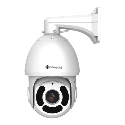
Brahler DIGIMIC PTZ980 User manual

DIGIMIC
PTZ980
Operating Manual
1
BRÄHLER Systems Gm H
Auf der Alten Burg 6
53639 Königswinter
Germany
T +49 (0)2244 930-0
F +49 (0)2244 930-450
sales@ raehler-systems.com
www. raehler-systems.com
07.0920 191011 V1.0 BRÄHLER Systems is committed to continually improving its products and so reserves the right to make technical modifications without notice.
DIGIMIC
PTZ980
3G-SDI Full-HD PTZ Camera
Article no.: 07.0920

DIGIMIC
PTZ980
Operating Manual
2
BRÄHLER Systems Gm H
Auf der Alten Burg 6
53639 Königswinter
Germany
T +49 (0)2244 930-0
F +49 (0)2244 930-450
sales@ raehler-systems.com
www. raehler-systems.com
07.0920 191011 V1.0 BRÄHLER Systems is committed to continually improving its products and so reserves the right to make technical modifications without notice.
Printed in the Federal Repu lic of Germany
If you have any questions a out this operating manual, please contact us:
BRÄHLER Systems Gm H
Auf der Alten Burg 6
53639 Königswinter
T (0)2244 930-0
F (0)2244 930-450
sales@ raehler-systems.com
www. raehler-systems.com
Note: Changes or modifications to this equipment not expressly approved y Brähler Systems could void the
FCC's authority to operate this equipment.
©2019 Brähler Systems Gm H, Königswinter, Germany
All rights reserved, in particular (also in extracts) those of translation, reprint and reproduction y copies or
similar procedures.
Brähler Systems reserves the right to make technical changes without prior notice.

DIGIMIC
PTZ980
Operating Manual
3
BRÄHLER Systems Gm H
Auf der Alten Burg 6
53639 Königswinter
Germany
T +49 (0)2244 930-0
F +49 (0)2244 930-450
sales@ raehler-systems.com
www. raehler-systems.com
07.0920 191011 V1.0 BRÄHLER Systems is committed to continually improving its products and so reserves the right to make technical modifications without notice.
Index
IndexIndex
Index
About this manual .................................................................................................................................................... 5
Symbols ............................................................................................................................................................... 5
General information .............................................................................................................................................. 5
Important notes ........................................................................................................................................................ 6
Safety instructions ................................................................................................................................................ 6
Safety information ................................................................................................................................................ 7
DIGIMIC Camera System ........................................................................................................................................ 8
System components ............................................................................................................................................. 8
Construction ............................................................................................................................................................. 9
Power on initial configuration ................................................................................................................................. 10
Video Output ...................................................................................................................................................... 11
1) Video Output from LAN .............................................................................................................................. 11
2) HDMI Video Output .................................................................................................................................... 11
3) 3G-SDI Video Output ................................................................................................................................. 11
Bracket mount ........................................................................................................................................................ 11
1) Wall mount step ............................................................................................................................................. 11
2. Upside down mount step ............................................................................................................................... 12
Main Features ........................................................................................................................................................ 14
Camera Performance ......................................................................................................................................... 14
Network performance ......................................................................................................................................... 14
Technical Specification .......................................................................................................................................... 15
Interface Instruction ............................................................................................................................................... 17
External Interface ............................................................................................................................................... 17
RS-232 Interface ................................................................................................................................................ 17
Bottom Dial Switch ............................................................................................................................................. 19
Application Instruction ............................................................................................................................................ 20
Video Output ...................................................................................................................................................... 20
Power-On Initial Configuration ....................................................................................................................... 20
Video Output ................................................................................................................................................... 20
Remote Controller .............................................................................................................................................. 21
Applications ........................................................................................................................................................ 22
MENU SETTING ................................................................................................................................................ 26
Main Menu ...................................................................................................................................................... 26

DIGIMIC
PTZ980
Operating Manual
4
BRÄHLER Systems Gm H
Auf der Alten Burg 6
53639 Königswinter
Germany
T +49 (0)2244 930-0
F +49 (0)2244 930-450
sales@ raehler-systems.com
www. raehler-systems.com
07.0920 191011 V1.0 BRÄHLER Systems is committed to continually improving its products and so reserves the right to make technical modifications without notice.
System Setting ............................................................................................................................................... 26
Camera Setting .............................................................................................................................................. 27
EXPOSURE SETTING
................................................................................................................................. 28
COLOR SETTING
......................................................................................................................................... 29
IMAGE
........................................................................................................................................................... 30
FOCUS
.......................................................................................................................................................... 30
NOISE REDUCTION
.................................................................................................................................... 31
P/T/Z ............................................................................................................................................................... 31
Video Format .................................................................................................................................................. 32
Version ........................................................................................................................................................... 32
Restore Default .............................................................................................................................................. 33

DIGIMIC
PTZ980
Operating Manual
5
BRÄHLER Systems Gm H
Auf der Alten Burg 6
53639 Königswinter
Germany
T +49 (0)2244 930-0
F +49 (0)2244 930-450
sales@ raehler-systems.com
www. raehler-systems.com
07.0920 191011 V1.0 BRÄHLER Systems is committed to continually improving its products and so reserves the right to make technical modifications without notice.
A out this manual
A out this manualA out this manual
A out this manual
Keep these operating instructions together with the device. If you pass the device on to a third party, also pass
on this manual.
Sym ols
Sym olsSym ols
Sym ols
The following means of presentation are used in this manual:
Indicates instructions which, if not o served, endanger your health, the functionality of your device or
the safety of your data.
Indicates additional information and tips.
Texts in old and/or underlined are texts or terms that should e highlighted.
General information
General informationGeneral information
General information
Read this manual carefully and attentively. Pay particular attention to information marked with the
a ove sym ols.
All rand names (marked with *) are registered trademarks of their respective owners.
The warranty expires if the device is defective due to improper intervention.
Text
TextText
Text

DIGIMIC
PTZ980
Operating Manual
6
BRÄHLER Systems Gm H
Auf der Alten Burg 6
53639 Königswinter
Germany
T +49 (0)2244 930-0
F +49 (0)2244 930-450
sales@ raehler-systems.com
www. raehler-systems.com
07.0920 191011 V1.0 BRÄHLER Systems is committed to continually improving its products and so reserves the right to make technical modifications without notice.
Important notes
Important notesImportant notes
Important notes
S
SS
Safety instructions
afety instructionsafety instructions
afety instructions
Read this manual!
Keep the manual in a safe place
Note the warnings given
Follow the instructions
Do not use the device near water.
Clean the device only with a dry, clean cloth.
Do not lock the ventilation slot.
Only install the device according to the instructions in this manual.
Do not operate in the vicinity of heat sources such as radiators, stoves or other heat-generating devices
(e.g. amplifiers).
This unit is supplied with an IEC power cord and molded power plug. This is for your safety! Do not
attempt to replace the supplied ca le yourself if it does not fit on your socket. Consult a competent
electrician instead. The electrician can replace the ca le y a ca le that corresponds to the mains
sockets of your country. Or have o solete sockets replaced y new ones.
Protect the power cord from eing crushed or kicked, especially at plugs, sockets, and points where
ca les enter the unit.
Only use accessories and accessories that are suita le according to the manufacturer.
Unplug this equipment during lightning storms or when it is not going to e used for a long time.
Have all maintenance work carried out y qualified personnel. Servicing is required if the apparatus has
een damaged in any way, such as power-supply cord or plug has een damaged, the apparatus has
een dropped, is exposed to moisture, or does not operate normally.
Electric Safety: Installation and operation must accord with electric safety standard
Caution to transport: Avoid stress, vi ration and soakage in transportation, storage and installation.
Polarity of power supply: The power supply of the product is ±12V, the max electrical current is 2A
.Polarity of the power supply drawing.
Careful of installation: Never move the camera y seizing the camera head. Don’t rotate camera head
y hand; otherwise, mechanical trou le will occur. This series item must e put on the smooth desk or
platform, and it cannot e installed slant ways; If the camera is installed on TV or computer, the ase
can e fixed y four dou le-sided adhesive trays. Don’t apply incorrosive liquid, as or solid environment
to avoid the cover which is made up of organic material. To make sure no o stacle in rotation range.
Never power on efore installation is completed.
Don’t disassem le discretionarily: We are not responsi le for any unauthorized modification or
dismantling.
Attention: Electromagnetic field under certain rate may affect camera image!

DIGIMIC
PTZ980
Operating Manual
7
BRÄHLER Systems Gm H
Auf der Alten Burg 6
53639 Königswinter
Germany
T +49 (0)2244 930-0
F +49 (0)2244 930-450
sales@ raehler-systems.com
www. raehler-systems.com
07.0920 191011 V1.0 BRÄHLER Systems is committed to continually improving its products and so reserves the right to make technical modifications without notice.
Safety information
Safety informationSafety information
Safety information
Warning!
Warning!Warning!
Warning!
To reduce the risk of fire or electric shock, do not expose the appliance to rain or moisture. Do not
open the appliance! There are potentially dangerous voltages inside. Refer all servicing to qualified
service personnel.
Watch your step!
Watch your step!Watch your step!
Watch your step!
Use only accessories recommended y the manufacturer to avoid fire, electric shock or other hazards.
Do not remove any parts of the housing to avoid the risk of electric shock. There are no user
servicea le parts. Refer all servicing to qualified service personnel.
D
DD
Disconnection from mains
isconnection from mainsisconnection from mains
isconnection from mains
To disconnect the appliance from the power supply, unplug the appliance from the wall outlet.
Overload!
Overload!Overload!
Overload!
Do not overload your sockets and ca les. This can lead to fire and electric shock.
O jects and liquids
O jects and liquidsO jects and liquids
O jects and liquids
Never insert o jects of any kind into the openings of the unit. This may result in dangerous voltage or short-
circuit parts, resulting in fire or electric shock. Do not spill any liquids on the product. If liquid is spilled on the
product, unplug the product from the wall outlet and have it inspected y a technician.
Maintenance and care
Maintenance and careMaintenance and care
Maintenance and care
There are no user servicea le parts! Do not attempt to repair the unit yourself. Never remove or open covers -
this may expose you to dangerous voltages or other hazards. Leave all maintenance work to qualified
personnel.
Only clean the device with a dry, clean cloth. Do not use detergents or other liquids.
S
SS
Spare parts
pare partspare parts
pare parts
If spare parts ecome necessary, make sure that the technician on site uses spare parts that are approved y
the manufacturer or have the same characteristics as the original parts. The use of unsuita le spare parts may
result in fire, electric shock and other hazards.
Safety Check
Safety CheckSafety Check
Safety Check
After maintenance or repair of the device, a safety check must e carried out to ensure that the device is in a
safe operating condition.
Di
DiDi
Disposal
sposalsposal
sposal
This sym ol on the product, instruction manual or packaging indicates that electrical and electronic
equipment should e disposed of separately from household waste at the end of its useful life. There
is a collection system for recycling within the EU or outside the EU. For further information please
contact the local authorities or the retailer where you purchased the product.
Ensure that used atteries are disposed of in accordance with local regulations. Never throw atteries
into a fire (danger of explosion) and do not dispose of them in the trash can.
If devices are to e scrapped, remove all components such as atteries, housings, printed circuit oards and

DIGIMIC
PTZ980
Operating Manual
8
BRÄHLER Systems Gm H
Auf der Alten Burg 6
53639 Königswinter
Germany
T +49 (0)2244 930-0
F +49 (0)2244 930-450
sales@ raehler-systems.com
www. raehler-systems.com
07.0920 191011 V1.0 BRÄHLER Systems is committed to continually improving its products and so reserves the right to make technical modifications without notice.
ca les. Dispose of all individual components in accordance with local waste disposal regulations.
DIGIMIC
DIGIMIC DIGIMIC
DIGIMIC C
CC
Camera
ameraamera
amera
S
SS
System
ystemystem
ystem
Thank you for choosing the camera system for your DIGIMIC microphone system. You have invested in future-
proof camera and conference technology.
DIGIMIC is an autonomous solution without a PC that configures itself completely automatically. DIGIMIC
meets the requirements of studio technology and thus goes far eyond the actual standard of conference
technology. It goes without saying that the system can e linked to the PC at any time and can thus e
controlled via software. Various functions can e implemented via the TCP/IP interface, such as microphone
control, name management and voting.
The individual microphone units of the CMic series as well as the DDol32 interpreter console are almost self-
explanatory in operation. Delegates and interpreters can thus concentrate on the real thing - the conversation.
In com ination with the software rählerOS or CamControl2, the video switcher MS-SDI16 and the Brähler
PTZ980 cameras, you have always perfectly set the stage for your conference. Up to 16 cameras can e
connected to the Switcher and controlled via the software. Your delegates are thus always taken into the
picture from the est possi le angle.
System
SystemSystem
System
c
cc
component
omponentomponent
omponents
ss
s
Video-Switcher MS-SDI16
DCen32/DCen32 mini
CMic ID/CChair ID
CMic One/CChair One
SMic070 und SMic133
DLine32
DSwitch
DExt
DDol32
CSX4 und DIGIMIC CS
Brähler Microphones (TMD/01; TM58/6)
System accessories (ca les etc.)
Software components such as BrählerOS, CamControl2, DIGIVOTE2, DCen Weaver, etc.
For further information on the individual system components of the DIGIMIC family and their
operation, please refer to the corresponding operating instructions.

DIGIMIC
PTZ980
Operating Manual
9
BRÄHLER Systems Gm H
Auf der Alten Burg 6
53639 Königswinter
Germany
T +49 (0)2244 930-0
F +49 (0)2244 930-450
sales@ raehler-systems.com
www. raehler-systems.com
07.0920 191011 V1.0 BRÄHLER Systems is committed to continually improving its products and so reserves the right to make technical modifications without notice.
Construction
ConstructionConstruction
Construction
Example system image
The camera can e rotated, panned and zoomed. With a com ination of several cameras, almost any angle of a
conference room can e optimally staged.
RS232
Connector
IN and OUT
RS485
connector
Audio
IN
3G
-
SDI
connector
HDMI
connector
Network connector
(RJ45)
Power connector
DC 12V

DIGIMIC
PTZ980
Operating Manual
10
BRÄHLER Systems Gm H
Auf der Alten Burg 6
53639 Königswinter
Germany
T +49 (0)2244 930-0
F +49 (0)2244 930-450
sales@ raehler-systems.com
www. raehler-systems.com
07.0920 191011 V1.0 BRÄHLER Systems is committed to continually improving its products and so reserves the right to make technical modifications without notice.
Connect the video switcher and the desired num er of cameras to a power source. Use only suita le ca les
and plugs. Connect the cameras to the video switcher (IN) using a matching SDI ca le - camera 1 to output 1,
camera 2 to output 2, and so on. Connect the cameras to your computer using the network ca le. Position the
cameras at their destination. If desired, connect (preview) screens to the video switcher (OUT).
If required, the cameras can e adjusted in addition via an external controller. This is useful, when speakers
move away from predefined camera positions. If necessary, connect the external control to your computer via a
network ca le. (For operation of the camera control, please refer to the operating instructions of the
corresponding device.)
The camera system is now ready for use.
Power on initial
Power on initial Power on initial
Power on initial configuration
configurationconfiguration
configuration
1) Power on: Connect DC12V power supply adapter to the power supply socket.
2) Initial configuration: Power on with power indicator light on and remote control receiver light linking, camera
head moves to very left and very ottom position first, then moves to a HOME position (intermediate position
of oth horizontal and vertical). When remote control receiver light stops linking, the self-checking is finished
Note: If you set preset 0, when Power on self-test is completed, the camera automatically moves to the preset
0 position.
Connection main screen
(example)
Power supply
network ca le

DIGIMIC
PTZ980
Operating Manual
11
BRÄHLER Systems Gm H
Auf der Alten Burg 6
53639 Königswinter
Germany
T +49 (0)2244 930-0
F +49 (0)2244 930-450
sales@ raehler-systems.com
www. raehler-systems.com
07.0920 191011 V1.0 BRÄHLER Systems is committed to continually improving its products and so reserves the right to make technical modifications without notice.
Video Output
Video Output Video Output
Video Output
1) Video Output from LAN
1) Video Output from LAN1) Video Output from LAN
1) Video Output from LAN
We page Login: Open your rowser and enter the cameras default IP address 192.168.5.163
192.168.5.163192.168.5.163
192.168.5.163 into the address
ar (factory default). The login page should appear, then enter the user name
admin
and password
admin
(factory default)
Click on the “player is not installed, please download and install!" and follow the installation steps for
installation. Now can carry out PTZ control, preset save and restore, configuration and other operations.
2) HDMI Video
2) HDMI Video2) HDMI Video
2) HDMI Video
Output
OutputOutput
Output
Connect the camera via HDMI video ca le to a suita le HDMI monitor; video output is availa le after camera
self-test.
3)
3)3)
3)
3G
3G3G
3G-
--
-SDI Video Output
SDI Video OutputSDI Video Output
SDI Video Output
Connect the camera via 3G-SDI video ca le to a suita le 3G-SDI monitor; video output is availa le after camera
self-test.
Bracket mount
Bracket mount Bracket mount
Bracket mount
Note: Bracket can only e wall mounted or upside down mounted on template and concrete wall, ut cannot
e installed on plaster oard.
1) Wall mount step
1) Wall mount step1) Wall mount step
1) Wall mount step

DIGIMIC
PTZ980
Operating Manual
12
BRÄHLER Systems Gm H
Auf der Alten Burg 6
53639 Königswinter
Germany
T +49 (0)2244 930-0
F +49 (0)2244 930-450
sales@ raehler-systems.com
www. raehler-systems.com
07.0920 191011 V1.0 BRÄHLER Systems is committed to continually improving its products and so reserves the right to make technical modifications without notice.
2.
2. 2.
2. Upside down mount
Upside down mount Upside down mount
Upside down mount step
stepstep
step

DIGIMIC
PTZ980
Operating Manual
13
BRÄHLER Systems Gm H
Auf der Alten Burg 6
53639 Königswinter
Germany
T +49 (0)2244 930-0
F +49 (0)2244 930-450
sales@ raehler-systems.com
www. raehler-systems.com
07.0920 191011 V1.0 BRÄHLER Systems is committed to continually improving its products and so reserves the right to make technical modifications without notice.

DIGIMIC
PTZ980
Operating Manual
14
BRÄHLER Systems Gm H
Auf der Alten Burg 6
53639 Königswinter
Germany
T +49 (0)2244 930-0
F +49 (0)2244 930-450
sales@ raehler-systems.com
www. raehler-systems.com
07.0920 191011 V1.0 BRÄHLER Systems is committed to continually improving its products and so reserves the right to make technical modifications without notice.
Main Features
Main Features Main Features
Main Features
Camera Performance
Camera Performance Camera Performance
Camera Performance
This series camera offers perfect functions, superior performance and rich interfaces. The features include
advanced ISP processing algorithms to provide vivid images with a strong sense of depth, high resolution and
fantastic color rendition. It supports H.265/H.264 encoding which makes motion video fluent and clear even
with less than ideal andwidth conditions.
1. Super High
Super HighSuper High
Super High-
--
-definition Image:
definition Image:definition Image:
definition Image:
It employs 1/2.8inch high quality CMOS sensor. Resolution is up to
1920x1080 with frame rate up to 60 fps.
2. Various Optical Zoom
Various Optical Zoom Various Optical Zoom
Various Optical Zoom Lenses
LensesLenses
Lenses:
::
:
It has 12X/20X optical zoom lens for options.
3. Leading Auto Focus Technology:
Leading Auto Focus Technology:Leading Auto Focus Technology:
Leading Auto Focus Technology:
Leading auto focus algorithm makes lens a fast, accurate and sta le auto-
focusing.
4. Low Noise and High SNR:
Low Noise and High SNR:Low Noise and High SNR:
Low Noise and High SNR:
Low Noise CMOS effectively ensure high SNR of camera video.
Advanced 2D/3D noise reduction technology is also used to further reduce the noise, while ensuring image
sharpness.
5. Quiet PTZ
Quiet PTZQuiet PTZ
Quiet PTZ: By adopting high accuracy step driving motor mechanism, it works extremely quiet and moves
smoothly and very quickly to a designated position.
6. Multi
MultiMulti
Multi-
--
-Format Video Outputs:
Format Video Outputs:Format Video Outputs:
Format Video Outputs:
support HDMI, 3G-SDI, USB, wired LAN and wireless LAN interfaces. The 3G-
SDI is availa le for 100m transmission at 1080p60 format.
7. Multiple Remote Controls:
Multiple Remote Controls: Multiple Remote Controls:
Multiple Remote Controls: There is IR remoter and 2.4G wireless remote for options. The 2.4G wireless
remote controller will not e affected y angle, distance or IR interference. Support transparent transmission
function.
8. Low
LowLow
Low-
--
-power Sleep Function:
power Sleep Function:power Sleep Function:
power Sleep Function:
Support low-power sleep/wake up, the consumption is lower than 500mW
under sleep mode.
9. Support Multiple Control Protocol:
Support Multiple Control Protocol:Support Multiple Control Protocol:
Support Multiple Control Protocol:
Support VISCA, PELCO-D, PELCO-P protocols which can also e
automatically recognized. Support VISCA control protocol through IP port.
10. RS
RSRS
RS-
--
-232 Cascade Function:
232 Cascade Function:232 Cascade Function:
232 Cascade Function:
ST series support RS-232 cascade function which is convenient for installing.
11. 255 Presets Positions:
255 Presets Positions:255 Presets Positions:
255 Presets Positions:
Up to 255 presets (10 presets y remoter).
12. Wide
WideWide
Wide
Application:
Application:Application:
Application:
Tele-education, Lecture capture, We casting, Video conferencing, Tele-training, Tele-
medicine and Interrogation
Network performance
Network performance Network performance
Network performance
1. Audio Input Interface:
Audio Input Interface:Audio Input Interface:
Audio Input Interface:
Support 16000,32000,44100,48000 sampling frequency and AAC, MP3, PCM audio
coding.
2. Multiple Audio/Video Compression:
Multiple Audio/Video Compression:Multiple Audio/Video Compression:
Multiple Audio/Video Compression:
Support H.264/H.265video compression;AAC,MP3 and PCM audio
compression; Support compression of resolution up to 1920x1080 with frame up to 60 fps and 2 channel
1920x1080p with 30 fps compression.

DIGIMIC
PTZ980
Operating Manual
15
BRÄHLER Systems Gm H
Auf der Alten Burg 6
53639 Königswinter
Germany
T +49 (0)2244 930-0
F +49 (0)2244 930-450
sales@ raehler-systems.com
www. raehler-systems.com
07.0920 191011 V1.0 BRÄHLER Systems is committed to continually improving its products and so reserves the right to make technical modifications without notice.
3. Multiple network protocol:
Multiple network protocol: Multiple network protocol:
Multiple network protocol: Support ONVIF, RTSP, RTMP protocols and RTMP push mode, easy to link
streaming media server (Wowza, FMS)
Technical Specification
Technical SpecificationTechnical Specification
Technical Specification
Model
ModelModel
Model
PTZ980
PTZ980PTZ980
PTZ980
Camera Parameter
Camera ParameterCamera Parameter
Camera Parameter
Sensor 1/2.8 inch high quality HD CMOS sensor
Effective Pixels 16: 9 2.07 megapixel
Video Format 1080P60/50/30/25/59.94/29.97;
1080I60/50/59.94;
720P60/50/30/25/59.94/29.97
Optical Zoom 12X, f=3.9~46.1mm
View Angle 6.3°(tele) 72.5°(wide)
AV F1.8 – F2.4
Digital Zoom 10X
Minimum Illumination 0.5Lux(F1.8, AGC ON)
DNR 2D & 3D DNR
White Balance Auto / Manual/ One
Push/3000K/4000K/5000K/6500K
Focus Auto/Manual
Aperture Auto/Manual
Electronic Shutter Auto/Manual
BLC ON/OFF
WDR OFF/ Dynamic level adjustment
Video adjustment Brightness, Color, Saturation, Contrast,
Sharpness, B/W mode, Gamma curve
SNR >55dB
Input/Output Interface
Input/Output InterfaceInput/Output Interface
Input/Output Interface
Video Interfaces HDMI、3G-SDI、LAN
Image code stream Dou le stream outputs simultaneously
Video Compression format H.264, H.265
Control Signal Interface RS-232 Ring through RS232 output, RS-485
Control Protocol VISCA/Pelco-D/Pelco-P; Baud Rate:
115200/9600/4800/2400 ps
Audio input Interface Dou le track 3.5mm linear input;
AudioCompression Format AAC/MP3/PMC Audio compression
HD IP Interface 100M IP port(100BASE-TX); support IP Visca
control protocol
Network Protocol RTSP/RTMP,ONVIF
Power Interface HEC3800 outlet (DC12V)

DIGIMIC
PTZ980
Operating Manual
16
BRÄHLER Systems Gm H
Auf der Alten Burg 6
53639 Königswinter
Germany
T +49 (0)2244 930-0
F +49 (0)2244 930-450
sales@ raehler-systems.com
www. raehler-systems.com
07.0920 191011 V1.0 BRÄHLER Systems is committed to continually improving its products and so reserves the right to make technical modifications without notice.
PTZ Parameter
PTZ ParameterPTZ Parameter
PTZ Parameter
Pan Rotation ±170°
Tilt Rotation -30°~+90°
Pan Control Speed 0.1 -180°/sec
Tilt Control Speed 0.1-80°/sec
Preset Speed Pan: 60°/sec, Tilt: 30°/sec
Preset Num er 255 presets(10 presets y remote controller)
Other Parameter
Supply Adapter AC110V-AC220V to DC12V/2A
Input Voltage DC12V±10%
Input Current 1A (Max)
Consumption 12W (Max)
Store Temperature -10
℃
to +60
℃
Store Humidity 20% -95%
Working Temperature -10
℃
to +50
℃
Working Humidity 20%--80%
Dimension 150mmx150mmx167.5mm
Weight 1.4kG
Working Environment Indoor
Remote Operation (IP) Remote Upgrade, Re oot and Reset
Accessory Power Supply、RS232 Control Ca le
Optional Accessory Bracket

DIGIMIC
PTZ980
Operating Manual
17
BRÄHLER Systems Gm H
Auf der Alten Burg 6
53639 Königswinter
Germany
T +49 (0)2244 930-0
F +49 (0)2244 930-450
sales@ raehler-systems.com
www. raehler-systems.com
07.0920 191011 V1.0 BRÄHLER Systems is committed to continually improving its products and so reserves the right to make technical modifications without notice.
I
II
Interface Instruction
nterface Instruction nterface Instruction
nterface Instruction
External Interface
External Interface External Interface
External Interface
External interface of PTZ980: RS232 Input/Output, RS485 Input, Audio Input,3G-SDI Output, HDMI Output, LAN, DC12V Power
Interface.
RS
RSRS
RS-
--
-232 Interface
232 Interface232 Interface
232 Interface
232C interface specification as shown elow
Computer or key oard and camera connection
method
Camera WindowsDB-9
1.DTR 1.DCD
2.DSR 2.RXD
3.TXD 3.TXD
4.GND 4.DTR
5.RXD 5.GND
6.GND 6.DSR
7.IR OUT 7.RTS
8.NC 8.CTS
9.RI

DIGIMIC
PTZ980
Operating Manual
18
BRÄHLER Systems Gm H
Auf der Alten Burg 6
53639 Königswinter
Germany
T +49 (0)2244 930-0
F +49 (0)2244 930-450
sales@ raehler-systems.com
www. raehler-systems.com
07.0920 191011 V1.0 BRÄHLER Systems is committed to continually improving its products and so reserves the right to make technical modifications without notice.
RS-232 Mini-DIN 8-pin Port Definition
RS232 (DB9) Port Definition
VISCA networking as shown elow:
The camera has a RS232 input and output interface, so you can cascade as the a ove way.
NO. Port Definition
1 DTR Data Terminal Ready
2 DSR Data Set Ready
3 TXD Transmit Data
4 GND System Ground
5 RXD Receive Data
6 GND System Ground
7 IR OUT IR Commander Signal
8 NC No Connection
NO. Port Definition
1 DCD Data Carrier Detect
2 RXD Receive Data
3 TXD Transmit Data
4 DTR Data Terminal Ready
5 GND SystemGround
6 DSR Data Set Ready
7 RTS Request to Send
8 CTS Clear to Send
9 RI Ring Indicator
Camera cascade connection
method
Camera 1 Camera 2
1.DTR 1.DTR
2.DSR 2.DSR
3.TXD 3.TXD
4.GND 4.GND
5.RXD 5.RXD
6.GND 6.GND
7.IR OUT 7.OPEN
8. NC 8.OPEN

DIGIMIC
PTZ980
Operating Manual
19
BRÄHLER Systems Gm H
Auf der Alten Burg 6
53639 Königswinter
Germany
T +49 (0)2244 930-0
F +49 (0)2244 930-450
sales@ raehler-systems.com
www. raehler-systems.com
07.0920 191011 V1.0 BRÄHLER Systems is committed to continually improving its products and so reserves the right to make technical modifications without notice.
Bottom Dial Switch
Bottom Dial SwitchBottom Dial Switch
Bottom Dial Switch
Dial Switch setting
No.
SW 2
SW 1
Explanation
1
OFF
OFF
Software Upgrade Mode
2
ON
ON
Working Mode

DIGIMIC
PTZ980
Operating Manual
20
BRÄHLER Systems Gm H
Auf der Alten Burg 6
53639 Königswinter
Germany
T +49 (0)2244 930-0
F +49 (0)2244 930-450
sales@ raehler-systems.com
www. raehler-systems.com
07.0920 191011 V1.0 BRÄHLER Systems is committed to continually improving its products and so reserves the right to make technical modifications without notice.
Application Instruction
Application InstructionApplication Instruction
Application Instruction
Video Output
Video Output Video Output
Video Output
Power
PowerPower
Power-
--
-On Initial Configuration
On Initial ConfigurationOn Initial Configuration
On Initial Configuration
Connecting the power, camera will have initial configuration, R indicator light will e flashing. When the camera
return to the HOME position (middle position for P/T), and lens finish zoom in/out, the auto-testing is finished.
IR led will also stop flashing. If the preset 0 is set, camera will rotate to the 0 preset position after initial
configuration.
Video Output
Video Output Video Output
Video Output
Connect to the video output ca le: the user select the output mode according to the machine model.
1) network output: connect this product and your computer through network ca le, then open the rowser,
enter the camera IP address (factory default 192.168.5.163) in the address ar, then to the login page and input
a user name and password (factory default are “admin”) ,Finally enter the preview page, and the image comes
out.
If you forget your user name, password, IP address, you can manually restore the default y the
remote controller key com ination * #
2) 3G-SDI output or HDMI output: Connect the monitor with the corresponding video output interface, then the
monitor output image.
This manual suits for next models
1
Table of contents
