Leviton VSOUT User manual

DESCRIPTION
The Leviton Outdoor video monitoring camera uses a single Cat 5e cable to distribute both power and video between the camera and Leviton Structured Media™ Center.
INSTALLATION
Install with a single gang exterior water-proof junction box for new construction and retrofit installations at each of the camera locations. Some installations may require a
water-proof surface mount box if installing to an exterior wall, trim, or soffet. NOTE: When installed in indoor applications, use a low voltage mounting ring.
WIRING
To prewire for the Outdoor Camera, simply run a single Cat 5e UTP cable from the SMC to each camera location desired.
NOTE: If your cable run length exceeds 100 meters (328 ft) you will need to
power your camera locally. Install a two conductor (minimum 18-2) cable with
your Cat 5e to locally power the camera. Also, see "Powering Locally" in the
POWERING YOUR CAMERA section.
INSTALLING THE OUTDOOR CAMERA:
•Strip back your Cat 5e cable and terminate to camera using one of the
following methods:
a)
Terminate the camera Cat 5e cable directly onto the camera board
using the 110 IDC termination block provided. Fan out your Cat 5e
cable and follow the color code indicated in Figure 2. Punch down your
Cat 5e cable using a 110 punch tool.
b)
Terminate a Cat 5e jack 5G108-R*5 (sold separately) to your cable
(use T568A color codes - Figure 3), then use a short Cat 5e patch
cord from the jack to the RJ-45 on the camera board to complete the
connection (Figure 4).
•Set Dip Switch to termination method used (Figure 1):
a) IDC (Leviton recommended) b) RJ-45
c) LOCAL
NOTE: Local is used if you are powering your camera locally
(refer to Powering Locally).
•Mount the camera onto the box securing the mounting plate with
gasket to the gang box (if mounting in harsh weather exposed to
wind and rain take caution to ensure the camera is sealed water tight into the box).
NOTE: If mounting the outdoor camera to a wall use the threaded mounting hole on
the bottom of the camera back side. If mounting camera to a ceiling or a soffet, simply
rotate the camera on the ball and socket joint to avoid an inverted image. Alternatively, in
extreme situations, use the threaded mounting hole on the top, back side of the camera.
•To adjust the camera viewing angle loosen twist knob on the mounting bracket, adjust
the camera angle and tighten the twist knob.
POWERING YOUR CAMERA:
Powering Remotely with Camera Hub (Cat. No. VSHUB):
If your camera Cat 5e cable is 100 Meters (328ft) or less, your camera can be
powered over the Cat 5e from the Camera Hub located inside your Structured
Media System. A power jack on the Camera Hub requires 12VDC power from
either the power supply provided with the Camera Hub board or one of the power
supplies listed below:
Leviton Compatible Power Supplies:
NOTE: Each Outdoor Camera in no light conditions draws about 220 mA from the
Camera Hub. Each Indoor Camera draws about 110 mA from the Camera Hub.
Make sure the sum of the currents from all devices powered by the
power supply in the SMC does not exceed the maximum output of
that power supply.
• 47605-PSA (Maximum output: 12V DC at 3000 mA)
• 47605-PSB (Maximum output: 12V DC at 750 mA)
• 48212-DC (Maximum output: 12V DC at 1500 mA)
Outdoor Camera
Installation Instructions
DI-000-VSOUT-00A VSOUT
59-25 Little Neck Parkway.
Little Neck, N.Y. 11362-2591, USA
Tech Support: 800-824-3005
www.leviton.com
Figure 4
LED
BL OR BRGR
Cat # VSIND/VSOUT
Assembled in Mexico
www.leviton.com
RCA
IDC
local
RJ45
Camera Board
RJ45 Jack
inserts here
Cat 5e
Patch Cord
Cat 5e Jack
5G108-R*5
(to Voice and Data Board)
Twist knob
Package Contents:
Camera Unit (1)
Power Supply AC Adapter (1)
Power Adapter (1) with screws
LED
BL OR BRGR
IN
OUT
Cat # VSIND/VSOUT
Assembled in Mexico
www.leviton.com
RCA
local
RJ-45
IDC
RJ45
Power/Video
LED
BL OR BRGR
IN
OUT
Cat # VSIND/VSOUT
Assembled in Mexico
www.leviton.com
RCA
IDC
local
RJ45
IDC
Power/Video
LED
BL OR BRGR
IN
OUT
Cat # VSIND/VSOUT
Assembled in Mexico
www.leviton.com
RCA
local
RJ45
IDC
Local Power
Video over
IDC/RJ45
RJ45 jack
inserts here
a) b)
*
Recommended for Outdoor Camera
c)
Figure 1 – Dip Switch Settings
White/Blue 5
White/Orange 3
Green 2
PIN #
White/Green 1
PIN #
6 Orange
4 Blue
7 White/Brown
8 Brown
Figure 3
White/Green
Green
White/Orange
Orange
Blue
White/Blue
White/Brown
Brown
Figure 2

NOTE: The Camera Hub board regulates and raises the voltage of the 12VDC input to 15VDC before sending it
over the Cat 5e to the camera. Power is sent over 3 pairs of Cat 5e conductors to reduce the resistance loss in
the cable. A regulator circuit at the camera reduces the voltage back to 12VDC to power the camera engine.
One pair of the Cat 5e is a balanced video signal from the camera to the SMC Camera Hub.
IMPORTANT INSTRUCTIONS
1. Read and understand all instructions. Follow all warnings and instructions marked on the product.
2. Do not use this product near water—e.g., near a tub, wash basin, kitchen sink or laundry tub, in a wet basement,
or near a swimming pool.
3. Never push objects of any kind into this product through openings, as they may touch dangerous voltages.
4. SAVE THESE INSTRUCTIONS.
SAFETY INFORMATION
1. Never install communications wiring or components during a lightning storm.
2. Never install communications components in wet locations unless the components are designed specifically for
use in wet locations.
3. Never touch uninsulated wires or terminals unless the wiring has been disconnected at the network interface.
4. Use caution when installing or modifying communications wiring or components.
5. To prevent electrical shock, each opening must be filled with a module.
LIMITED 2 YEAR WARRANTY AND EXCLUSIONS
Leviton warrants to the original consumer purchaser and not for the benefit of anyone else that this product at
the time of its sale by Leviton is free of defects in materials and workmanship under normal and proper use for
two years from the purchase date. Leviton’s only obligation is to correct such defects by repair or replacement,
at its option, if within such two year period the product is returned prepaid, with proof of purchase date, and
a description of the problem to Leviton Manufacturing Co., Inc., Att: Quality Assurance Department, 59-25
Little Neck Parkway, Little Neck, New York 11362-2591. This warranty excludes and there is disclaimed liability
for labor for removal of this product or reinstallation. This warranty is void if this product is installed improperly
or in an improper environment, overloaded, misused, opened, abused, or altered in any manner, or is not used
under normal operating conditions or not in accordance with any labels or instructions. There are no other or
implied warranties of any kind, including merchantability and fitness for a particular purpose, but if any
implied warranty is required by the applicable jurisdiction, the duration of any such implied warranty, including
merchantability and fitness for a particular purpose, is limited to two years. Leviton is not liable for incidental,
indirect, special, or consequential damages, including without limitation, damage to, or loss of use of,
any equipment, lost sales or profits or delay or failure to perform this warranty obligation. The remedies
provided herein are the exclusive remedies under this warranty, whether based on contract, tort or otherwise.
For Technical Assistance Call:
1-800-824-3005 (U.S.A. Only)
www.leviton.com
DI-000-VSOUT-00A
TROUBLESHOOTING:
No Video from camera RCA?
• Ensure camera board and Camera Hub board are powered Green LED should be lit on each board.
• Plug RCA cable into monitor and set to composite video signal.
No Video at Camera Hub board?
• Verify all RJ-45 plugs are wired T568-A
Signal Connections (T568A)
Wire Color
White/Green
Green
White/Orange
Blue
White/Blue
Orange
White/Brown
Brown
Signal
Power
Ground
Video Signal
Ground
Power
Video Signal Ground (-)
Power
Ground
Powering Locally
If your camera Cat 5e cable length exceeds 100 Meters you must use the 2-pin plugglabe connector located on
the camera board and power the camera from a local power source. Use the 120VAC to 15VDC power supply
included with the camera. Power is sent over 3 pairs of Cat 5e conductors to send 15VDC power supplying the
camera circuits. One pair of the Cat 5e is a balanced video signal from the camera to the Camera Hub board.
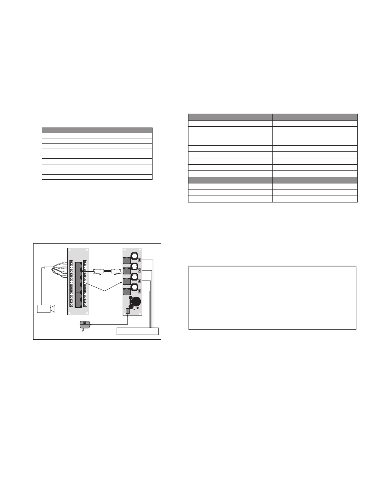
CONNECTING YOUR CAT 5E CAMERA CABLE IN THE SMC (Figure 5):
•Snap the Camera Hub (Cat. No. VSHUB) into the plastic mounting bracket
(Cat. No. 47612-SBK) and mount assembly into the SMC.
•Terminate the Cat 5e Camera cable in the SMC to an open port on a Leviton Voice and Data board (Cat. No.
47605-C5 - sold separately).
•Next connect a Cat 5e patch cable from the Voice and Data board to one of the 4 ports on the Camera Hub board
(Cat. No. VSHUB).
NOTE: Leviton recommends terminating Cat 5e camera cables to the 110 IDC block on a Voice and Data Board for
long term reliability and to avoid wiring mistakes (Figure 2).
IN
OUT
IN
OUT
IN
OUT
IN
OUT
To Modulator, Sequencer,
IP Quad or direct to TV monitor
Cat 5e
Patch Cord
Camera Hub
Voice and Data
Module
47605-C5
Power Jack
Center Conductor
is +12 VDC
Note: All UTP
Terminations
based on T568A
Composite
RCA
Cable to
device
Indoor Camera or
Outdoor Camera
Figure 5
Camera Parameter Value
Pick up device 1/3” CCD
Picture Elements H*V NTSC 510*492
Camera Resolution >420 lines
Lens 4.3 mm
Sensitivity 0 Lux (Auto IR Illumination to 30+ ft)
S/N Ratio > 48 dB (AGC off)
White Balance Auto
Video Out 1Vpp, 75 Ohm
Auto Gain control Auto
Camera Assembly Power Requirements Value
Input Voltage +15V DC +/- 10% max
Current Consumption 220 mA +/- 10% max
Power Consumption <3.3W max.
CAMERA SPECIFICATIONS:

FOLD SCHEME
8.5"
11"
4.25"
5.5"
FINAL
Fold Line
DOCUMENTATION
LEVITON INSTRUCTION SHEET/MANUAL
SPECIFICATIONS
HSZ 11/01/06
Helvetica
DI-000-VSOUT-00A
Black
N/A
Final fold size:
50 Lb. offset
5.5" X 4.25"
Overall size:
11" X 8.5"
Paper size:
Cat No.
Cat No.
Cat No.
Other Leviton Security Camera manuals