Brahms PVR01 User manual
PREVENTION
THEFT
FIRE
GAS
BPT Spa
Centro direzionale e Sede legale
Via Cornia, 1/b
33079 Sesto al Reghena (PN) - Italia
http://www.bpt.it
mailto:[email protected]t
PVR01_EN 24838300 22-02-10.doc
Page 1 of 24
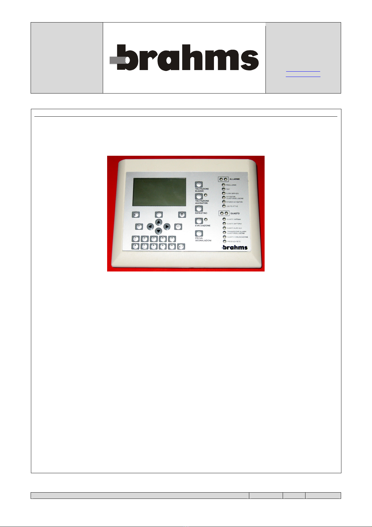
PVR01
Remote panel for control units ACPxx

PVR01_EN 24838300 22-02-10.doc
Page 2 of 24
CONTENTS
PVR01..........................................................................................................................................................................................1
Remote panel for control units ACPxx......................................................................................................................................1
CONTENTS ................................................................................................................................................................................2
INTRODUCTION ......................................................................................................................................................................3
TECHNICAL CHARACTERISTICS .......................................................................................................................................4
ELECTRICAL CHARACTERISTICS .................................................................................................................................4
MECHANICAL CHARACTERISTICS ...............................................................................................................................4
CLIMATIC CHARACTERISTICS.......................................................................................................................................4
DESCRIPTION OF THE PANEL .............................................................................................................................................5
NAVIGATION CONTROLS ................................................................................................................................................5
KEYS FOR DATA INSERTION ..........................................................................................................................................6
CONTROLS............................................................................................................................................................................7
SIGNALLING LED'S ............................................................................................................................................................8
CONNECTIONS.........................................................................................................................................................................9
EXAMPLE OF CONNECTION TO AN ACPXX CONTROL UNIT ...............................................................................9
EXAMPLES OF USE...............................................................................................................................................................10
EXAMPLE NO. 1.................................................................................................................................................................10
EXAMPLE NO. 2.................................................................................................................................................................11
EXAMPLE NO. 3.................................................................................................................................................................12
EXAMPLE NO. 4.................................................................................................................................................................13
OPERATIONS ..........................................................................................................................................................................14
SCREEN AT REST ..............................................................................................................................................................14
MAIN MENU .......................................................................................................................................................................14
1. OPERATOR..........................................................................................................................................................................15
1.1. SETTING OF DATE AND TIME ...............................................................................................................................15
1.2. DISPLAY OF VERSIONS OF SOFTWARE/HARDWARE ....................................................................................15
2. MAINTENANCE .................................................................................................................................................................16
3. INSTALLATION .................................................................................................................................................................17
3.1. CONTROLLED CONTROL UNITS...........................................................................................................................17
3.1.1. Install.......................................................................................................................................................................17
3.1.2. Set Filter..................................................................................................................................................................18
3.1.3. Remove ...................................................................................................................................................................19
3.2. EVENTS ........................................................................................................................................................................20
3.2.1. Display list ..............................................................................................................................................................20
3.2.2. Print .........................................................................................................................................................................20
3.2.3. Delete ......................................................................................................................................................................21
3.2.4. Reset Chronology ...................................................................................................................................................21
3.2.5. Settings....................................................................................................................................................................21
3.3. SETTINGS.....................................................................................................................................................................22
3.4. LOCAL NET .................................................................................................................................................................23
3.4.1. Parameter Setting....................................................................................................................................................23
3.4.2. View Devices..........................................................................................................................................................24

PVR01_EN 24838300 22-02-10.doc
Page 3 of 24
INTRODUCTION
The PVR01 is a remote control panel that can be associated with the ACPxx fire detection control units and it is used to
show the information of:
•Fire alarm
•Fire pre-alarm
•Test
•Fault
•Out of service
The panels can be singularly programmed as passive (display only) or active (also command). From each panel it is
possible to perform all of the operations that can be performed from the control unit, except programming. Each panel
can be assigned a certain number of control units (max. 16) and the type of events to supervise for each of them. Each
panel memorizes a total of up to 1000 events. Each panel may be assigned the type of events to be printed using the
RS232 serial port.
The PVR01 is a compact container that can be wall-mounted or placed on the table. The power supply can be drawn
directly from the control unit (for example on OUT1 which provides direct supply of 24V DC). If the energy balance of
the latter does not allow it, it is necessary to use an external power supplier.
The panel includes the following elements:
•An LCD viewer with eight lines of twenty-one characters each.
•A series of LED's for indications.
•A membrane keypad.
•A serial port
N.B.: For the operating of logic of fire prevention systems created with ACPxx control units and related sensors,
refer to the manuals for the control unit.

PVR01_EN 24838300 22-02-10.doc
Page 4 of 24
TECHNICAL CHARACTERISTICS
ELECTRICAL CHARACTERISTICS
The PVR01 panel is designed to be powered directly by the ACPxx control unit or by an external power supplier.
•Power supply: 24 V DC
•Current input: 50 mA
MECHANICAL CHARACTERISTICS
Weight: 450 g
Dimensions: L x H x D = 200 x 155 x 65 mm
Protection rating: IP30
CLIMATIC CHARACTERISTICS
Operating temperature: -10 °C ... +50 °C
Admissible temperature during operation: 93% without condensation
Storage temperature: +10 °C ... +50 °C
Admissible temperature during storage: 85% without condensation
PVR01_EN 24838300 22-02-10.doc
Page 5 of 24
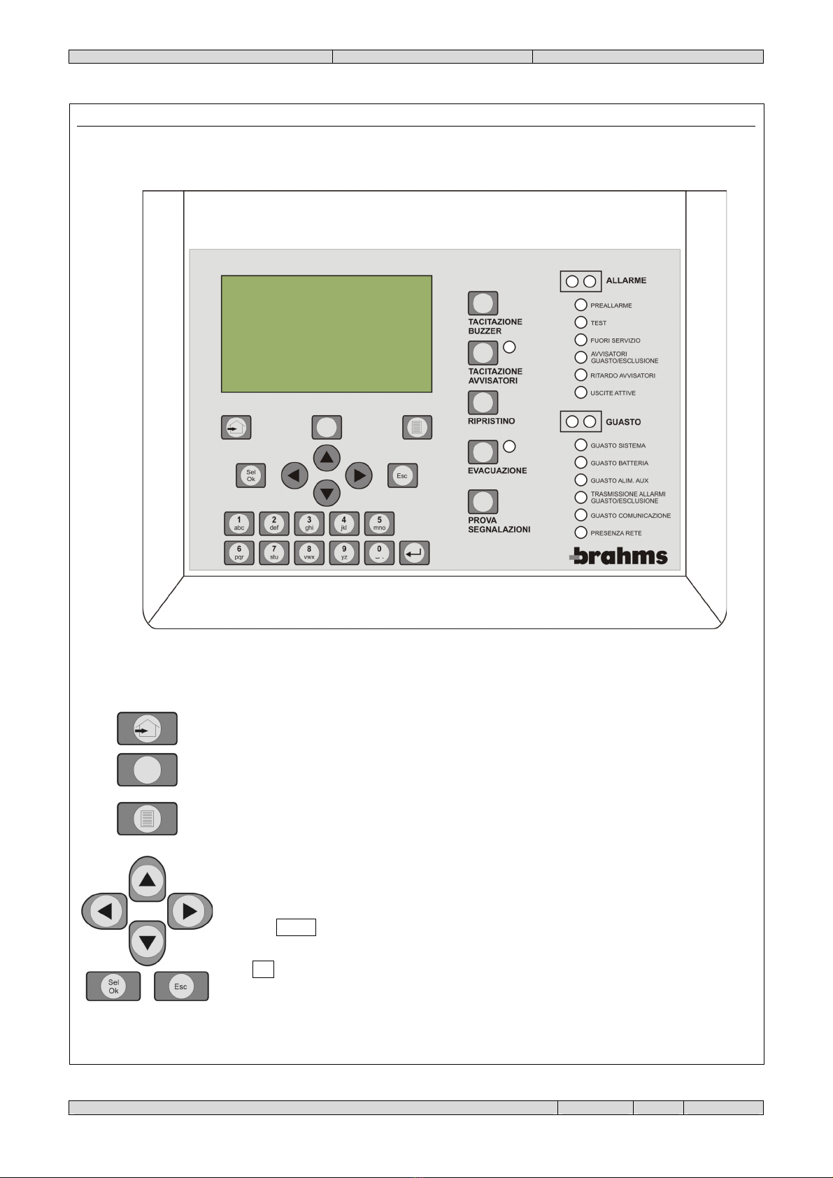
DESCRIPTION OF THE PANEL
NAVIGATION CONTROLS
"Go to main menu" key: use this key to access the main menu.
Function key: this key is generally inactive, its function, variable, is specified by a message
that appears at the key at the bottom of the page.
"Display active events" key: if the display shows alarm or fault messages (priority), by
pressing this key it is possible to view all other active events. An asterisk at the bottom of the
display at the key means that there are other active events that can be displayed.
The arrow keys can be used to move among the various items of the operating menus, or
among the various fields of the display windows, or among the various characters of the same
alphanumeric string.
The key Sel/Ok is used to access the menu item selected with the arrow keys, or to confirm
insertion of data in fields with variable values.
The Esc key is used to exit the current operating function and return to the next highest
hierarchical level or to abort an operation or to delete the insertion of values.

PVR01_EN 24838300 22-02-10.doc
Page 6 of 24
KEYS FOR DATA INSERTION
The alphanumeric keypad is used to insert numerical data such as passwords, addresses, and
so forth. If it is used to insert names, it is possible to insert capital letters, small letters or
numerals. The selection of the different modes is made using the function key as shown on
the display.
Characters are inserted consecutively by pressing the key for the character several times until
it is shown. If the character to be inserted is included on the same key of the last one inserted,
wait for the cursor to move to the next space.
The Enter key makes it possible to modify a variable field indicated by a small flashing
triangle, which is normally steady.

PVR01_EN 24838300 22-02-10.doc
Page 7 of 24
CONTROLS
Buzzer
Mute:
Use this control if you want to silence the acoustic signal in the event of fault (intermittent
sound), or alarm (continuous sound).
Silence
sounder
Use this control to silence all the alarm sounders connected to the control unit. Silencing the
sounders does not reset the alarm. The LED located alongside the key will come on in the
presence of silenced alarms. If you want to re-activate the sounders before resolving the
cause for their activation, just press the key again.
If there is a second alarm or failure with the sounders silenced, the sound signal will resume.
The silencing of the outputs (and their possible reactivation) towards fire alarm devices, in
compliance with EN 54-2, is an operation with access level of 2. Therefore, after pressing the
relative button, it is necessary to insert the level 2 password (default = 22222) using the
alphanumeric keypad; then confirm with the key Sel/Ok.
Alarm reset
Use this control to reset the fire alarm or failure conditions once their causes have been
identified and removed. The reset causes the deactivation of the failure and/or alarm outputs
and the cessation of the corresponding acoustic and luminous signals.
In compliance with EN 54-2, resetting is an operation with an access level of 2 it is therefore,
after pressing the relative button, it is necessary to insert the level 2 password (default =
22222) using the alphanumeric keypad; then confirm with the key Sel/Ok.
Evacuation
Use this key to start the evacuation procedure which will immediately activate the output
towards the fire alarm devices.
The LED located alongside the key will start flashing.
To interrupt the signalling procedure, press the Evacuation key again.
In compliance with EN 54-2, starting the evacuation procedure (and its possible interruption)
is an operation with an access level of 2. Therefore, after pressing the relative button, it is
necessary to insert the level 2 password (default = 22222) using the alphanumeric keypad;
then confirm with the key Sel/Ok.
Lamp test
Press this key to turn on all the LED's of the front panel and all of the pixels
of the display to check proper operation.
PVR01_EN 24838300 22-02-10.doc
Page 8 of 24
SIGNALLING LED'S
Alarm
2
LED's
red
Fire alarm signal. Activated upon occurrence of the cause that has set off the
alarm. Deactivated when alarm condition is reset.
Pre-alarm
LED
red
Fire pre-alarm signal. Activates upon occurrence of a cause of alarm for a
zone defined as "double permission". It is deactivated upon reset of the alarm
condition.
Test
LED
yellow
Signalling of a zone test status. This is activated when any zone is placed in
test status and is deactivated if all of the zones are not in this status.
Out of service
LED
yellow
Signal for point/zone/output out of service. This is activated when any element
of the system is taken out of service for maintenance, it is inactive if all the
elements are activated.
Sounder
fault/disabled
LED
yellow
This signal flashes when a failure has been detected in the output for the
control of the alarm devices OUT2 SOUNDER; it is steady when the same
output has been placed out of service by the dedicated software.
Sounder delayed
LED
yellow
This signal is active when the output for the control of the alarm devices has
been delayed using the dedicated software option. It is inactive when this
output is immediate.
Output active
LED
yellow
This signal is active when one or more outputs are active.
The list of active outputs can be seen by pressing the key
Display of active events starting from the initial window.
Fault
2
LED's
yellow
Failure signal. Flashes upon occurrence of the cause of the failure.
Deactivated when failure condition is reset. This signal is also active in the
presence of any of the specific failure signals as described hereunder.
System fault
LED
yellow
Signal of system failure. Flashing. This status is caused by a serious error in
the running of a software programmed that prevents proper operation of the
system. The ACPxx control unit can be reset only by pressing the key RESET
SYSTEM FAULT located on the card at top centre as indicated in the manual
of the control unit.
Battery fault
LED
yellow
Fault signal on charge circuit of the batteries of the control unit. Flashing.
Check the correctness of the battery connection, the status of the protection
fuse of the circuit and the status of the batteries.
Aux Power Supp.
Fault
LED
yellow
Signals a failure in the battery recharging circuit. Flashing.
Fire routing
fault/disabled
LED
yellow
This signal flashes when a fault has been detected on the output for the
transmission of the alarm signal OUT4 FIRE R.; it is steady when the output
has been placed out of service by the dedicated software option.
Communications
Fault
LED
yellow
This signal flashes when a fault occurs in the RS485 communications network.
Check the status of connections and network settings.
Main power
supply on
LED
green
This signal is on steady when power is supplied to the PVR01 panel.
PVR01_EN 24838300 22-02-10.doc
Page 9 of 24
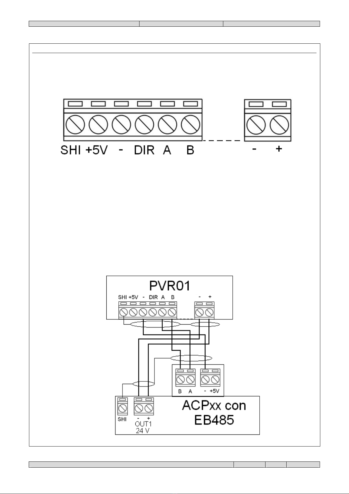
CONNECTIONS
Remove the panel to access the internal terminals.
SHI = Connect the shielding of the connection cables.
+ 5V = Not used.
- = Connect to the “-“ of the other devices of the network.
DIR = Not used.
A= Connect to the terminal "A" of the other network devices.
B= Connect to the terminal "B" of the other network devices.
-= Connect to the power supply negative.
+= Connect to the positive + 24 V DC of the power supply.
EXAMPLE OF CONNECTION TO AN ACPXX CONTROL UNIT

PVR01_EN 24838300 22-02-10.doc
Page 10 of 24
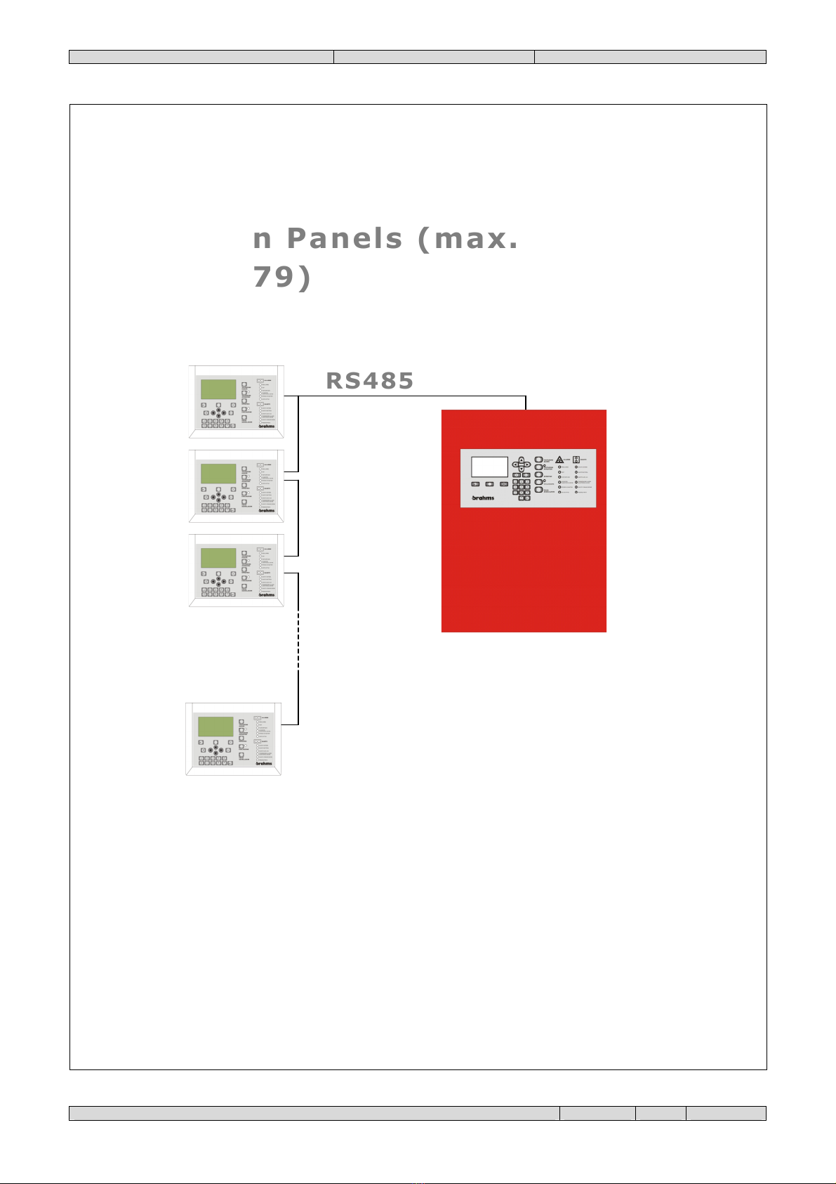
EXAMPLES OF USE
The ACPxx control units and the PVR01 panels allow good flexibility in the creation of fire prevention systems. As
shown in the examples that follow, it is possible to use the panels in various kind of systems.
EXAMPLE NO. 1
RS485
RS485
RS485
RS485
1 Panel
1 Panel
1 Control Unit
1 Control Unit
PVR01_EN 24838300 22-02-10.doc
Page 11 of 24
EXAMPLE NO. 2
RS485
RS485
.
.
.
.
.
n Panels (max.
n Panels (max.
79)
79)
1 Control Unit
1 Control Unit

PVR01_EN 24838300 22-02-10.doc
Page 12 of 24
EXAMPLE NO. 3
RS485
RS485
1 Panel
1 Panel
n Control Units (max
n Control Units (max
16)
16)
PVR01_EN 24838300 22-02-10.doc
Page 13 of 24
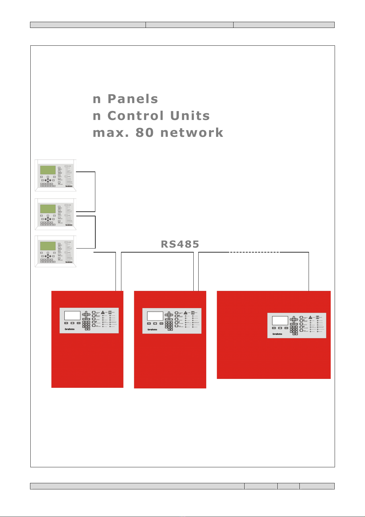
EXAMPLE NO. 4
RS485
RS485
n Panels
n Panels
n Control Units
n Control Units
max. 80 network
max. 80 network
devices
devices

PVR01_EN 24838300 22-02-10.doc
Page 14 of 24
OPERATIONS
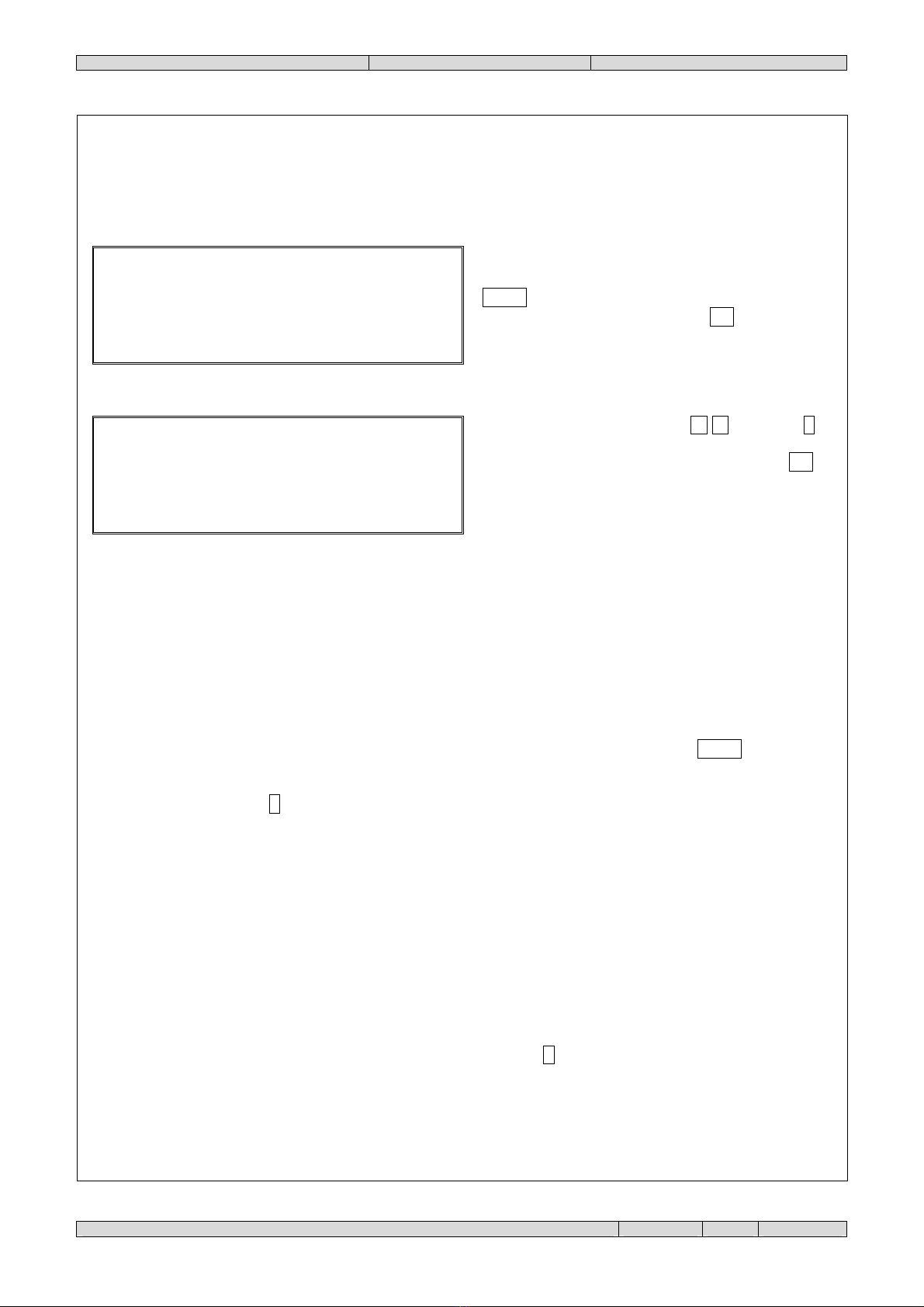
SCREEN AT REST
Once the panel is powered, the initial window will be shown.
MAIN MENU
To recall the main menu, press the key . The display will show:
Select the function with the keys /, and then
confirm the selection with the key Sel/Ok or type in
directly the number that appears to the left of the item.
To exit a function and return to the next highest level of
the tree menu, press the key Esc.
There are three main options:
1. OPERATOR
This menu makes it possible to set the date and time and to display the SW and HW versions of the panel.
2. MAINTENANCE
This menu makes it possible to view the data on the control units that are controlled.
3. INSTALLATION
This menu lets you set the connection to the network and manage the control units that are to be controlled.
<
data
>
<
ora
>
B
R
A
H
M
S
E
L
E
T
T
R
O
N
I
C
A
P
A
N
N
E
L
L
O
x
x
x
x
x
x
x
P
R
O
M
P
T
M
O
D
I
F
I
C
A
B
I
L
E
M
e
n
u
P
r
i
n
c
i
p
a
l
e
1
-
O
P
E
R
A
T
O
R
E
2
-
M
A
N
U
T
E
N
Z
I
O
N
E
3
-
I
N
S
T
A
L
L
A
Z
I
O
N
E

PVR01_EN 24838300 22-02-10.doc
Page 15 of 24
M
e
n
u
o
p
e
r
a
t
o
r
e
1
-
I
M
P
O
S
T
A
Z
.
D
A
T
A
-
O
R
A
2
-
V
E
R
S
I
O
N
I
I
M
P
O
S
T
A
Z
.
D
A
T
A
-
O
R
A
D
A
T
A
C
O
R
R.
:
x
x
/
x
x
/
x
x
O
R
A
C
O
R
R
:
x
x
/
x
x
/
x
x
C
A
L
I
B
.
R
T
C
:
x
x
x
V
E
R
S
I
O
N
I
S
W
/
H
W
V
E
R
S
.
S
W
µ
C
:
x
.
x
x
V
E
R
.
H
W
:
x
.
x
x
N
.
S
E
R
I
E
:
x
x
x
-
x
x
x
x
x
1. OPERATOR
Once this menu is selected, the display will show:
Select the function with the keys /, and then
confirm the selection with the key Sel/Ok, or typing in
directly the number that appears to the left of the item.
To exit a function and return to the next highest level of
the tree menu, press the key Esc.
1.1. SETTING OF DATE AND TIME
Select the value to be modified with the keys /,
then press and type in the correct data. Finally, press
Sel/Ok to confirm. To exit a function and return to the
next highest level of the tree menu, press the key Esc.
1.2. DISPLAY OF VERSIONS OF SOFTWARE/HARDWARE
To exit the function press the key Esc.
PVR01_EN 24838300 22-02-10.doc
Page 16 of 24
M
e
n
u
m
a
n
u
t
e
n
z
i
o
n
e
1
-
V
I
S
U
A
L
I
Z
Z
A
Z
I
O
N
E
V
I
S
U
A
L
I
Z
Z
A
Z
I
O
N
E
1
-
C
E
N
T
R
.
C
O
N
T
R
O
L
L
.
S
E
L
E
Z
.
I
N
D
.
C
E
N
T
R
A
L
E
I
N
D
I
R
I
Z
Z
O
:
x
x
I
N
F
O
R
M
A
Z
I
O
N
I
C
E
N
T
R
A
L
E
I
N
D
.
:
x
x
N
.
:
C
E
N
T
R
A
L
E
0
2
F
.
E
V
.
:
x
x
x
x
x
x
x
x
x
x
x
x
x
x
F
I
L
T
R
O
Z
O
N
E
:
x
x
x
x
x
x
x
C
O
N
T
R
O
L
L
O
R
E
M
O
T
O
:
x
x
C
O
M
U
N
I
C
A
Z
.
O
K
:
x
x
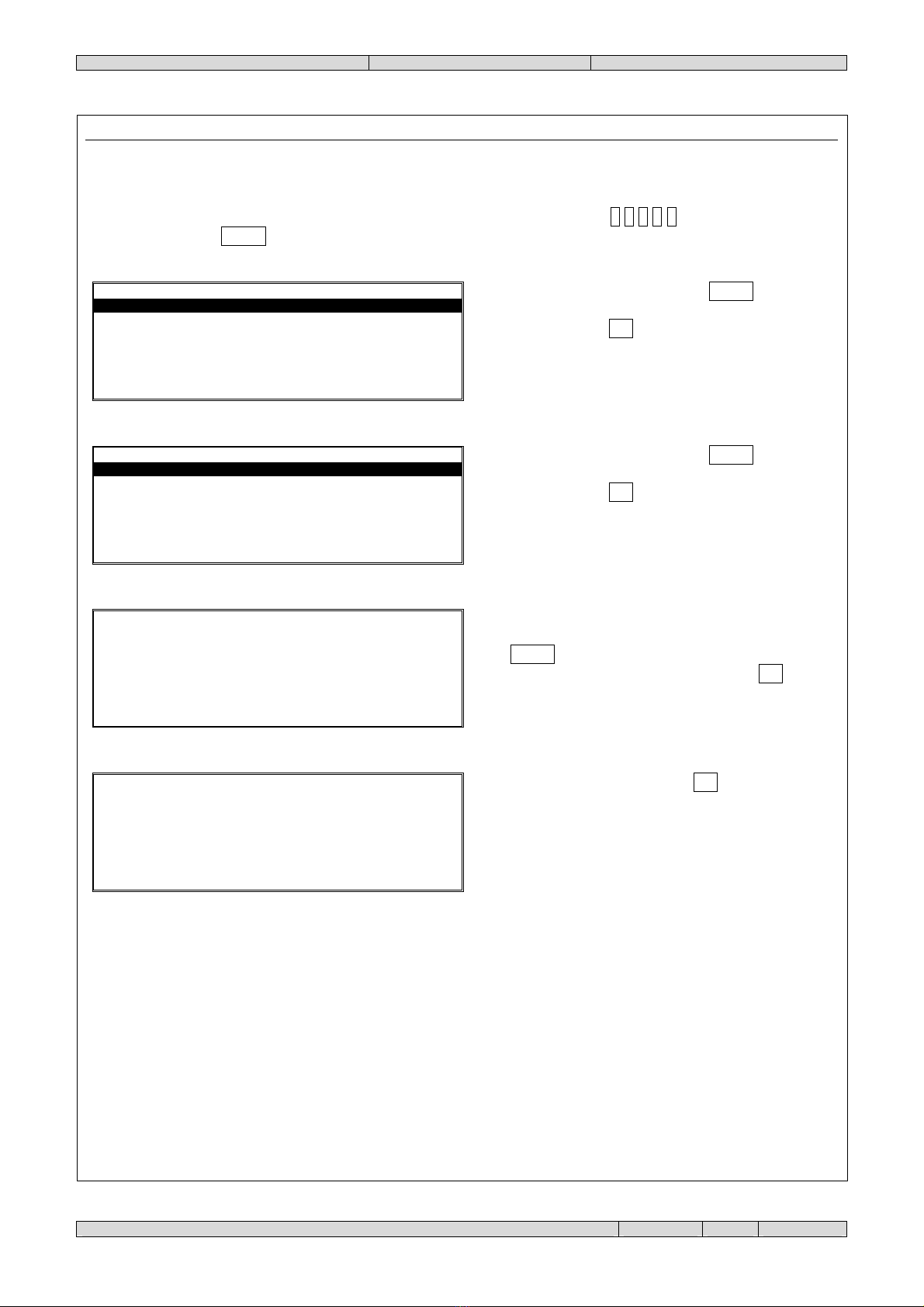
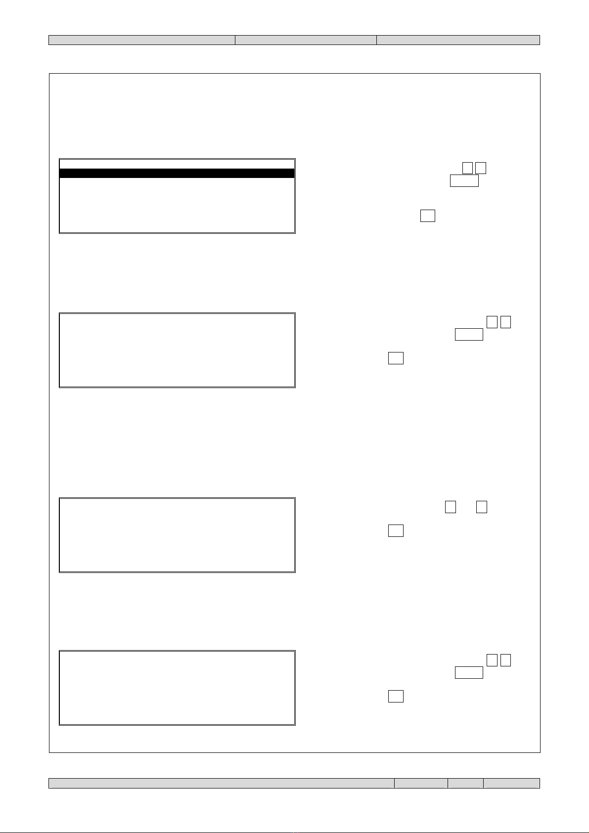
2. MAINTENANCE
Once this menu is selected, the level 2 password will be requested. The default is 2 2 2 2 2 . Insert the numbers and
confirm with the key Sel/Ok, the display will show:
Confirm the choice with the key Sel/Ok . To exit a
function and return to the next highest level of the tree
menu, press the key Esc.
Confirm the choice with the key Sel/Ok . To exit a
function and return to the next highest level of the tree
menu, press the key Esc.
Insert the number of the control unit for which to view
the information and then confirm the selection with the
key Sel/Ok . To exit a function and return to the next
highest level of the tree menu, press the key Esc.
To exit the function press the key Esc.
The following information is obtained:
•ADD.: (control unit address)
•N.: (name of control unit)
•F. EV.: (filter of events managed by panel)
•ZONE FILTER: (zone filter managed by the panel)
•REMOTE CONTROL: (control of the control unit by the panel)
•COMMUNICAT. OK: (communications status)
PVR01_EN 24838300 22-02-10.doc
Page 17 of 24
M
e
n
u
i
n
s
t
a
l
l
a
z
i
o
n
e
1
-
C
E
N
T
R
.
C
O
N
T
R
O
L
L
.
2
-
E
V
E
N
T
I
3
-
I
M
P
O
S
T
A
Z
I
O
N
I
4
-
R
E
T
E
L
O
C
A
L
E
M
E
N
U
C
E
N
T
R
A
L
I
C
O
N
T
R
.
1
-
I
N
S
T
A
L
L
A
2
-
I
M
P
O
S
T
A
F
I
L
T
R
O
3
-
R
I
M
U
O
V
I
S
E
L
E
Z
.
I
N
D
.
C
E
N
T
R
A
L
E
I
N
D
I
R
I
Z
Z
O
:
x
x
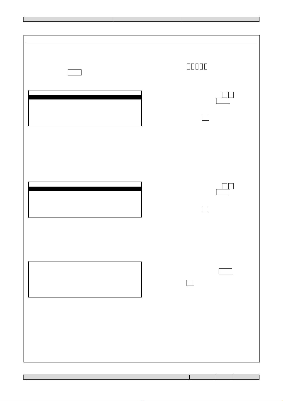
3. INSTALLATION
Once this menu is selected, the level 3 password will be requested. The default is 3 3 3 3 3 . Insert the numbers and
confirm with the key Sel/Ok, the diplay will show:
Select the function with the keys /, and then
confirm the selection with the key Sel/Ok, or typing in
directly the number that appears to the left of the item.
To exit a function and return to the next highest level of
the tree menu, press the key Esc.
3.1. CONTROLLED CONTROL UNITS
The panel can control up to 16 control units.
Select the function with the keys /, and then
confirm the selection with the key Sel/Ok, or typing in
directly the number that appears to the left of the item.
To exit a function and return to the next highest level of
the tree menu, press the key Esc.
3.1.1. Install
If you want to add a control unit to those managed by the panel, proceed as follows.
Insert the number of the control unit to install and then
confirm the selection with the key Sel/Ok . To exit a
function and return to the next highest level of the tree
menu, press the key Esc.
If the entire procedure is successfully completed, the message "Operation Completed" will be displayed.
PVR01_EN 24838300 22-02-10.doc
Page 18 of 24
I
M
P
O
S
T
A
Z
I
O
N
I
C
E
N
T
R
A
L
E
I
N
D
.
:
x
x
N
.
:
C
E
N
T
R
A
L
E
0
2
F
.
E
V
.
:
x
x
x
x
x
x
x
x
x
x
x
x
x
x
F
I
L
T
R
O
Z
O
N
E
:
x
x
x
x
x
x
x
C
O
N
T
R
O
L
L
O
R
E
M
O
T
O
:
x
x
C
O
M
U
N
I
C
A
Z
.
O
K
:
x
x
S
E
L
E
Z
.
I
N
D
.
C
E
N
T
R
A
L
E
I
N
D
I
R
I
Z
Z
O
:
x
x
3.1.2. Set Filter
Not all of the events that take place on a given control unit may be useful. Therefore, it is possible to use this menu to
select only those events that interest you and only those zones of the system that concern you.
Insert the number of the control unit for which to set the
filter and then confirm the selection with the key
Sel/Ok. To exit a function and return to the next highest
level of the tree menu, press the key Esc.
Select the function with the keys /, then press to
modify the value. To exit a function and return to the
next highest level of the tree menu, press the key Esc.
The items that cannot be modified (information only) are the following:
•ADD.: (control unit address)
•COMMUNICAT. OK: (communications status)
The voices that can be modified are:
•N.: (Name of control unit)
It is possible to insert a text description for the control unit to be controlled. The numerical keys are used to
insert the characters (as with SMS messages on cell phones) and the data is inserted with Sel/Ok .
•F. EV.: (events filter)
By pressing the key , it is possible to select which events of the control are to be indicated on the panel.
Possible events are:
oOut of service
oTest
oActive Outputs
oTechnological Alarm
oFault
oEvacuation
oFire Pre-alarm
oFire alarm
oSystem fault
oVaried events
Alongside each event there are brackets. After pressing the key , if an "X" appears, the event is active and in
the future it will be indicated on the panel.

PVR01_EN 24838300 22-02-10.doc
Page 19 of 24
S
E
L
E
Z
.
I
N
D
.
C
E
N
T
R
A
L
E
I
N
D
I
R
I
Z
Z
O
:
x
x
•ZONE FILTER:
It is possible to select, by pressing the key , for which zones of the control unit the events set in events filter
will be shown. Beside each zone, there are brackets. If an "X" appears, the zone is active.
•REMOTE CONTROL:
It is possible to establish, by pressing the key , whether the panel is only to show the status of the control
unit or if it is also to control it, allowing silencing or reset operations.
3.1.3. Remove
If you no longer wish to control a certain control unit, you can remove it.
Insert the number of the control unit to remove and then
confirm the selection with the key Sel/Ok . To exit a
function and return to the next highest level of the tree
menu, press the key Esc.
If the entire procedure is successfully completed, the message "Operation Completed" will be displayed.
PVR01_EN 24838300 22-02-10.doc
Page 20 of 24
M
E
N
U
E
V
E
N
T
I
1
-
V
I
S
U
A
L
I
Z
Z
A
L
I
S
T
A
2
-
S
T
A
M
P
A
3
-
C
A
N
C
E
L
L
A
4
-
R
E
S
E
T
C
R
O
N
O
L
O
G
I
A
5
-
I
M
P
O
S
T
A
Z
I
O
N
I
S
E
L
E
Z
I
O
N
E
E
V
E
N
T
I
T
U
T
T
I
D
E
F
I
N
I
S
C
I
E
V
E
N
T
O
:
x
x
x
/
x
x
x
x
x
/
x
x
/
x
x
x
x
:
x
x
:
x
x
x
x
x
x
x
x
x
x
x
x
x
x
x
x
x
x
x
x
x
x
x
S
E
L
E
Z
I
O
N
E
E
V
E
N
T
I
T
U
T
T
I
D
E
F
I
N
I
S
C
I
3.2. EVENTS
The panel can memorize up to 1000 events.
Select the function with the keys /, and then
confirm the selection with the key Sel/Ok, or typing in
directly the number that appears to the left of the item.
To exit a function and return to the next highest level of
the tree menu, press the key Esc.
3.2.1. Display list
Select the desired function with the keys /, and
confirm the selection with the key Sel/Ok . To exit a
function and return to the next highest level of the tree
menu, press the key Esc.
•All:
All the events memorized by the panel.
•Define:
Lets you establish which events to show (e.g. those that belong to a certain controlled control unit).
Once you have selected the events to be displayed it is possible to display them one at a time.
To scroll the events, use the keys ◄and ►. To exit a
function and return to the next highest level of the tree
menu, press the key Esc.
3.2.2. Print
Select the desired function with the keys /, and
confirm the selection with the key Sel/Ok . To exit a
function and return to the next highest level of the tree
menu, press the key Esc.
Table of contents
Popular Remote Control manuals by other brands


YMGI
YMGI 584 Series user guide

Mini Gadgets
Mini Gadgets KCMultiNV quick start guide

Conductix-Wampfler
Conductix-Wampfler MarK Series Installation and user technical manual

Kirkland Signature
Kirkland Signature Remote Control 2 Getting started

Universal Remote Control
Universal Remote Control MASTERCONTROL RF20 owner's manual

Bose
Bose RC-35S2 owner's guide

Sony
Sony RM-LJ304 operating instructions

Topeuav
Topeuav TE-T8 instruction manual

Logitech
Logitech HARMONY 950 Let's get started

Scientific Atlanta
Scientific Atlanta AT6420 user guide

AUTEC
AUTEC Air series Instruction Manual for the use and the maintenance

Interlink electronics
Interlink electronics RemotePoint Onyx user manual