BrandMotion 5000-8750 User manual
INSTALLATION INSTRUCTIONS
5000-8750 Instructions 02-22-17.docx Page 1 of 9GS
Chrysler/Dodge/Jeep Remote Add-On CD player
for RA1, RA2, RA3, or RA4 radios
(Kit # 5000-8750)
2013-current RAM truck and Viper; 2015-current Charger,
Challenger, and 300; 2017 Pacifica
Please read thoroughly before starting installation and check that kit contents are complete.
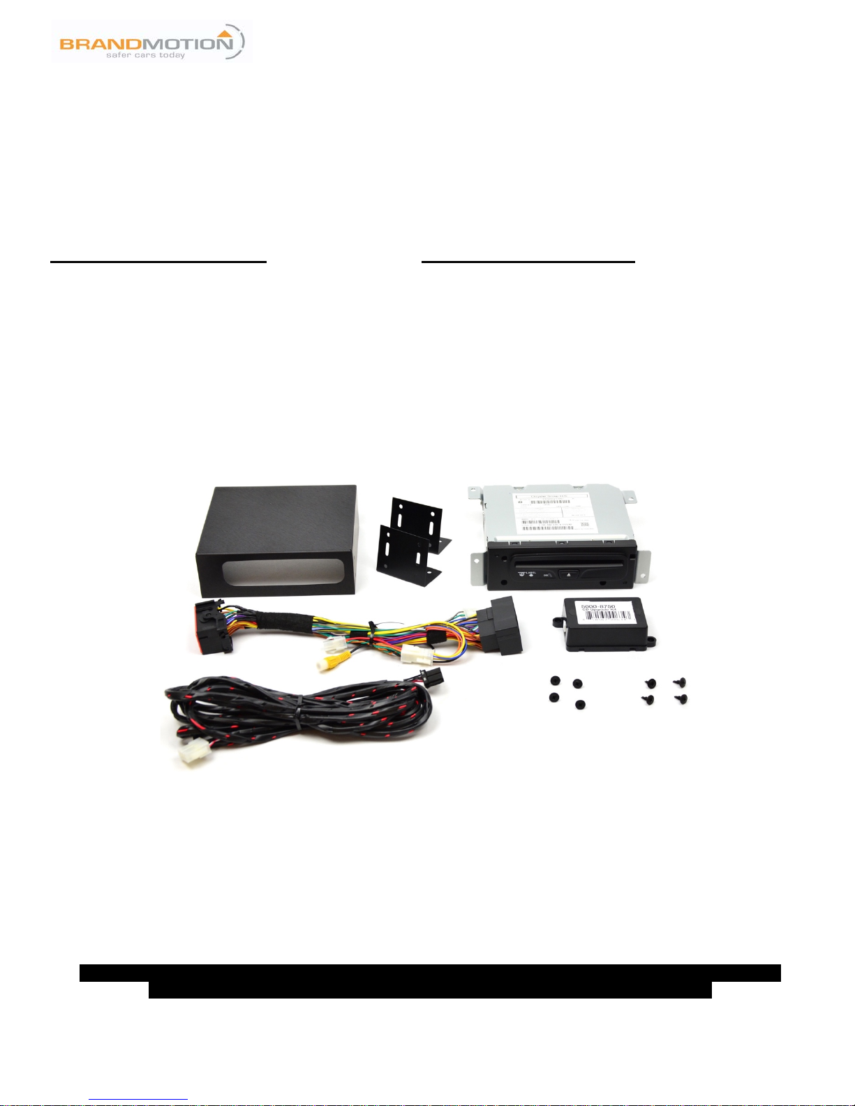
Items Included in the Kit:
Tools & Supplies Needed:
T-harness
OEM Remote CD player
Universal case and bracket mounts
4 self-drilling screws for mounting to metal, 4
stingers for plastic
2 stand-off threaded spacers
(for Pacifica installs)
Remote CD player harness
5000-8750 module to enable CD player
Templates
These instructions
Electrical tape
Zip ties
Plastic panel removal tools
Drill with 1 1/8” step bit or hole saw
Screwdriver
Safety Precautions:
•Work in well ventilated area that is clear of obstructions.
•Secure vehicle with tire chucks in both front and rear of tires.
•Turn vehicle accessories OFF and ensure ignition key is in OFF position.
•Wear safety goggles and snug fitting clothes.
•Use tools only for their intended purpose and which are in good repair.
•Only perform this task if confidence, skill, and physical ability permit.
NOTE: We strive to provide accurate and up-to-date installation instructions. For the latest full color
instructions, as well as an installation video, please visit www.brandmotion.com
INSTALLATION INSTRUCTIONS
5000-8750 Instructions 02-22-17.docx Page 2 of 9GS
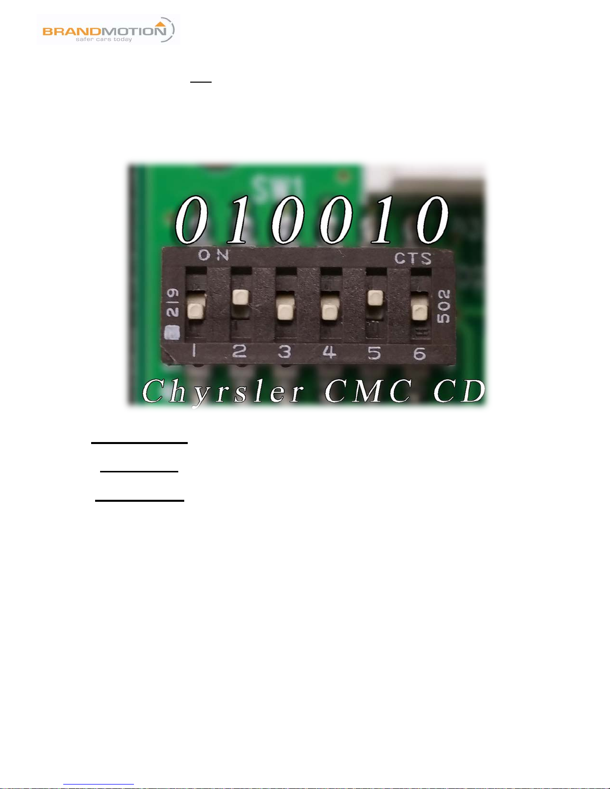
STEP 1: WIRING CONNECTIONS AND MODULE CONFIGURATION
IMPORTANT NOTE:
The radio will NOT function without either the 5000-8750 module or the 6-to-4 pin jumper installed.
Set DIP switches to match the diagram below. Remove radio and install provided 5000-8750 T-harness. You will need to
remove the 6-to-4 pin jumper from the T-harness and replace it with the provided 5000-8750 module. Connect module
and harness BEFORE connecting radio. Install T-harness behind radio and push all wiring and modules back into dash to
allow room for reinstallation of radio. Route CD Player harness to desired CD player mounting location.
FOR RAM TRUCK INSTALLATIONS, PROCEED TO STEP 2A (page 3).
FOR PACIFICA INSTALLATIONS, PROCEED TO STEP 2B (page 5).
FOR ALL OTHER INSTALLATIONS, PROCEED TO STEP 2C (page 7).
INSTALLATION INSTRUCTIONS
5000-8750 Instructions 02-22-17.docx Page 3 of 9GS
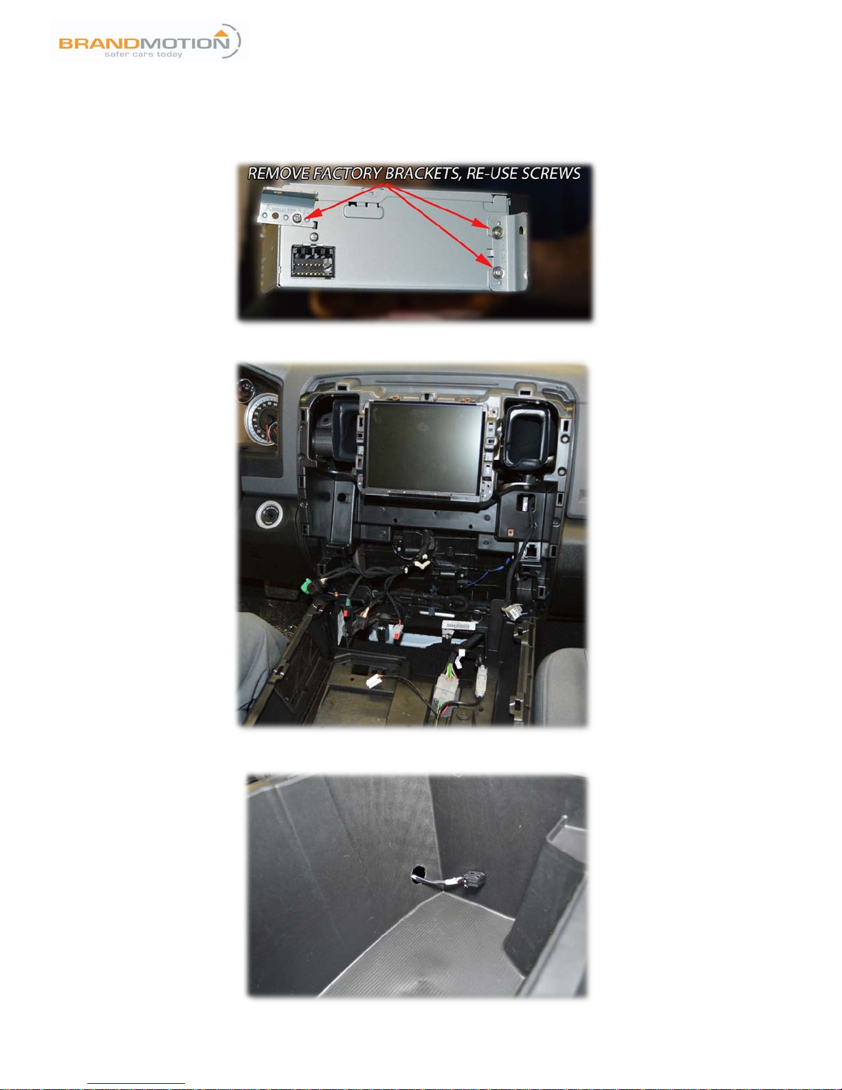
STEP 2A: MOUNTING LOCATION—2013 TO CURRENT RAM TRUCKS
1. This kit includes a universal mounting solution for the CD Player. The brackets are universal and removable.
Remove the factory brackets and use the screws that come with the CD Player to attach the provided brackets to
the housing and into the player.
2. Remove center console/cup holders, radio bezel, and radio.
3. Use provided template to drill hole for wiring.
INSTALLATION INSTRUCTIONS
5000-8750 Instructions 02-22-17.docx Page 4 of 9GS
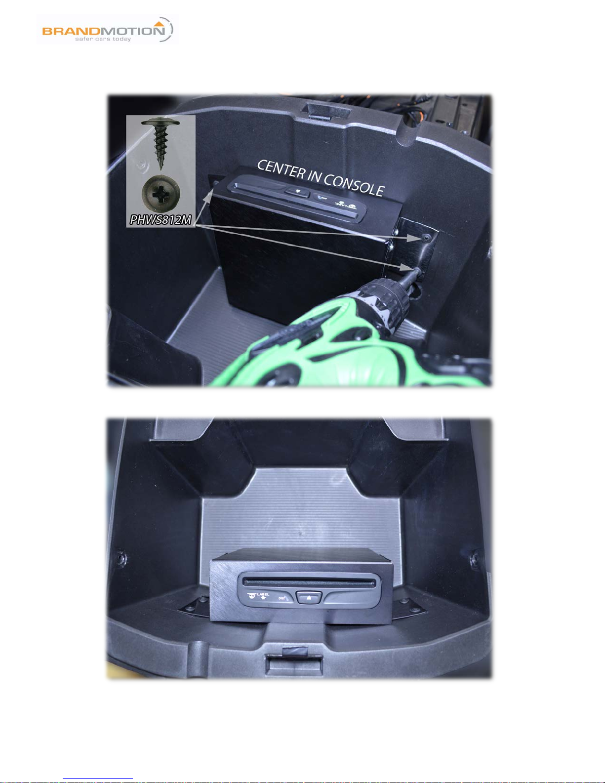
4. Use the (4) PHWS812M Screws provided to affix unit to the plastic console. Pre-drilling is not required. Do not
use the self-drilling screws provided, they are only for use on metal surfaces. Make sure to check clearance on
opposite side of console.
5. Finished CD player mounting should look like the picture below:
INSTALLATION INSTRUCTIONS
5000-8750 Instructions 02-22-17.docx Page 5 of 9GS
STEP 2B: MOUNTING LOCATION—2017 PACIFICA
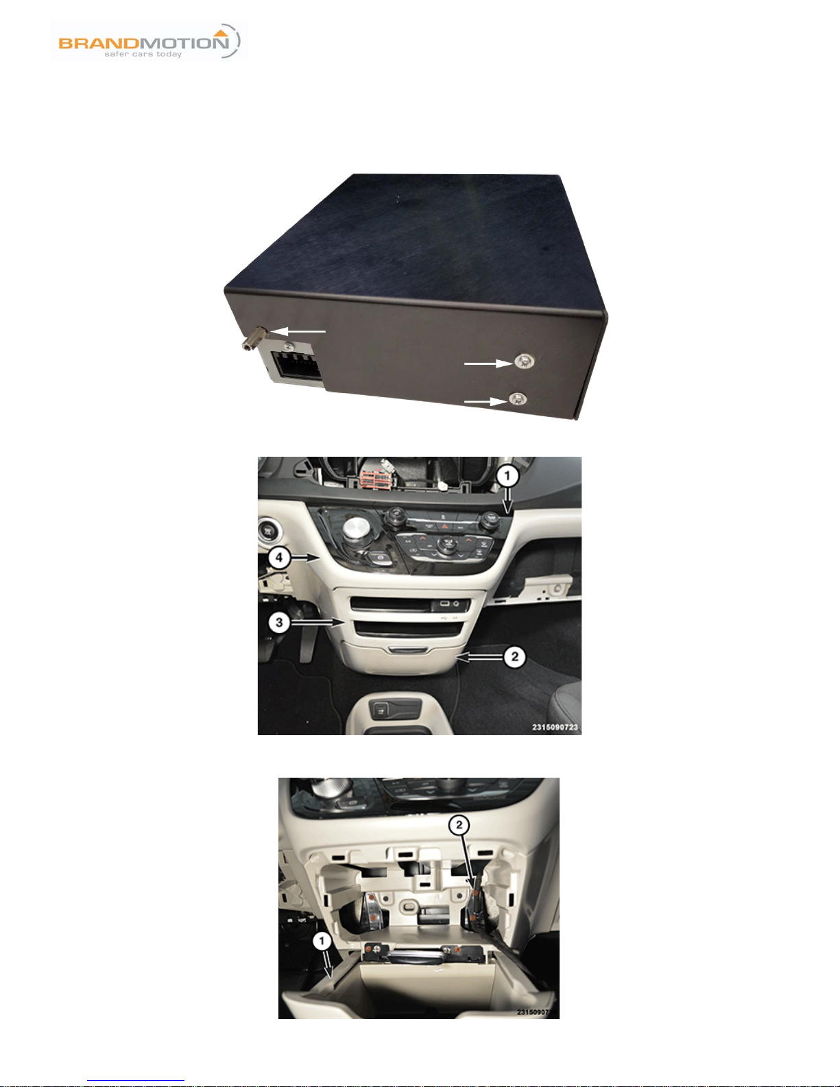
1. Remove the brackets and screws from the CD player. Mount the CD player inside the (provided) aluminum case.
Use the screws you removed earlier to secure the case on the CD player in the front 4 holes. The remaining 2
screws will be used to secure case assembly in vehicle. Install the included threaded stand-offs in the rear-most
holes of the player through the case enclosure.
2. Remove the screw located in the media hub bezel opening (marked “3” in the picture below).
3. Open the bin (marked “2” in the picture below) and use a trim stick to remove the media hub bezel.
4. Remove the six screws (marked as “2” in the picture below) and drop the bin (marked as “1” in the picture
below) down to remove.
INSTALLATION INSTRUCTIONS
5000-8750 Instructions 02-22-17.docx Page 6 of 9GS
5. Remove the change tray from the bin. This will no longer be used.
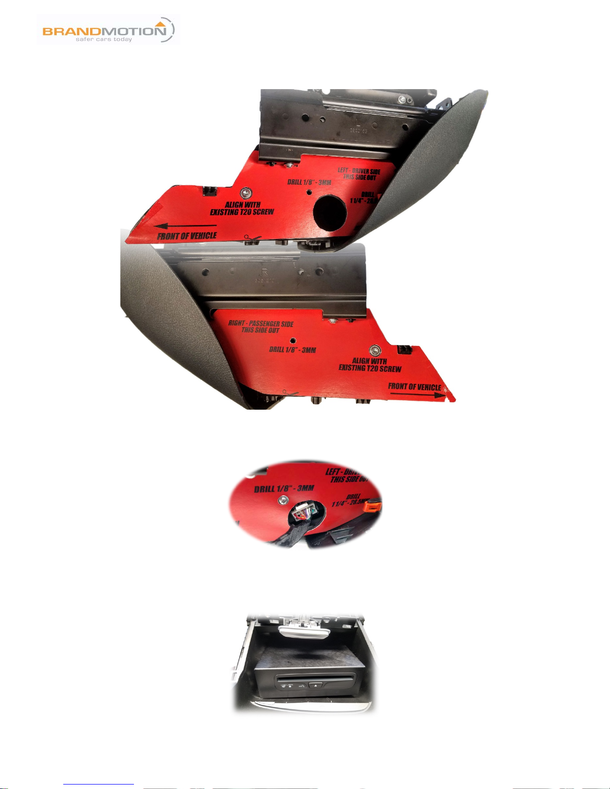
6. Cut out supplied template along black lines.
7. Unsnap plastic bin sides to reveal mounting screws, as pictured below:
8. Apply templates and tape into place.
9. Follow directions on templates to drill (2) 1/8” holes and (1) 1 ¼” hole.
10. Route wiring through 1 ¼” hole and plug into CD player. (This can also be done after installation of CD player.)
11. Install CD player in opening, aligning threaded stand-offs with new 1/8” holes.
12. Use screws removed from CD player in step 1 to secure CD player in place using 1/8” holes and threaded stand-
offs.
13. Reinstall bin sides, reinstall bin in dash and route wiring behind radio. (See step 3 for radio removal.)
14. Leave sufficient slack in wire to allow bin to open and close without pinching or stretching wire.
INSTALLATION INSTRUCTIONS
5000-8750 Instructions 02-22-17.docx Page 7 of 9GS
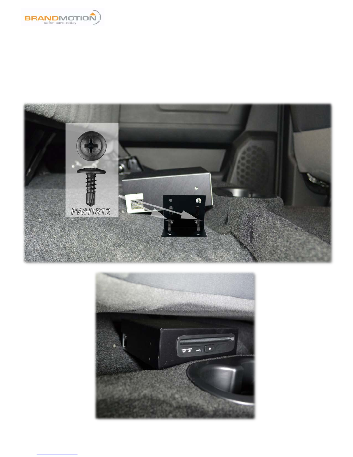
STEP 2C: MOUNTING LOCATION—ALL OTHER VEHICLES
This kit comes with universal brackets for installation. The CD player may be mounted horizontally or vertically. It is
recommended that you discuss mounting options with your customer before performing the installation. The brackets are
also reversible for placement under dash or in a compartment.
MAKE SURE TO CHECK BOTH SIDES OF ALL SURFACES BEFORE DRILLING ANY HOLES OR USING SELF-
DRILLING SCREWS.
Example: RAM truck crew-cab, player mounted under rear seat:
INSTALLATION INSTRUCTIONS
5000-8750 Instructions 02-22-17.docx Page 8 of 9GS
STEP 3: RADIO REMOVAL AND WIRING INSTALLATION
IMPORTANT NOTE:
Make sure wiring is secured and cannot interfere with normal vehicle operation.
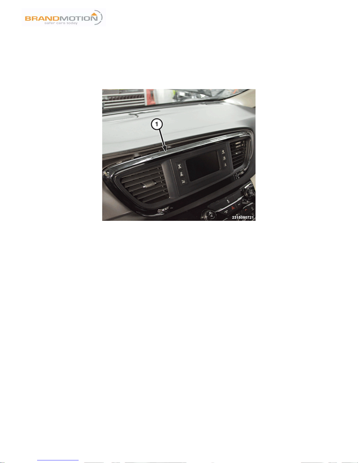
1. Use a plastic trim removal tool to remove the radio screen trim bezel (marked as “1” in the picture below) and
remove the electrical connectors. For 8.4-inch RA3 and RA4 radios, the screen can stay attached to the trim
bezel. For 5.0-inch RA2 radios, it is recommended to remove the radio from the trim bezel.
2. For 8.4-inch RA3 and RA4 radios, proceed to remove the back end of the radio and disconnect the main 52-pin
connector.
3. Route wiring from the CD player and install T-harness behind radio. 5000-8750 module should be installed on
the T-harness at this point.
4. Reinstall radio, screen, and bezel in opposite order and ensure the added wiring and module is securely fastened
in the dashboard behind the radio.
5. Once install is finished, replace all panels and ensure cabling is ran in a way that will not pinch or damage wiring.

INSTALLATION INSTRUCTIONS
5000-8750 Instructions 02-22-17.docx Page 9 of 9GS
STEP 4: RADIO PROGRAMMING AND DEMONSTRATION
“DISC” should become a new source on the customer’s radio within two full power cycles of the vehicle.
If the vehicle and radio do NOT accept programming:
1. Verify DIP switch setting from step 1.
2. With all doors shut and vehicle powered down, disconnect the negative side of the battery. (If equipped with an
Intelligent Battery Sensor (IBS), see dealership workshop manual.)
3. Leave disconnected for 5 minutes.
4. Once reconnected, power on vehicle and allow radio to fully power on.
5. Turn vehicle off, open and close driver door.
6. Allow 5 additional minutes for the vehicle to fully “go to sleep.”
7. Turn vehicle on again and “DISC” should be populated under the SOURCES menu.
8. If no “DISC” icon has appeared, repeat steps 4-6 one additional time.
The 5000-8750 module MUST remain installed in the vehicle for continued operation of the add-on CD player.
For additional assistance, contact Brandmotion Technical Support at 1-734-619-1250 and select option 2 twice.
Other manuals for 5000-8750
1
Table of contents
Popular Car Receiver manuals by other brands


Harman Kardon
Harman Kardon The Counterpoint A-400 Operating and service instructions

Pioneer
Pioneer DEH-4200SD Operation manual

Audiovox
Audiovox Rampage AV-455 Owners and installation manual

Kenwood
Kenwood KRC-2100 instruction manual

Pioneer
Pioneer MEH-P5000R Service manual

JVC
JVC KD-DV6101 Service manual