BrandMotion SUMMIT VIEW SUTV-2020 User manual

User
Manual
Before operating
the
Monitor, please read this manual thoroughly
and retain it
for
future reference.
Content
Product Specifications and Main Functions ........................1
Product Description...........................................................2
Remote Control Function...................................................3
Wiring
Diagram
...................................................................4
Operation Instructions.....................................................4
Product Standard lnstallation.............................................6
Accessories
........................................................................6
Attention
.............................................................................8
Specifications
1. Screen: 7/9/10
.1
inch color TFT LCD screen
2. Resolution: 1024*RGB*600
3. System language: English/ Chinese
4. System: PAUNTSC automatically
5.
Support up
to
4CH 1080P/720P/CVBS input
6. DC 12V~24V power supply
7. Operate temperate: -20°C~70°C
8. Storage temperate:
·30°C
-80°C
9. Housing size(L*W*H): 180*24*121mm(7")/ 235*27*158mm(9")/
251*32*165mm(10.1")
10.Housing size(L*W*H)
of
monitorwith DVR: 180*27.1
*121
mm(?")/
235*33.3*158mm(9")/ 251*32*165mm(10.1")
Main functions
1. DVRfunction(only for monitor with DVR)
2. Recording: support4 channel real time recording
3. Video compression format: H.264
4. Video format: AVI
5. Automatic video recording
6. Recording resolution: 640x480
7. Recording speed: 30FPS
8. Storage: SD memory card(class 10), MAX256G
9. Playback: support to playback
of
each camera
10
. Support Single/Double/Triple/Quad images display
11. Support up to 4CH triggers
12
. Support to adjust the trigger delay time for each camera
13. Support panel buttons and remote control operation
14. 4 PIN/ RCA/ Customized connector
15. Removable sunshade
1
2. Product Description
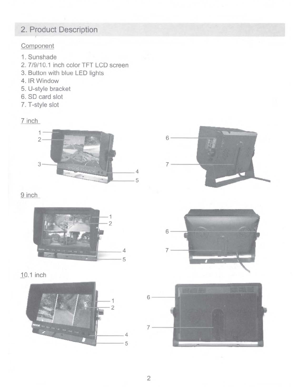
Component
1. Sunshade
2. 7/9/10.1 inch color
TFT
LCD screen
3. Button with blue LED lights
4.
IR
Window
5. U-style bracket
6.
SD
card slot
7. T-style slot
7 inch
9inch
.10.1
inch
1
2
4
---
5
2
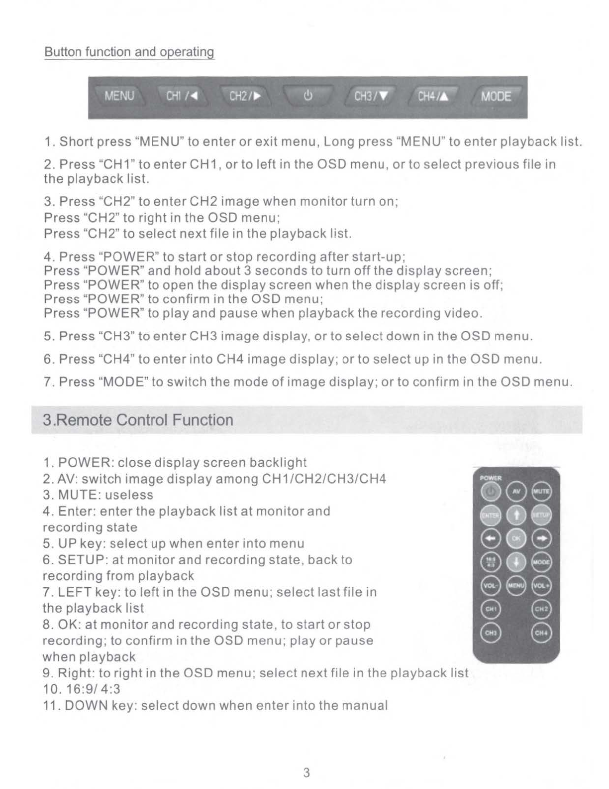
Button function and operating
MENU
CH1
/
◄
CH21
►
<!.>
CH3/
• Oi4/&
MOOE
1.
Short
press
"MENU"
to
enter
or
exit
menu, Long press "MENU"
to
enter
playback
list.
2.
Press
"CH1"
to
enter
CH1,
or
to
left
in
the
OSD
menu,
or
to
select
previous
file
in
the
playback
list.
3. Press "CH2"
to
enter
CH2
image
when
monitor
turn on;
Press
"CH2"
to
right
in
the
OSD
menu;
Press
"CH2"
to
select
next
file
in
the
playback
list.
4. Press "POWER"
to
start
or
stop
recording
after
start-up;
Press
"
POWER
" and
hold
about
3
seconds
to
turn
off
the
display
screen;
Press
"
POWER
"
to
open
the
display
screen
when
the
display
screen
is off;
Press "POWER"
to
confirm
in
the
OSD
menu;
Press "
POWER
"
to
play
and
pause
when
playback
the
recording
video.
5. Press "CH3"
to
enter
CH3
image
display,
or
to
select
down
in
the
OSD
menu.
6.
Press
"CH4"
to
enter
into
CH4
image
display;
or
to
select
up in
the
OSD
menu.
7.
Press
"MODE" to
switch
the
mode
of
image
display;
or
to
confirm
in
the
OSD
menu.
3.Remote Control Function
1.
POWER:
close
display
screen
backlight
2. AV:
switch
image
display
among
CH1/CH2/CH3/CH4
3. MUTE:
useless
4. Enter:
enter
the
playback
list
at
monitor
and
recording
state
5. UP
key
:
select
up
when
enter
into
menu
6. SETUP:
at
monitor
and
recording
state,
back
to
recording
from
playback
7.
LEFT
key:
to
left
in
the
OSD
menu;
select
last
file
in
the
playback
list
8. OK:
at
monitor
and
recording
state,
to
start
or
stop
recording
;
to
confirm
in
the
OSD
menu;
play
or
pause
when
playback
9. Right:
to
right
in
the
OSD
menu;
select
next
file
in the
playback
list
10.
16:9/
4:3
11. DOWN key:
select
down
when
enter
into
the
manual
3

12. MODE key: switch between single image display
or
quad images display
13. VOL- key: useless
14. Menu key: enter into the menu
15. Volume + key: useless
16. CH1: to enter
CH1
display
17. CH2: to enterCH2 display
18
. CH3: to enter CH3 display
19. CH4: to enter CH4 display
4.Wiring Diagram
1.
CH1
2. CH2
3. CH3
4. CH4
5. GND (Black wire)
6. Power (+12V/+24V, Yellow wire)
7. ACC (Red wire)
8. Trigger1 (CH1 , Brown)
9. Trigger 2 (CH2, Green)
10.Trigger 3 (CH3, Blue)
11.Trigger4 (CH4, Grey)
5.OperationInstructions
Main interface instructions
1.
AHD1/AHD2/AHD3/AHD4 image display
2.
f..(•
►
4•1ft11
■
1Itjlij.f
~
·real date and time display
3. recording state prompt and recording time
.....
1 d b 'It .
4. : memorycar
u1
-in
..
5. ~ : memory card not inserted
6. Support single channel video amplification
by
button
or
remote control
or
trigger
4
Operation menu instruction
ll
,<
Settings
5..;.
·11r,
1
:.··
.-;;.;~~<:1f::,~-'~~m1t~'!',f1i~T
►
1f.,::i.
Rotate 01
~ueScrHn
Off
Unguage
English
TimeSt~mp
Off
Aula Switch
Off
Trigger
O.lay
►
2020/01/01 00,10,52
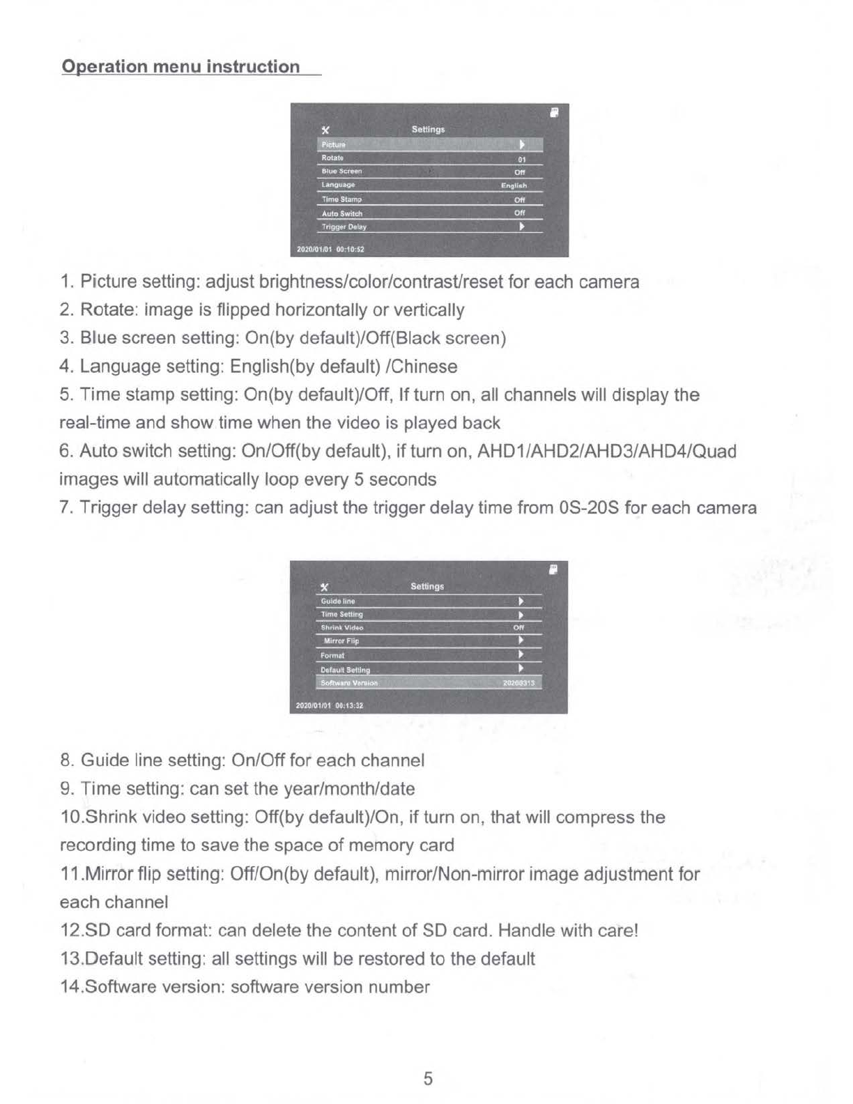
1. Picture setting: adjust brightness/color/contrast/resetfor each camera
2. Rotate: image is flipped horizontally or vertically
3.
Blue screen setting: On(by default)/Off(Black screen)
4. Language setting: English(by default) /Chinese
5. Time stamp setting: On(by default)/Off,
If
turn on, all channels will display the
real-time and showtime when the video is played back
6. Auto switch setting: On/Off(by default),
if
turn on, AHD1/AHD2/AHD3/AHD4/Quad
images will automatically loop every 5 seconds
7.
Trigger delay setting: can adjust the triggerdelaytime from 0S-20S for each camera
8.
Guide line setting: On/Offfor each channel
9.
Time setting: can set the year/month/date
1a.Shrink video setting: Off(by default)/On, ifturn on, that will compress the
recording time to save the space
of
memory card
11.Mirrorflip setting: Off/On(by default), mirror/Non-mirror image adjustment for
each channel
12.SD card format: can delete the content
of
SD card. Handle with care!
13.Default setting: all settings will be restored
to
the default
14.Software version: software version number
5
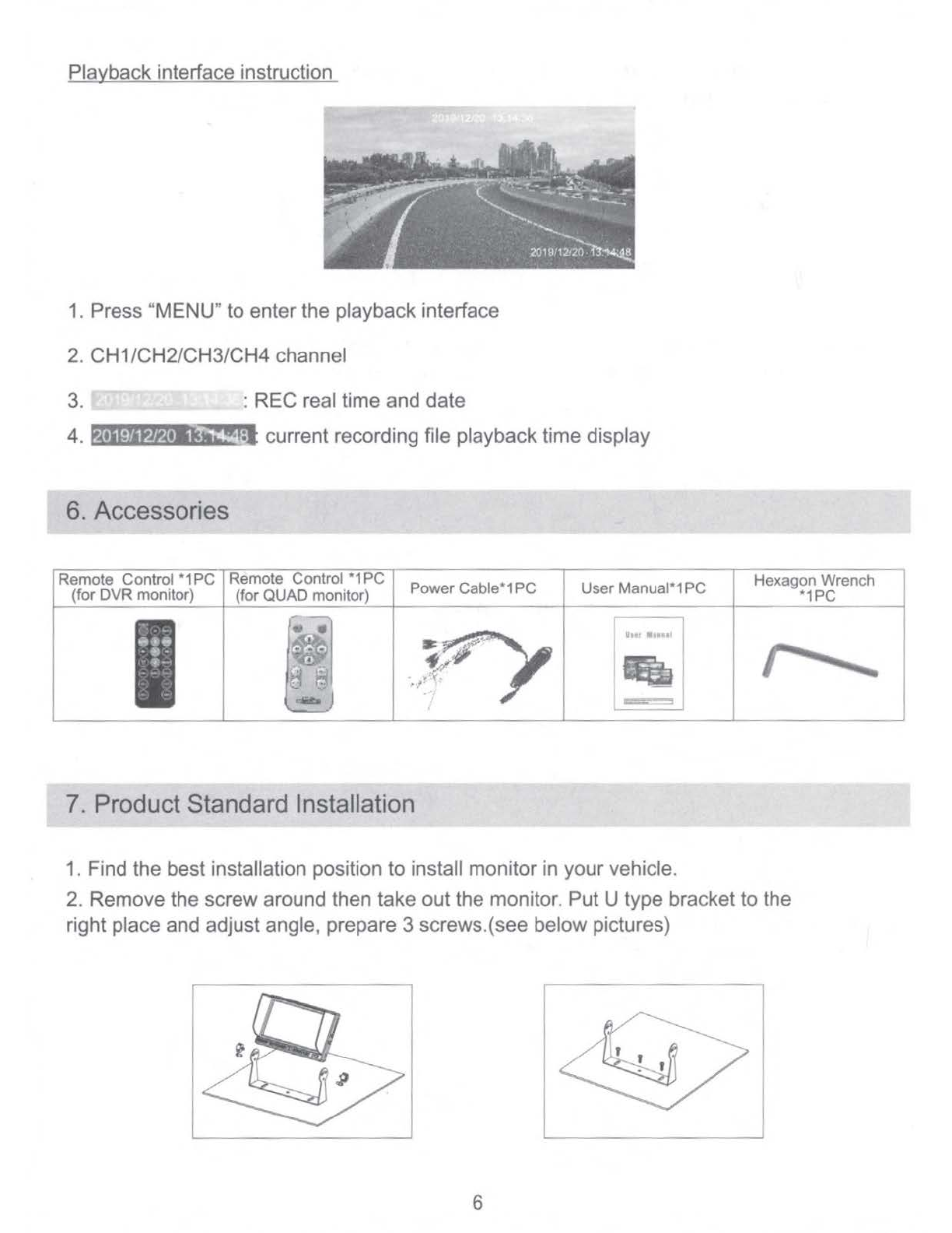
Playback interface instruction
1.
Press "MENU" to enter the playback interface
2.
CH1/CH2/CH3/CH4 channel
3. : REC real time and date
4.
t,t•IPta1;,:.11e»t!f:i
current recording file playback time display
6. Accessories
,-------------.-=-------,-----,-~-=--r---
------r-------~---
-------,
Remote Control
*1
PC Remote Control
*1
PC
(for DVR monitor) (forQUAD monitor) PowerCable*1PC User Manual*1PC
·~·•
•;•
...
~
,.
.~·
lhtt
■
11111
'
===
'
7.
Product Standard Installation
1.
Find the best installation position to install monitor in your vehicle.
Hexagon Wrench
*1PC
2. Remove the screw around then take out the monitor. Put U type bracket to the
right place and adjust angle, prepare 3 screws.(see below pictures)
6

3. Locking the bracket
by
screws. Put the monitor into bracket, adjust angle and
locking it.(see below pictures)
4. Finish installation. The adjustable angel is forward 30 and backward 30.
Usercan adjust a suitable angle by themself.(see below pictures)
1. Firstly please fix the screws with and let fan shaped bracket tight.
(see below pictures)
Tapping screw or machine
screwwith nut.
2.
Secondly put the metal buckle piece on the top
of
the fan-shaped bracket into
the notch
at
the back
of
the monitor.(see below pictures)
~
7

3. Move the bracket to the proper location.(see below pictures)
4.
To
fix the big screws
of
the bracket until to the keep the monitor tight.
(see below pictures)
•
5.
If
users want tochange the direction or angle
of
the monitor, firstly to loosen the
screws on the bottom
of
the bracket. Then move the monitor to the desired location
then fix the screws
on
the bottom
of
the bracket again
.(
see below pictures)
8.
Attention
For
your
safety
.Do
not
watch
the
vedio
or
control
the
monitor
when you are
driving
.Do
not
dismantle
the
product
without
professionals
,You can
consu
-It
after
service
or
send
to
service
dpt
if
your
product
was
broken
.
Warning
:
Please
install
this
product
in legal
place
.
Our
c
ompany
don
't in
charge
for
illegal
installation
.
Attention:When
the
weather
was
cold ,the
monitor
may
be
dark
when
star
-ting
up
,
but
it
will
be
warming
up
later
.
then
the
monitor
will
get
right.
8
Don't press the LCD, which will cause the image distortion
or
faulty. Please use
soft wet cloth clean the LCD gently.
Don't put this product into the wet environment or water, which will lead to short
circuit, unnecessary loss
or
fire.
Please format SD card before insert itto the monitor. And put the SD card into the
monitor under power
off
state.
Please stop recording or cut off the power before take out the SD card, in case there
are any contents lost in the SD card.
9
Installation Instructions - UTV Camera System Page 1/5AR_12_23_20
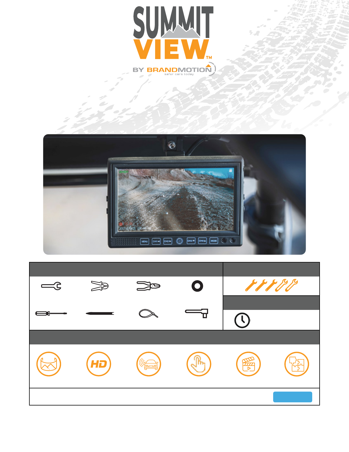
SummitView™ UTV Dual 1080p Camera System
with High Definition 7″ DVR Monitor
SUTV-2020
Install Time
Product Features
Recommended Tools Diculty Level
Unobstructed HD View Eliminates Blind Spots Records as You Drive
3X Wider View Seamless Integration
Full Touch Screen
2hr - 3hr
Wrench
Socket SetScrew Driver Panel Removal Tool Zip Ties
Wire Strippers Wire Cutters Electrical Tape
Questions? Call the Brandmotion technical support line at (734) 619-1250 or CLICK HERE

x2 HD Cameras
Vehicle Application:
Utility Task Vehicles
Part Number: SUTV-2020
Kit A Components for installing the HD Monitor
Kit B Components for installing the O-Road Camera
x1 HD Monitor x1 Power Harness
x3 Mounting Ringsx1 Mounting Plate
x2 Video/Power Harness
Kit Contents
Installation Instructions - UTV Camera System Page 2/5AR_12_23_20

Camera Installation
Mounting hardware installation
Routing the Harness
Part 1
Part 2
1. Remove the 4 Allen screws that are located on
the sides of the camera and remove the camera
mounting bracket and visor.
2. Find an appropriate place to mount the camera.
Line up the foot bracket to ensure that there is
enough space to attach the camera to the body.
3. Attach the mounting foot using either self-
tapping screws or a bolt and nut.
4. Use a 1” hole saw to drill a hole for the camera
harness`
1. Feed the harness through the drilled hole, fit the
grommet to the inside of the hole.
2. Reattach camera and visor to the mounting
bracket. Make sure the camera is oriented UP by
seeing the light sensor on the right side of the
camera when looking at it.
3. Route the camera harness to where the diplay is
located.
4. Connect the 4-pin to RCA cable to the end of the
harness at the display end. (This wont be needed
anymore, all connections are 4 pin)
Camera mounting
Part 2
Vehicle Application:
Utility Task Vehicles
Part Number: SUTV-2020
Installation Instructions - UTV Camera System Page 3/5AR_12_23_20

Monitor Installation and Wiring
Roll Bar Mount
Vehicle Wiring
Camera Wiring
Part 1
Part 2
Part 3
1. Choose the proper size roll bar mounting ring.
2. Use supplied foam and apply to the inner ring of
the bracket.
3. Place mounting ring on desired location. A fair
amount of force might be necessary.
4. Attach the neck of the mounting bracket to
the mounting ring, and tighten the cross bolt.
a). Note: If there is still movement in monitor
bracket mount, lay 1 to 2 strips of electrical tape
between the roll bar and the bracket base.
1. Connect the RED to 12-volt accessory.
2. Connect the BLACK to ground.
3. Connect YELLOW to 12-volt constant power.
1. Connect the GREEN wire to select
parking.
2. Connect the White
3. The BLACK connector is for the power plug.
4.
loop on the camera harness.
12V Constant
12V Accessory
Ground
Vehicle Application:
Utility Task Vehicles
Part Number: SUTV-2020
Installation Instructions - UTV Camera System Page 4/5AR_12_23_20
FAQ Section
1. How do I stop the monitor mount from moving on the roll cage?
We recommend adding a strip of electrical tape to the mounting plate in order to create a tighter t.
2. How do I turn o the monitor?
Hold down the power button for 3 seconds.
3. Is the monitor waterproof?
The cameras are rated for IP 69K, however the montior is not waterproof. We recommend mounting it high on the roll bar to
prevent the possibility of submerging the unit.
4. What type of battery does the remote use?
The remote uses a 2032 3V battery.
WARNING
Cancer and Reproductive Harm
www.P65Warnings.ca.gov
Vehicle Application:
Utility Task Vehicles
Part Number: SUTV-2020
Installation Instructions - UTV Camera System Page 5/5AR_12_23_20
Table of contents
Other BrandMotion Digital Camera manuals


