Bravo Sports GRAVE DIGGER BAD TO THE BONE User manual
For assistance with your assembly call:
www.bravosportscorp.com
or Visit
Toll
Free
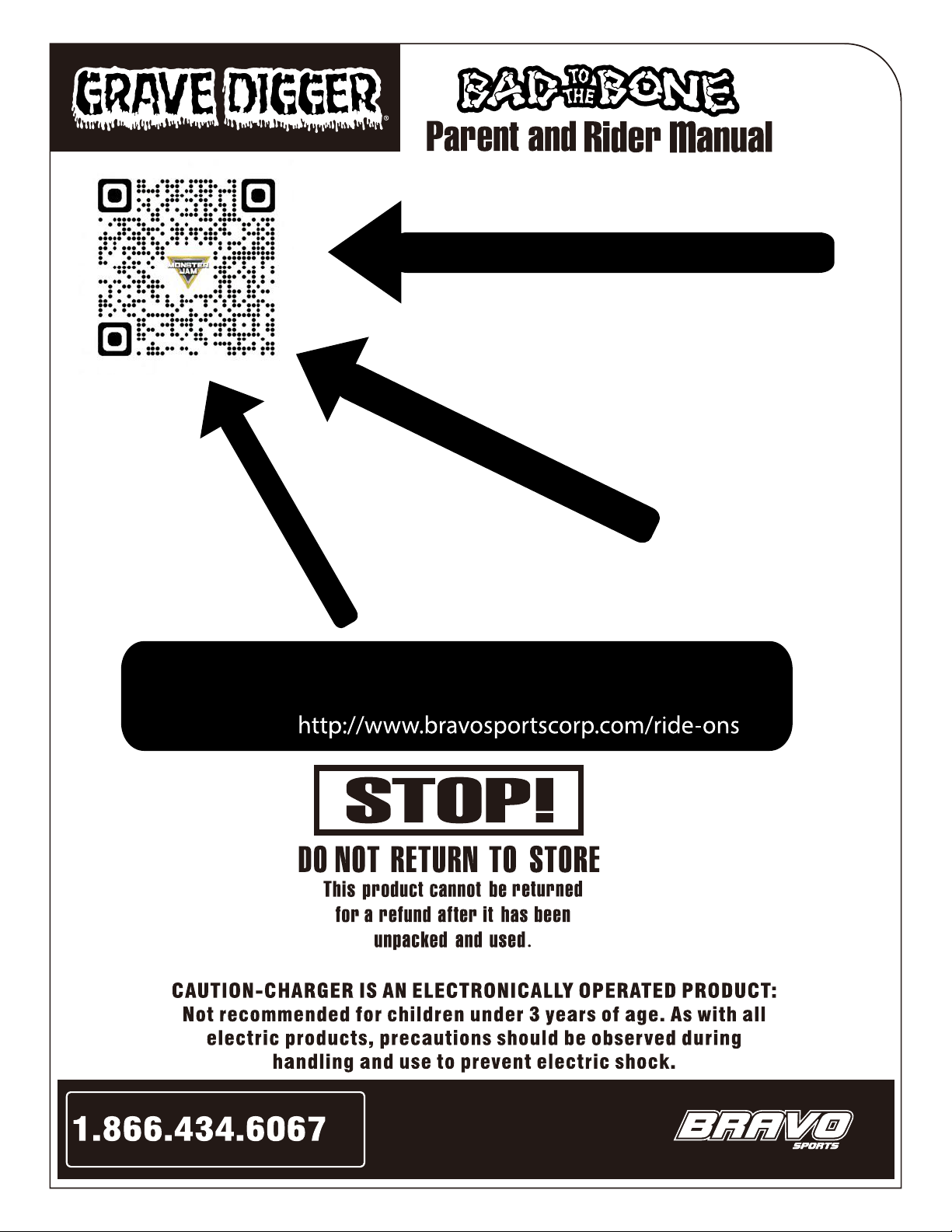
SCAN QR CODE &
SCAN QR CODE
Scan the QR code to see the step-by-step assembly video!!!
For assistance, call Customer Service at 1-866-434-6067
or visit us at
WATCH THE ASSEMBLY VIDEO!!!
MAKES ASSEMBLY EASY!!!
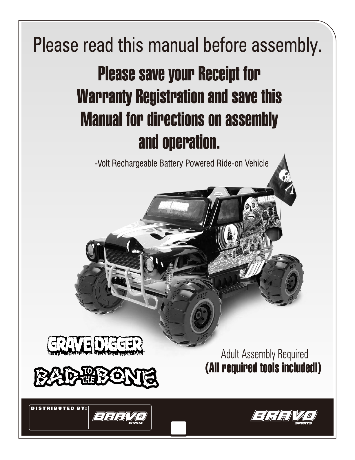
B R A V O S P O R T S
1-866-434-6067 toll-free
www.bravosportscorp.com
12801 Carmenita Rd. Santa Fe Springs, CA 90670
24
1

2
24
1-866-434-6067
1-866-434-6067.
For assistance with your assembly call:
www.bravosportscorp.com
or Visit
Toll
Free
Assembly Instructions
Operation Instructions
How to Replace a fuse
5-6
7
8-21
22
23-24
25
26-27
28-29
30
31
32
4
3
2
7
30
24
24
Bravo Sports Inc.
Bravo Sports Inc.
For assistance with your assembly call:
www.bravosportscorp.com
or Visit
Toll
Free
3
For assistance with your assembly call:
www.bravosportscorp.com
or Visit
Toll
Free
4

All items on this page are included in this package. If you are missing a part
or a tool, please call Bravo Sports Inc. at 1-866-434-6067.
For assistance with your assembly call:
www.bravosportscorp.com
or Visit
Toll
Free
SEAT Driver
Side
Passenger
Side
STEPS
EXHAUST
PIPES
REAR SPACER
REAR BUMPER
FRONT BUMPER
STEERING WHEEL
L
R
5
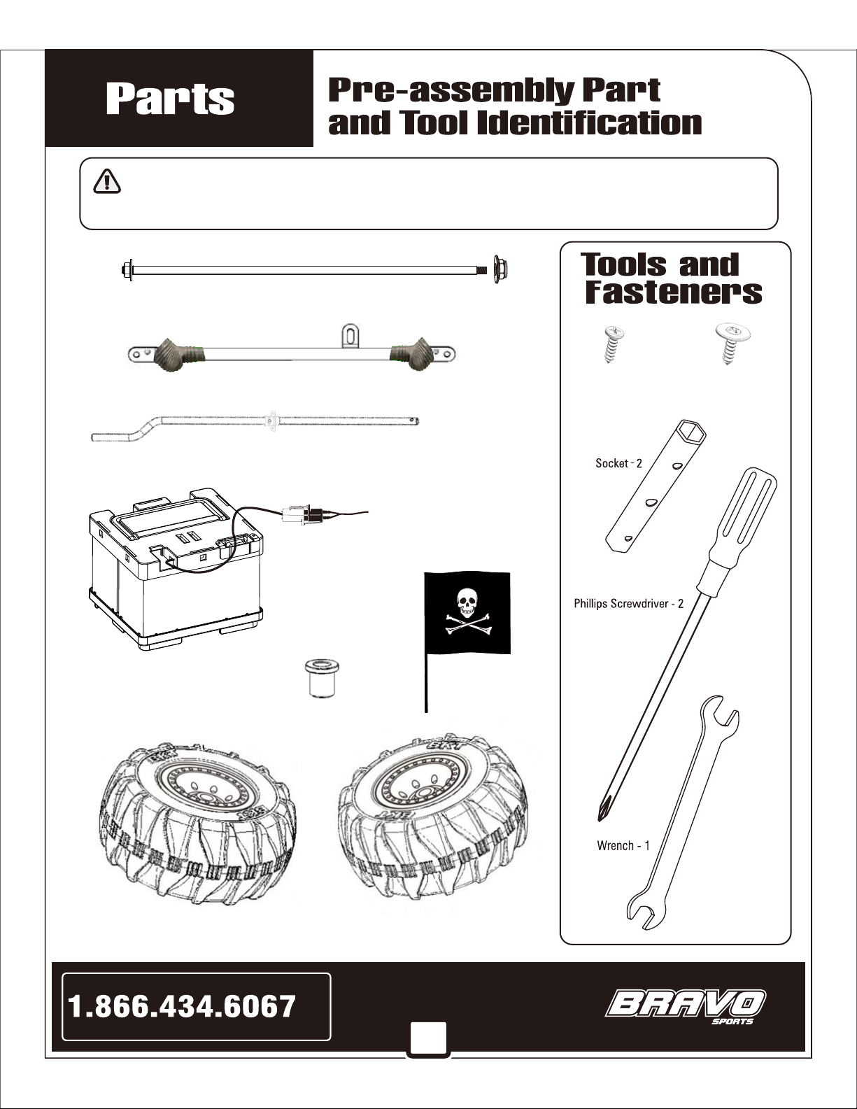
All items on this page are included in this package. If you are missing a part
or a tool, please call Bravo Sports Inc. at 1-866-434-6067.
Wheel ( L ) - 2 Wheel ( R ) - 2
Batter
y B
ox -1
Flag - 1
Battery Connection - 1
For assistance with your assembly call:
www.bravosportscorp.com
or Visit
Toll
Free
Wheel Axle Spacer - 4
Steering Linkage with Boots - 1
Steering Rod - 1
Screws
TYPE “B”
TYPE “A”
Rear Axle - 1 Flange Nut - 1
(8pcs)
(31pcs)
6

1-866-434-6067
For assistance with your assembly call:
www.bravosportscorp.com
or Visit
Toll
Free
7
8
Assembly Instructions
For assistance with your assembly call:
www.bravosportscorp.com
or Visit
Toll
Free
Before you begin...
(You will find some parts UNDERNEATH
the Truck, and the Steering Linkage part
is zip-tied to the frame).
by slowly and carefully rolling it onto its side, and over again so it is upside down.
Remove all plastic zip-ties from the frame and steering linkage (set the steering linkage aside - it will be used later).
(UNDER the Truck are 2 Wheels, the Steering Rod and the Rear Axle - set these aside for later use as well).
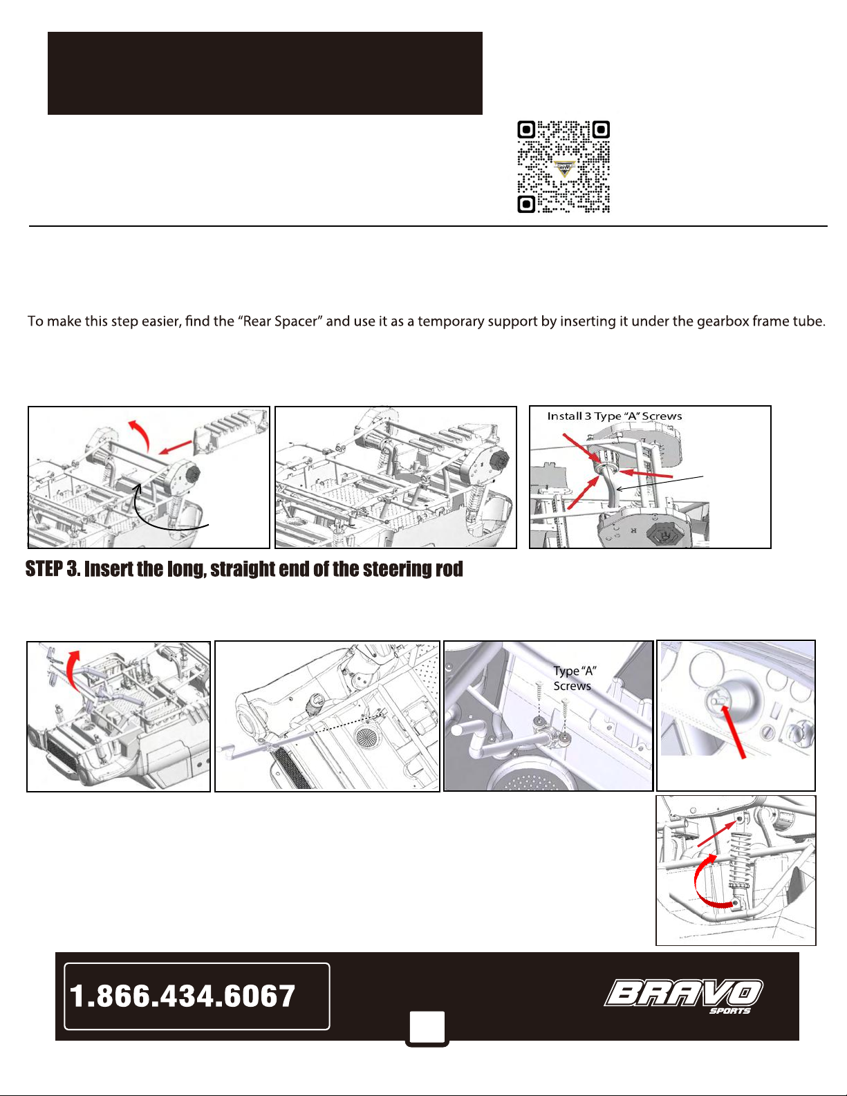
STEP 2. CONNECT MOTOR WIRE COVER TUBES TO MOTOR HOUSINGS
Do this by lifting the Gearbox Frame Tube, and inserting the Spacer (as shown below). Then, allow the frame tube to rest back
down on the spacer. Now, position one of the 2 motor wire cover tubes onto its respective motor housing as shown. Secure
together using 3 type “A” screws. Attach the other motor-wire cover tube to its motor housing with 3 type “A” screws as well.
After both motor wire cover tubes are attached, REMOVE THE SPACER and set it aside for later use.
STEP 4.
STEP 1. - TURN TRUCK UPSIDE-DOWN
by holding up the movable part of the frame, as shown
below. Slide the rod into the opening in the Truck body until the plastic bracket meets the body of the truck and the rod exits
out of the dashboard thru the center hole of the steering wheel mounting pedestal. (Tip the truck up slightly and look under to
verify that the steering rod has come out thru the center hole). Align the plastic bracket and secure with 2 type “A” screws.
Motor Wire
Cover Tube
Gearbox
Frame
Tube
Steering Rod must
exit thru center hole
Remove the hex socket bolts from the unattached ends of both REAR shock absorbers.
With BOTH motor-wire covers securely attached, lift-up the movable part of the frame so the rear
shock absorbers can be rotated up, into position within their respective “U” brackets. Secure in
place using the hex socket bolts. Tighten bolts using the 2 hex wrenches provided.
Remove the hex socket bolts from the unattached ends of both FRONT shock absorbers
Lift-up the movable part of the frame so the front shock absorbers can be rotated up, into position
within their respective “U” brackets. Secure in place using the hex socket bolts. Tighten bolts
using the 2 hex wrenches provided.
STEP 5.
LIFT
INSERT
***PLEASE take the time to layout the parts,
tools and fasteners exactly as shown on pages
5 & 6, so you can learn the names of each
specific part, and which side they belong on.
NEED HELP???
Scan QR Code to watch
step-by-step
assembly video
9
Assembly Instructions
For assistance with your assembly call:
www.bravosportscorp.com
or Visit
Toll
Free
***
PLEASE NOTE - STEPS 1 THRU 17
WILL BE PERFORMED WITH THE
TRUCK UPSIDE-DOWN***
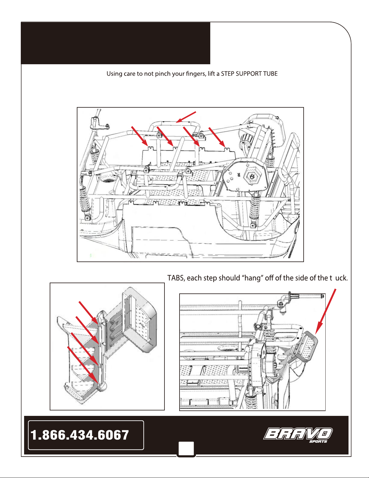
STEP SUPPORT TUBE
4 TABS
***When all 4 SLOTS are properly located over their
4 SLOTS
upwards, so you
can hang each of the 2 STEPS in place. (The STEP shown in the images below is the DRIVER’S SIDE STEP).
LOCATE THE 4 ‘TABS’ on each side of the Truck’s body and THE 4 ‘SLOTS’ in the middle of the STEP, (see image
at bottom of page for SLOT locations) .
STEP 6. HANG THE STEPS
Repeat this to hang the step on the other side.
r
10
Assembly Instructions
For assistance with your assembly call:
www.bravosportscorp.com
or Visit
Toll
Free
***
PLEASE NOTE - STEPS 1 THRU 17
WILL BE PERFORMED WITH THE
TRUCK UPSIDE-DOWN***
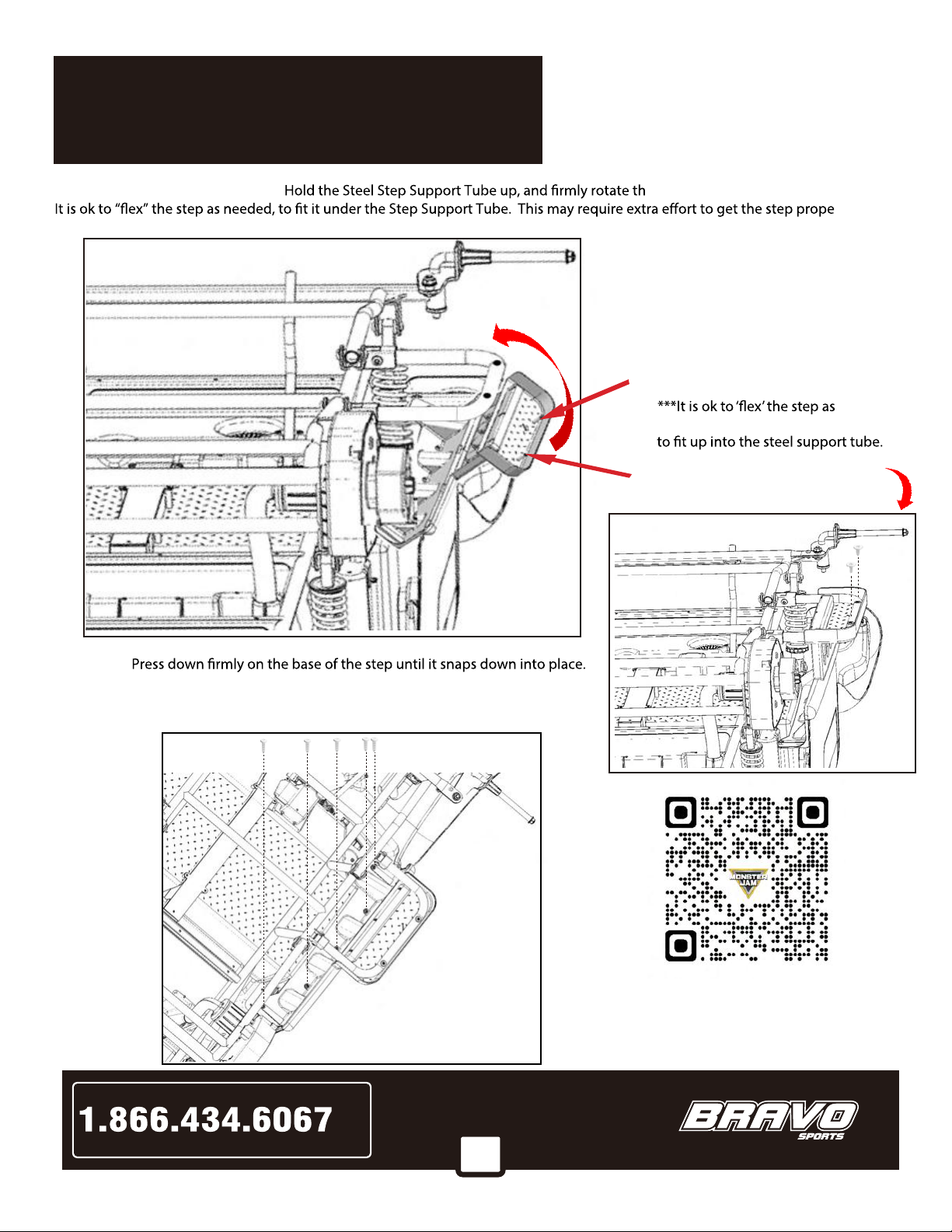
With the step rotated into the
proper position, push down on
the outer edge of the step, and
postion the 2 plastic posts up
into the holes in the steel step
support tube.
needed to get the plastic posts
STEP 8.
STEP 9.
Type “B”
Use 2 type “B” screws to secure the
2 plastic posts to the steel support
tube.
Then, use 5 type “A” screws to secure the base of the step to the under-
side of the truck body, as shown below.
REPEAT STEPS 6 thru 9 to install the STEP onto the other side of the Truck.
e plastic Step upward, so it snaps up under it.
rly in place.
STEP 7. INSTALL THE STEPS
Type “A”
NEED HELP???
Scan QR Code to watch
step-by-step
assembly video

11
Assembly Instructions
For assistance with your assembly call:
www.bravosportscorp.com
or Visit
Toll
Free
STEP 10. Find the 4 mounting posts behind the step assembly:
***
PLEASE NOTE - STEPS 1 THRU 17
WILL BE PERFORMED WITH THE
TRUCK UPSIDE-DOWN***
an “L” and the passenger side has an “R”). Position the openings onto the mounting posts and press into
place. Secure with 4 type “A” screws. The image below shows the Driver’s Side. Repeat Step 10 for the
Passenger Side.
pipe assembly below:
Type “A”

12
Assembly Instructions
For assistance with your assembly call:
www.bravosportscorp.com
or Visit
Toll
Free
STEP 11. To install the Rear Spacer, insert one end of the rear spacer into the empty space between the tail light
and the body of the Truck. Take care to not damage the light or the wiring. Once the spacer is partially
in place, rotate the other end down, into place as well. Some amount of force will be required to get
the part to bend slightly and allow it to snap-down into place.
***
PLEASE NOTE - STEPS 1 THRU 17
WILL BE PERFORMED WITH THE
TRUCK UPSIDE-DOWN***
With the Rear Spacer
properly installed, align
the holes in the body of
the Truck with the holes
in the Rear Spacer, and
secure it in place with
7 type “A” screws.
Type “A”

13
Assembly Instructions
For assistance with your assembly call:
www.bravosportscorp.com
or Visit
Toll
Free
STEP 12. INSTALL THE REAR BUMPER by inserting the 2 long tubes into the ports in the Rear Spacer.
Then, push the 2 short stubs into the ends of the steel frame tubes and secure with 1 type “B” screw on each side.
***
PLEASE NOTE - STEPS 1 THRU 17
WILL BE PERFORMED WITH THE
TRUCK UPSIDE-DOWN***
Type “B”
Screws
NEED HELP???
Scan QR Code to watch
step-by-step
assembly video
14
Assembly Instructions
For assistance with your assembly call:
www.bravosportscorp.com
or Visit
Toll
Free
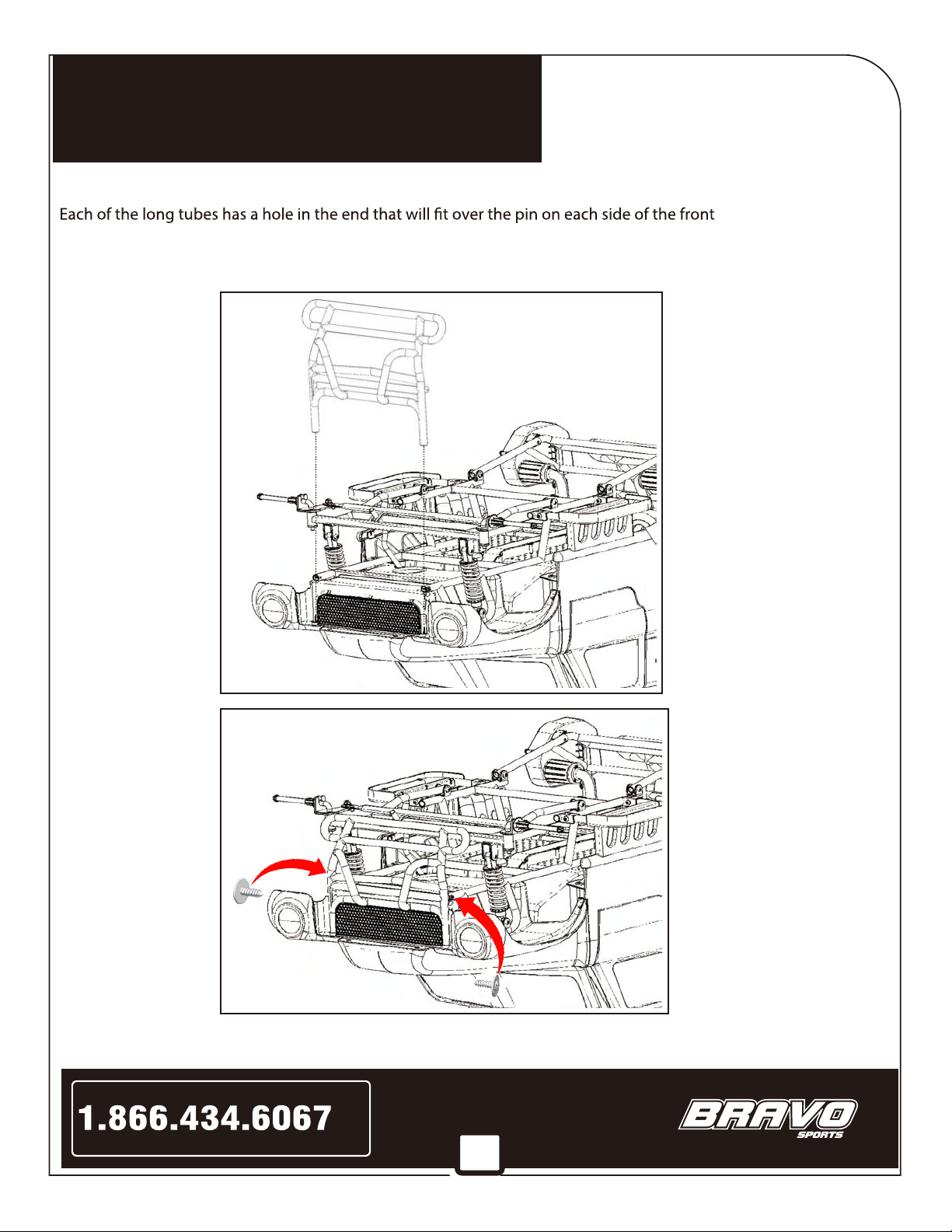
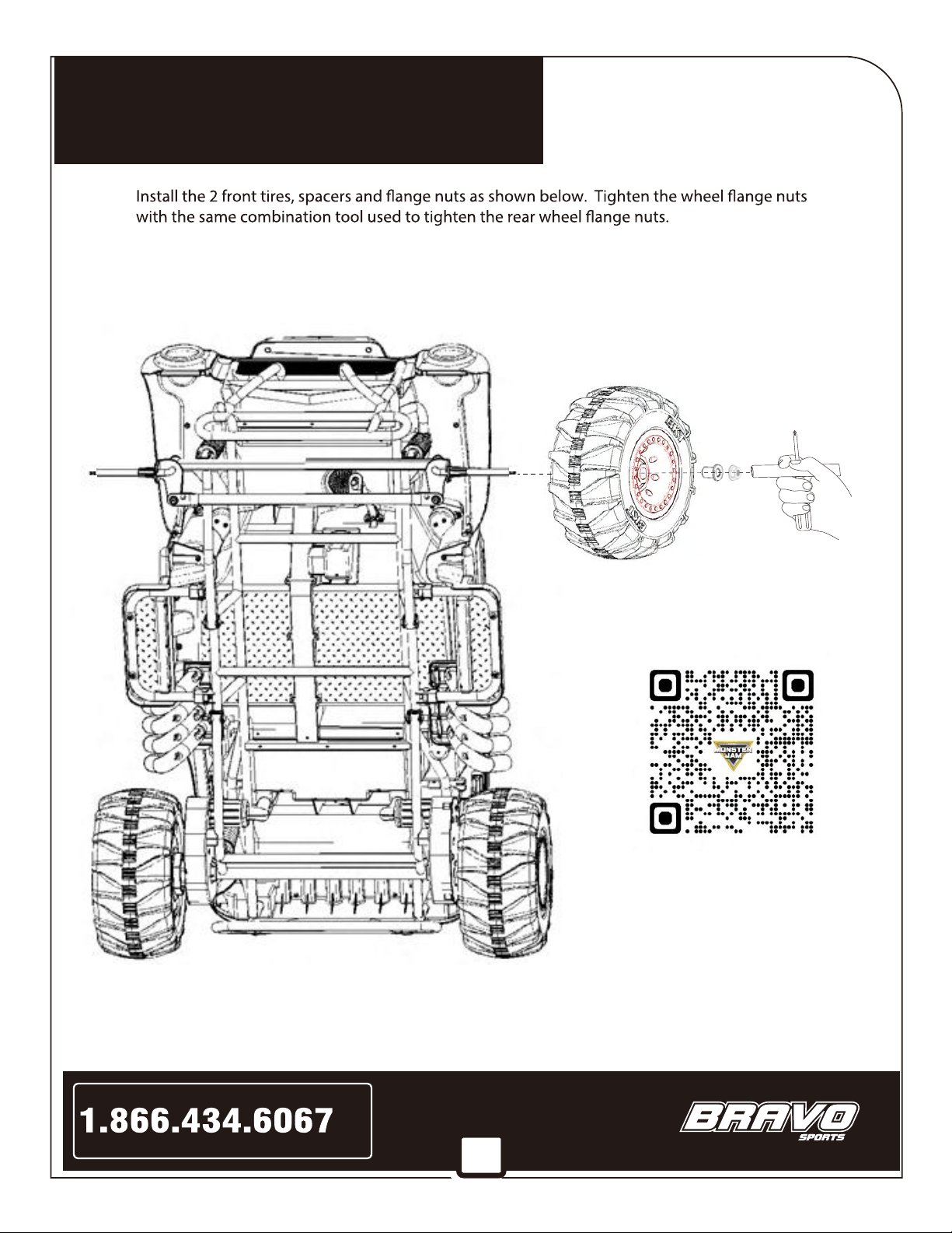
STEP 13. INSTALL THE FRONT BUMPER by inserting the 2 long tubes onto the pins in the front of the Truck.
tubes onto the pins, push the 2 short stubs into the ends of the steel frame
on each side (same as done to install the rear bumper).
***
PLEASE NOTE - STEPS 1 THRU 17
WILL BE PERFORMED WITH THE
TRUCK UPSIDE-DOWN***
Type “B”
Screws
tubes and secure with 1 type “B” screw
grill. After seating the
15
Assembly Instructions
For assistance with your assembly call:
www.bravosportscorp.com
or Visit
Toll
Free
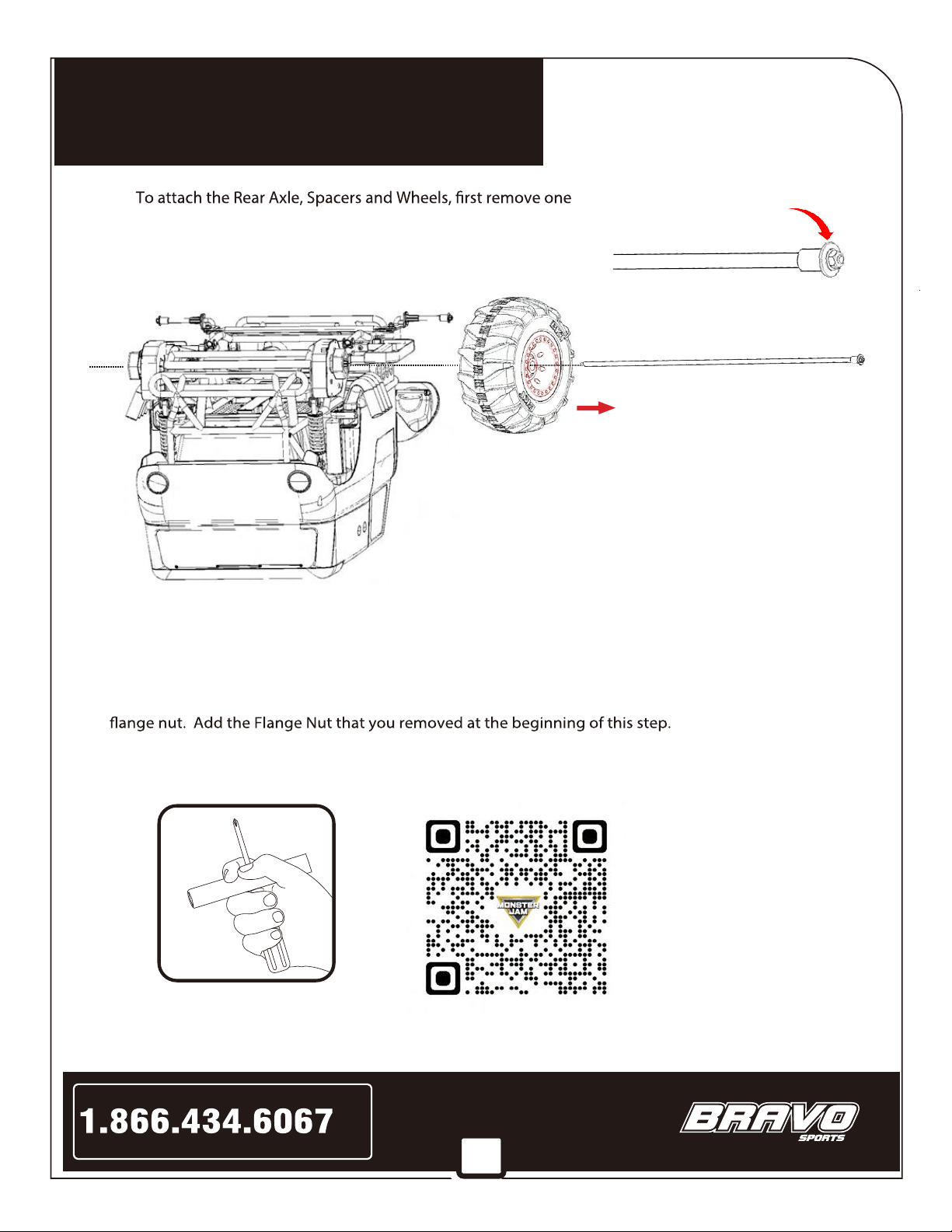
STEP 14.
of the Flange Nuts & Washers from either end of the axle.
Next, slide a spacer onto theAxle until it hits the other Washer
& Flange Nut.
IMPORTANT: Be sure to have the spacer facing the correct direction!
***
PLEASE NOTE - STEPS 1 THRU 17
WILL BE PERFORMED WITH THE
TRUCK UPSIDE-DOWN***
Large diameter of spacer should
touch the Washer & Flange Nut
Next, slide a rear wheel onto the axle so that the letters “BKT” are
facing as shown above.
Then, slide axle through the gearbox until the wheel is correctly
aligned to engage the hexagon shaped drive coupling into the
hexagon recess in the wheel.
NEED HELP???
Scan QR Code to watch
step-by-step
assembly video
TIP: Apply a thin coating of light oil onto the length of the axle
to help it slide thru the gearboxes easier.
Now slide the other rear wheel onto the opposite end of the axle until it is correctly aligned with the
drive coupling. Make sure the letters “BKT” are facing outward.
Then, slide the other spacer onto the axle and push it into the hub of the wheel until the threads of the
axle are exposed. Make sure the large diameter of the spacer is facing outward, so it will touch the washer &
Combine the Socket and Screwdriver as shown in Fig. A below. Use two sets of them to tighten the left
and right nuts at the same time.
Combine socket
and screwdriver as
shown above.
Fig. A
16
Assembly Instructions
For assistance with your assembly call:
www.bravosportscorp.com
or Visit
Toll
Free
Carefully
reposition the
rubber boots
so they cover
which has been
repositioned).
by carefully
sliding the rubber boots so they cover the bolts and
nuts (the boots should look like the boot on the
right side of the linkage in this image >>>>>>>>>
the bolts and
nuts (refer to
boot on right,
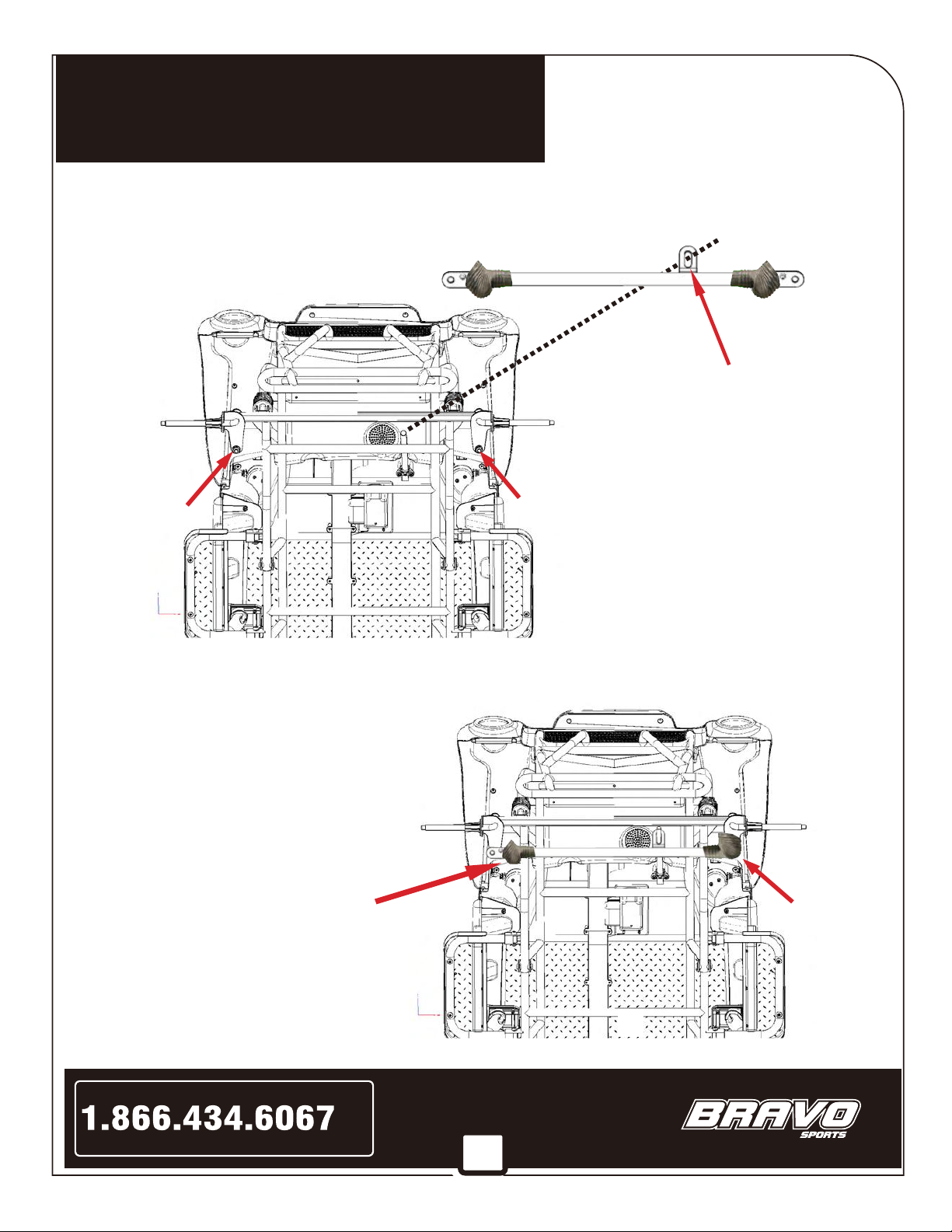
by removing the bolts & nuts from each steering arm. Then place the
Steering Linkage over the Steering Rod so the “Loop” on the linkage captures the end of the Steering Rod.
Secure the Linkage Arm by replacing the bolts & nuts.
The “Loop”
STEP 15. ATTACH STEERING LINKAGE
Remove
Bolt and Nut
Remove
Bolt and Nut
Example of
a properly
repositioned
rubber boot
STEP 16. FIT THE RUBBER BOOTS
***PLEASE NOTE - STEPS 1 THRU 17
WILL BE PERFORMED WITH THE
TRUCK UPSIDE-DOWN***
17
Assembly Instructions
For assistance with your assembly call:
www.bravosportscorp.com
or Visit
Toll
Free
STEP 17.
***PLEASE NOTE - STEPS 1 THRU 17
WILL BE PERFORMED WITH THE
TRUCK UPSIDE-DOWN***
NEED HELP???
Scan QR Code to watch
step-by-step
assembly video

18
Assembly Instructions
For assistance with your assembly call:
www.bravosportscorp.com
or Visit
Toll
Free
Connect the wires coming out of the Truck to the wires coming out of the
Steering Wheel by snapping the connectors together as shown >>>>>>>
MAKE SURE THE CONNECTORS SECURELY SNAP TOGETHER!
pedestal, while guiding the steering wheel down onto the Steering Rod.
hole in the Steering Wheel with the hole in the Steering Rod and secure them together by inserting the
bolt and screwing it into the nut on the other side of the Steering Wheel.
***
PLEASE NOTE - STEPS 18 THRU 22
REQUIRE THE TRUCK TO BE PLACED
ON ALL 4 WHEELS***
STEP 19.
STEP 20.
Now that all 4 wheels have been installed, carefully turn the truck
over, so that it is resting on all 4 wheels, in the normal-use position.
STEP 18. INSTALL THE STEERING WHEEL
NOTE:
***TO MAKE THIS STEP EASIER - OPEN THE DRIVER’S SIDE DOOR TO ALLOW BETTER ACCESS***
19
Assembly Instructions
For assistance with your assembly call:
www.bravosportscorp.com
or Visit
Toll
Free
***
PLEASE NOTE - STEPS 18 THRU 23
REQUIRE THE TRUCK TO BE PLACED
ON ALL 4 WHEELS***
To remove the seat, unscrew the 2 pre-installed
screws at the front of the seat.
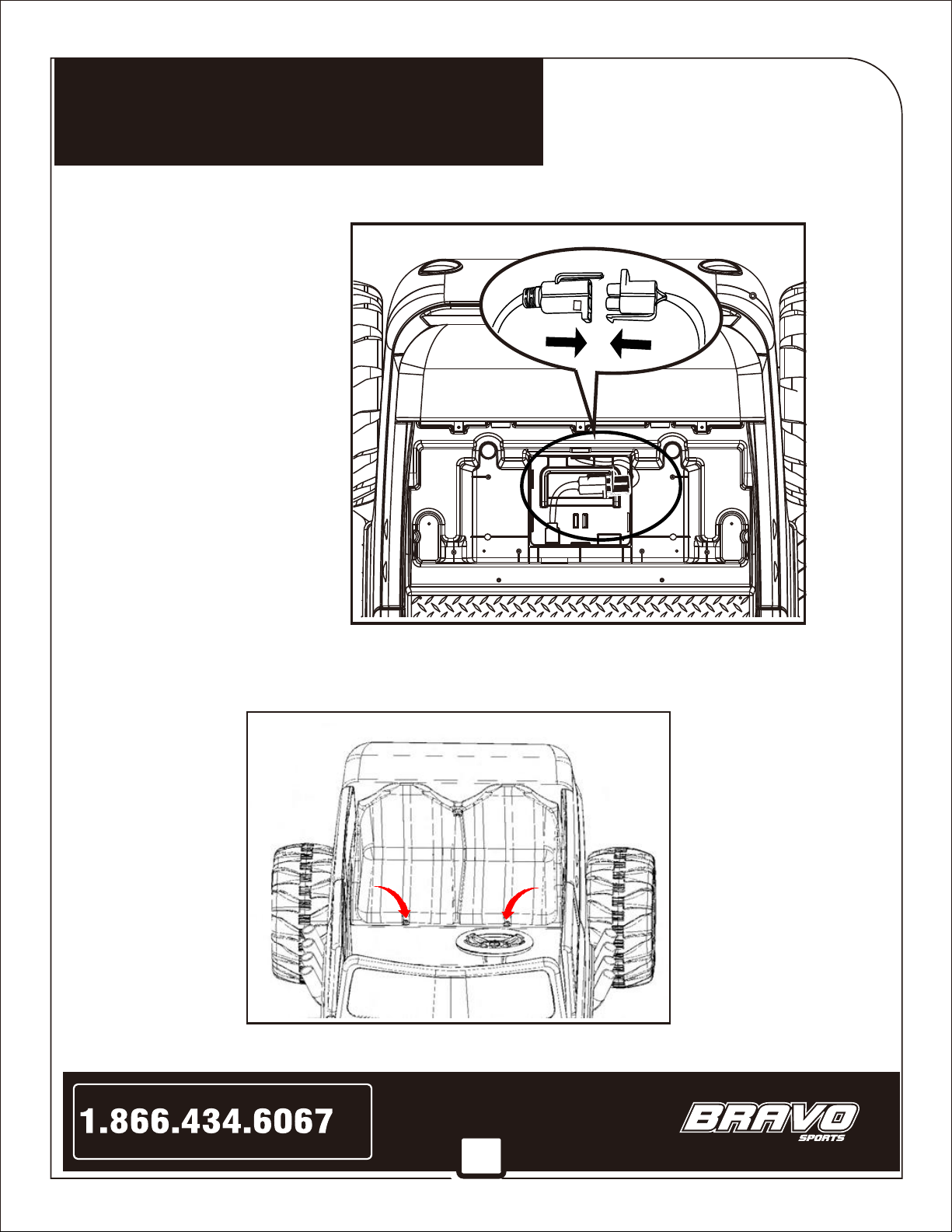
Connect the battery to the Truck by
snapping the connectors together as
shown in the image to the right >>>>
STEP 21. REMOVE THE SEAT & CONNECT THE BATTERY
by sliding the tabs on the lower back of the seat into the slots in the truck body,
then lowering the front edge of the seat down over the battery compartment. Secure it in place with the 2 screws
already installed on the seat.
STEP 22. REINSTALL THE SEAT
Table of contents
Popular Motorized Toy Car manuals by other brands


Carson
Carson 507010 instruction manual

LiteHawk
LiteHawk STING instruction manual

Axial
Axial READY-TO-RUN WRAITH SPAWN ALL TERRAIN STRAIGHT AXLE ROCK RACER 1/10th SCALE ELECTRIC... instruction manual

REVELL
REVELL KIT 1536 Assembly manual

Mattel
Mattel Hot Wheels DAREDEVIL DERBY instructions

Carrera RC
Carrera RC Speed Phantom 2 Assembly and operating instructions