Bravo BMB0900 User manual

BRAVO TECH INC.
Add.: 6185 Phyllis Drive Unit D, Cypress, CA 90630
Phone: 1-714-230-8333
Website: www.bravotechinc.com
Revision: UM·BMB0900-150-SG05·REV.A

©1999-2008 Bravo Tech Inc. All rights reserved.
The “Multi-carrier Outdoor Booster” must be installed only in a restricted access area.
The “Multi-carrier Outdoor Booster” is designed to operate according to the specification of this
User Manual.
Improper installation and operation of this equipment beyond the installation procedures, beyond
the designed operating specifications, and not in compliance with regulatory requirements will
revoke any warranty and may:
Prevent the equipment from performing properly
Violate regulatory RF emissions requirements
Require removal of the equipment from service.

Table of Contents
I
Table of Contents
1SYSTEM INTRODUCTION ....................................................................................................................... 1
1.1 O
VERVIEW
............................................................................................................................................... 1
1.2 S
YSTEM
B
LOCK
D
IAGRAM
...................................................................................................................... 1
1.3 F
UNCTION
................................................................................................................................................ 2
1.4 A
PPLICATIONS
......................................................................................................................................... 3
1.5 S
YSTEM
C
ONFIGURATION
........................................................................................................................ 3
1.5.1 Outline drawing.................................................................................................................................. 4
1.5.2 Interface.............................................................................................................................................. 5
2SYSTEM INSTALLATION ......................................................................................................................... 7
2.1 I
NSTALLATION
O
VERVIEW
....................................................................................................................... 7
2.1.1 Requirements on Installation Site ....................................................................................................... 7
2.1.2 Requirements on Anti-corrosion and Shock-protection ...................................................................... 7
2.1.3 Requirements on Illumination, Ventilation and Fire Protection ......................................................... 8
2.1.4 Power requirements............................................................................................................................ 8
2.1.5 Requirements on Lightning Protecting and Grounding ...................................................................... 8
2.1.6 Installation Preparation ..................................................................................................................... 8
2.2 C
ABINET
I
NSTALLATION
.......................................................................................................................... 8
2.2.1 Installation Requirements................................................................................................................... 8
2.2.2 Installation.......................................................................................................................................... 9
2.2.2.1
Installation on the Wall ...............................................................................................................................9
2.2.2.2
Installation on the Tower...........................................................................................................................10
2.2.2.3
Installation on the Floor............................................................................................................................11
2.3 C
ABLE
I
NSTALLATION
............................................................................................................................ 12
2.3.1 Installation of Power Cable and Grounding Cable .......................................................................... 12
2.3.1.1
Installation Requirements .........................................................................................................................12
2.3.1.2
Installation ................................................................................................................................................12
2.3.2 Installation and Connection of Feeders............................................................................................ 13
2.3.2.1
Installation Requirements .........................................................................................................................13
2.3.2.2
Installation ................................................................................................................................................13
2.4 I
NSTALLATION
I
NSPECTION
.................................................................................................................... 14
2.4.1 Booster Inspection ............................................................................................................................ 14
2.4.2 Cable Inspection............................................................................................................................... 14
2.5 S
YSTEM
T
EST
........................................................................................................................................ 15
3OPERATION AND MONITORING ......................................................................................................... 17
3.1 L
IVE
D
ISPLAY
S
OFTWARE
-
’H
IGH
P
OWER
’ ............................................................................................ 17
3.2 S
OFTWARE
I
NSTALLATION
..................................................................................................................... 17
3.3 P
ORTS
C
ONNECTION
.............................................................................................................................. 19
3.4 S
OFTWARE
O
PERATION
.......................................................................................................................... 20
3.4.1 Start HighPower ............................................................................................................................... 20
3.4.2 Ports Setting ..................................................................................................................................... 20
3.4.3 Status Monitoring ............................................................................................................................. 21

Table of Contents
II
4MAINTENANCES AND MANAGEMENTS ........................................................................................... 24
4.1 S
YSTEM
M
AINTENANCE
........................................................................................................................ 24
4.1.1 Routine Maintenance........................................................................................................................ 24
4.1.2 Indicator Lights ................................................................................................................................ 24
4.1.2.1
Monitoring and Alarm Indicator ...............................................................................................................24
4.1.2.2
Power Amplifier Indicator ........................................................................................................................25
4.2 S
YSTEM
M
ANAGEMENT
......................................................................................................................... 26
4.2.1 Alarm Range Setting......................................................................................................................... 26
4.2.2 Power Amplifier and Low Noise Amplifier Gain Setting and Calculation ....................................... 26
4.2.2.1
Gain Setting ..............................................................................................................................................26
4.2.2.2
Gain Calculation .......................................................................................................................................27
4.2.2.3
Adjustment of PA Gain for BTS Upgrade.................................................................................................28
4.2.3 Alarm and Remote Shutdown Port Specification.............................................................................. 30
5TECHNICAL SPECIFICATIONS ............................................................................................................ 32
6APPENDIX .................................................................................................................................................. 34

Table of Contents
III
List of Figures
F
IGURE
1
O
UTDOOR
B
OOSTER
................................................................................................................................. 1
F
IGURE
2
C
ONFIGURATION OF
O
UTDOOR
B
OOSTER
................................................................................................. 2
F
IGURE
3
S
YSTEM
C
ONFIGURATION
......................................................................................................................... 4
F
IGURE
4
O
UTLINE
D
RAWING
.................................................................................................................................. 5
F
IGURE
5
O
UTDOOR
B
OOSTER
I
NTERFACE
............................................................................................................... 5
F
IGURE
6
D
ISTANCE OF
W
ALL
I
NSTALLING
H
OLES
................................................................................................... 9
F
IGURE
7
I
NSTALLING
I
NFLATABLE
B
OLT
................................................................................................................. 9
F
IGURE
8
T
OWER
M
OUNTING
................................................................................................................................. 10
F
IGURE
9
S
TEEL
B
ELT
............................................................................................................................................ 10
F
IGURE
10
D
ISTANCE OF
F
LOOR
I
NSTALLING
H
OLES
.............................................................................................. 11
F
IGURE
11
F
LOOR
I
NSTALLATION
F
RAME
............................................................................................................... 11
F
IGURE
12
F
LOOR
I
NSTALLATION
........................................................................................................................... 12
F
IGURE
13
I
NSTALLING
P
OWER
C
ABLE AND
G
ROUND
C
ABLE
................................................................................ 13
F
IGURE
14
P
OWER
C
ABLE
C
ONNECTOR
................................................................................................................. 13
F
IGURE
15
C
ABLE
I
NSTALLATION
........................................................................................................................... 14
F
IGURE
16
F
LOW
C
HART OF
S
YSTEM
D
EBUGGING
................................................................................................. 16
F
IGURE
17
P
ORTS
C
ONNECTION
............................................................................................................................. 19
F
IGURE
18
COM
P
ORT
S
ETTING
W
INDOW
............................................................................................................. 20
F
IGURE
19
M
AIN
B
OARD
R
UNNING
S
TATUS
W
INDOW
............................................................................................ 21
F
IGURE
20
P
OWER
A
MPLIFIER
R
UNNING
S
TATUS
W
INDOW
.................................................................................... 23
F
IGURE
21
M
ONITORING
A
ND
A
LARM
I
NDICATOR
L
IGHTS
..................................................................................... 24
F
IGURE
22
P
OWER
A
MPLIFIER
I
NDICATORS
............................................................................................................ 25
F
IGURE
23
P
OWER
A
MPLIFIER AND
L
OW
N
OISE
A
MPLIFIER
G
AIN
S
ETTING
........................................................... 26
F
IGURE
24
A
LARM AND
S
HUTDOWN
P
ORT
............................................................................................................. 30
List of Tables
T
ABLE
1
O
UTDOOR
B
OOSTER
C
OMPONENTS
............................................................................................................ 2
T
ABLE
2
O
UTDOOR
B
OOSTER
I
NTERFACE
D
ESCRIPTION
........................................................................................... 6
T
ABLE
3
M
ENU
B
UTTON
D
ESCRIPTION
................................................................................................................... 21
T
ABLE
4
M
AIN
B
OARD
S
TATUS
D
ESCRIPTION
......................................................................................................... 22
T
ABLE
5
P
OWER
A
MPLIFIER
S
TATUS
D
ESCRIPTION
................................................................................................. 23
T
ABLE
6
S
PECIFICATION OF INDICATOR LIGHT
........................................................................................................ 25
T
ABLE
7
D
ESCRIPTION OF
P
OWER
A
MPLIFIER
I
NDICATOR
L
IGHTS
.......................................................................... 25
T
ABLE
8
A
LARM
R
ANGE
S
ETTING
.......................................................................................................................... 26
T
ABLE
9
V
ALUE
S
ETTING OF THE
4
B
IT
B
INARY
C
ODE
S
WITCH
.............................................................................. 26
T
ABLE
10
S
YMBOL
D
ESCRIPTION
........................................................................................................................... 27
T
ABLE
11
S
PECIFICATION OF ALARM AND REMOTE SHUTDOWN PORT
..................................................................... 30

System Introduction
1
1 System Introduction
1.1 Overview
Bravo Tech Inc's Multi-Carrier High Power Outdoor Booster provides higher downlink EIRP to
extend the coverage of existing sites. The booster is weather resistant, has an advanced thermal
management system and is capable of operating under IP54 environmental extremes. It works at
the frequency of 890-915MHz (uplink) and 935-960MHz (downlink) with the Max input power of
43dBm.
Figure 1 Outdoor Booster
1.2 System Block Diagram
The following figure shows the system block diagram of the multi-carrier outdoor booster.

System Introduction
2
Figure 2 Configuration of Outdoor Booster
The system is composed of a downlink MCPA, duplexers, LNA, attenuator, bypass switch, control
assembly, modem and power supply.
Table 1 Outdoor Booster Components
Item Components Qty
1 Downlink multi-carrier power amplifier 1 PCS
2 Duplexer 2 PCS
3 LNA (built-in the filters) 2 PCS
3 Attenuator 1 PCS
4 Bypass Switch 1 PCS
5 Control assembly 1 PCS
6 Modem 1 PCS
7 Power supply 1 PCS
1.3 Function
This product has the following functions:
Amplifies downlink signal power up to 150W, so as to extend the coverage of BTS.
Amplifies uplink signal, reduces BTS noise figure and improves uplink sensitivity.
Auto by-pass function.
Built-in input attenuator eliminates the need of changing BTS ’S output power.
Extensive system monitor and control.

System Introduction
3
1.4 Applications
Coastlines and large lakes.
Areas far from city center, such as remote countryside.
Long and narrow districts, such as highway, railroad, sea-route.
Rural areas, such as grassland and desert.
Areas where macro-BTS is difficult to be built and coverage of micro-BTS is not enough,
such as mountainous region, foothill, highland.
Areas where the coverage of micro-BTS or micro-cell is not good, such as blind spots of
micro-cell coverage.
Building coverage gaps between networks.
Large area of low population density.
Improving coverage into zoning restricted housing areas.
1.5 System Configuration
The system configuration of a multi-carrier outdoor booster is shown in Figure 3.

System Introduction
4
Figure 3 System Configuration
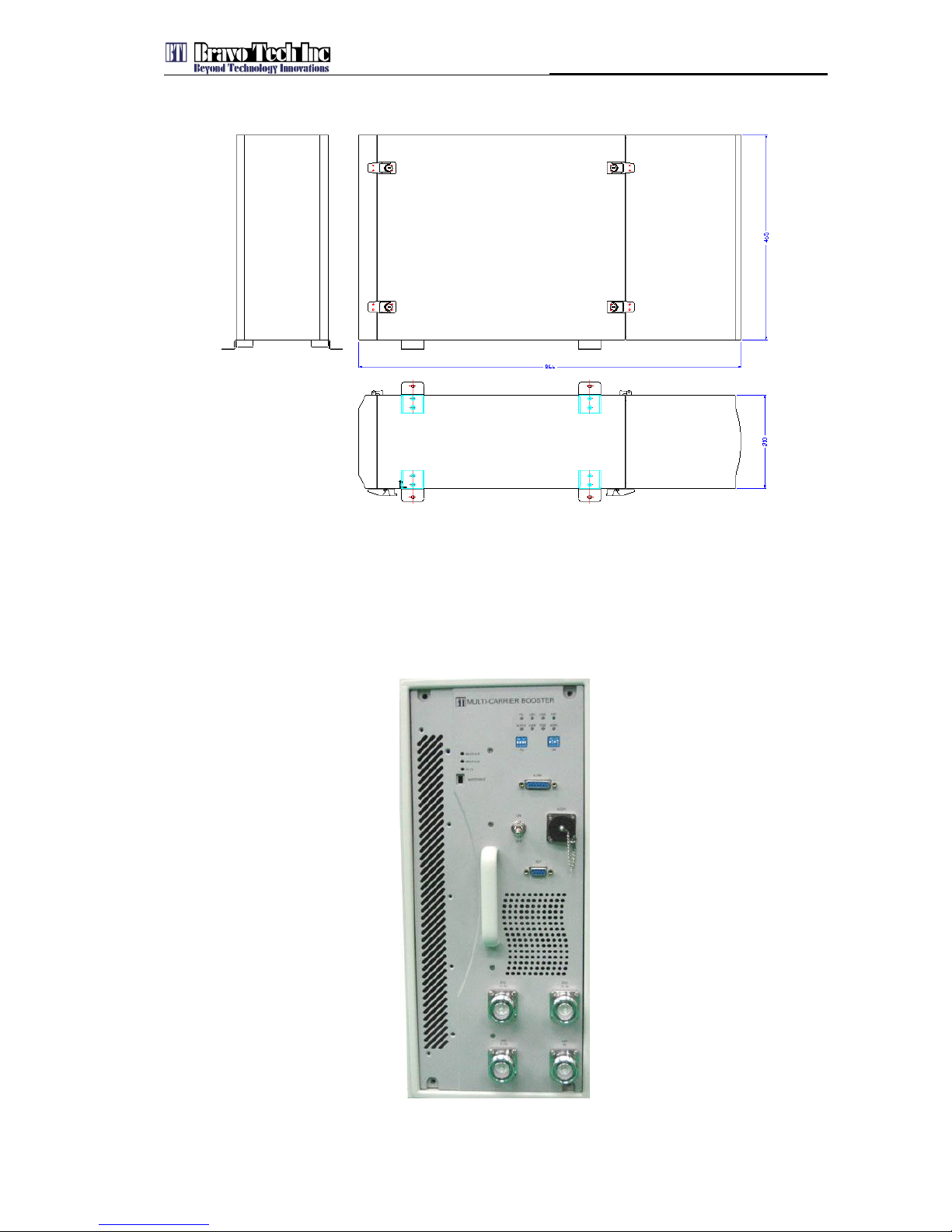
1.5.1 Outline drawing
Figure 4 shows the outline drawing of outdoor booster. Dimensions of outdoor booster are
210mm(8.25”) x 465mm(18.3”) x 866mm(34.1”) (H x W x D)
OUTDOOR
BOOSTER
Antenna Antenna
BTS
Multi-Carrier
Outdoor Booster
ANT0
TX/RX
ANT1
RX1
BTS0
TX/RX
BTS1
TX/RX
System Introduction
5
Figure 4 Outline Drawing
1.5.2 Interface
The interface of the outdoor booster is shown in Figure 5.
Figure 5 Outdoor Booster Interface

System Introduction
6
Table 2 Outdoor Booster Interface Description
Interface Description
AC220V Input power interface for 220V AC
BTS0
TX/RX Connect to BTS main TX/RX port
BTS1
TX/RX Connect to BTS diversity TX/RX port
ANT0
TX/RX Connect to main antenna (TX/RX)
ANT1
RX Connect to diversity antenna (RX)
ALARM ALARM output port(Form C alarms)
TEST Test port

System Installation
7
2 System Installation
This chapter introduces the installation of multi-carrier outdoor booster
Installation steps are as the following chart::
Installation
Preparation
Booster Installing and
Cables Connection
Installation Inspection
System Testing &
Debugging
2.1 Installation Overview
2.1.1 Requirements on Installation Site
The outdoor booster could be installed on the wall or floor, and it should be installed close to the
antenna. The requirements of installation site are following:
The installation site should be non-corrosive.
If the cabinet should be mounted on the wall, the wall’s bearing capacity must be more
than 55kg(122lb). Concrete and brick wall are recommended.
2.1.2 Requirements on Anti-corrosion and Shock-protection
To safeguard products and operators, the installing location must be kept away from caustic or
poisonous pollutants. If the site can’t meet seismic, it must be properly reinforced

System Installation
8
2.1.3 Requirements on Illumination, Ventilation and Fire Protection
The installation site should have enough illumination for installation and maintenance needs.
Flammable and explosive material should not be near to the site.
2.1.4 Power requirements
Nominal voltage: 220V AC. Variety range: 180-264 V AC, 47-63 Hz Single Phase.
The power consumption of outdoor booster is about 1,300W. Be certain to select a fuse or a
breaker with the proper capacity. A 10 or 15 ampere breaker is recommended.
2.1.5 Requirements on Lightning Protecting and Grounding
The cross section of grounding cable should be no smaller than #4AWG(25mm2). The grounding
cable should be connected to each ground directly without any splices. Keep the grounding cable
as short as possible.
2.1.6 Installation Preparation
The following tools will be used for a successful installation:
A multimeter
Philips screwdrivers
Flat blade screwdrivers
Wrenches
A Drill
A VSWR testing devices
N adapters
RF testing cables
Power meter (part of hand-held tester)
2.2 Cabinet Installation
2.2.1 Installation Requirements
Unused circuit breaker
Convenient maintenance access
System Installation
9
Sufficient space for installation
2.2.2 Installation
Caution
The following high-altitude operation should be only performed by qualified personnel under well protection.
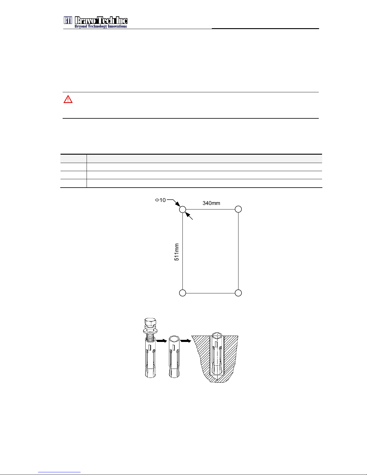
2.2.2.1 Installation on the Wall
Step Operations
1
Drill 4 holes (Ф10) as shown in Figure 6,
2
Install 2 expansion bolts as shown in Figure 7.
3
Mount the cabinet on the wall
Figure 6 Distance of Wall Installing Holes
Figure 7 Installing Inflatable Bolt

System Installation
10
2.2.2.2 Installation on the Tower
Step Operations
1 Fix the tower mounted bracket with the booster as shown in Figure 8
2 Mount the cabinet on the tower
3 Assemble the bracket and the tower with two long bolt
4 Additional, fix the bracket with the tower by using steel belt as shown in Figure 9
Figure 8 Tower Mounting
Figure 9 Steel Belt

System Installation
11
2.2.2.3 Installation on the Floor
Step Operations
1
Drill 4 holes (Ф10) as shown in Figure 10
2
Install 2 expansion bolts as shown in Figure 7.
3
Assemble the bracket and mount the cabinet on the bracket by using the M8*16 bolt. Mount the bracket on
the floor. (Notes: Mounting the bracket before mounting the cabinet on the bracket is acceptable.)
Instructions:
1) Hold mount in place;
2) Make holes;
3) Drill;
4) Install expansion bolts (concrete anchors);
5) Bolt the mount into place.
Figure 10 Distance of Floor Installing Holes
Figure 11 Floor Installation Frame
Make drill

System Installation
12
Figure 12 Floor Installation
2.3 Cable Installation
2.3.1 Installation of Power Cable and Grounding Cable
2.3.1.1 Installation Requirements
Note
The NEC(National Electrical Code) does not allow signal wires to share the same conduit with power wires unless
the signal cable’s voltage range is equal to the power wire’s voltage range.
Avoid bundling signal cable and grounding cable/power cable, keep them separate.
The power cable and grounding cable are supplied, the connectors for the booster end of
power is supplied.
Check open and short circuit before installing the power cable.
2.3.1.2 Installation
Attention
All the power switchs must be switched off before cable installation.

System Installation
13
The installation of power cable and grounding cable is shown in Figure 13. The grounding cable
should be green or yellow-green colored copper cable, with section larger than 4AWG(25mm2)
and resistance lower than 0.5Ω.
Figure 13 Installing Power Cable and Ground Cable
The connection of power cable connector is shown as following figures.
L – Brown
N – Blue
Figure 14 Power Cable
GND – Yellow
Figure 15 Power Cable Connector
2.3.2 Installation and Connection of Feeders
2.3.2.1 Installation Requirements
Shut down the base station and transmitters.
Marking the feeder by label after installation.
2.3.2.2 Installation
The cable installation and connection is shown in Figure 15.

System Installation
14
Figure 16 Cable Installation
2.4 Installation Inspection
2.4.1 Booster Inspection
Item Description
1 Stable and normal.
2 Properly fastened to wall or floor.
3 Screws and nuts screwed tightly, without missing flat washers and spring washers. Spring washers must be
on the top of flat washers.
4 No cable damage.
5 Clean, no smudges or dust.
6 Connections between metallic configurations must be reliable, to assure the reliable electric connectivity.
2.4.2 Cable Inspection
Item Description
1 The connection of the cable is tight, not loose or damaged.

System Installation
15
Item Description
2 The cable shell not damaged.
3 Grounding cable is connected properly.
4 Cables are dressed neatly, power kept separate from signal.
5 The minimum bending radius of the cable is proper. (Shouldn’t be less than twenty times of the cable’s
diameter.)
2.5 System Test
Test the system after the device was installed and inspected.
Test steps for Outdoor Booster:
VSWR testing (sweep test of cables and antenna)
Effect testing: DT/CQT testing
Region optimize: base on the OMC-R statistic data, adjusting the base station’s physical
parameter, regional parameter and switch parameter. So that the system can work
optimally..
Startup setting: uplink and downlink gain setting. To see the detail in the section 4.2.2
Power Amplifier and Low Noise Amplifier Gain Setting.
See test flowing chart on Figure 16:
This manual suits for next models
1
Table of contents


