Bray BBU User manual

1
08/20/22
© 2022 Bray International, Inc.
Bray Commercial Division
13788 West Road, Suite 200A
Houston, Texas 77041
BCDSales@Bray.com
Phone: 1-888-412-2729
www.braycommercialdivision.com
Battery Backup Unit (BBU) for Series 70
IOM Manual

2
Safety Instructions . . . . . . . . . . . . . . . . . . . . . . . . . . . . . . . . . . . . . . . . . . . . . . 3
Specifications ..................................................4
Theory of Operation. . . . . . . . . . . . . . . . . . . . . . . . . . . . . . . . . . . . . . . . . . . . . 5
Battery Status Indicator .........................................5
Battery Charging ...............................................5
Quick Start Guide ...............................................6
Activating the BBU. . . . . . . . . . . . . . . . . . . . . . . . . . . . . . . . . . . . . . . . . . . . . . 7
Replacing Batteries .............................................7
Installation Guide ...............................................8
1.0 Purpose ..................................................8
2.0 Tools and Equipment Required . . . . . . . . . . . . . . . . . . . . . . . . . . . . . . 8
3.0 Bill Of Materials ...........................................8
4.0 Actuator/BBU Preparation. . . . . . . . . . . . . . . . . . . . . . . . . . . . . . . . . . 8
5.0 Initial Assembly and Battery Installation . . . . . . . . . . . . . . 9, 10, 11, 12
6.0 Wiring ..................................................13
7.0 Testing .............................................14, 15, 16
8.0 Final Assembly. . . . . . . . . . . . . . . . . . . . . . . . . . . . . . . . . . . . . . . . . . . 17
Wiring Diagrams. . . . . . . . . . . . . . . . . . . . . . . . . . . . . . . . . . . . . . . . . 18, 19, 20
FOR MORE INFORMATION ON THIS PRODUCT AND OTHER BRAY PRODUCTS
PLEASE VISIT OUR WEBSITE – www.braycommercialdivision.com
Table of Contents
Bray Battery Backup Unit - Installation, Operation and Maintenance Manual

3
Battery Backup Unit (BBU) - Installation, Operation & Maintenance Manual Continued
Safety Instructions - Definition of Terms
Read, Follow and Save these instructions
WARNING
Indicates a potentially hazardous situation which, if not
avoided, could result in death or serious injury.
CAUTION
Indicates a potentially hazardous situation which, if not
avoided, may result in minor or moderate injury.
NOTICE
Used without the safety alert symbol indicates a potential
situation which, if not avoided, may result in an undesirable
result or state, including property damage.
Hazard Free Use
This device left the factory in proper condition to be
safely installed and operated in a hazard-free man-
ner. The notes and warnings in this document must
be observed by the user if this safe condition is to be
maintained and hazard-free operation of the device
assured.
Take all necessary precautions to prevent damage to
the BBU due to rough handling, impact, or improper
storage. Do not use abrasive compounds to clean the
BBU, or scrape its surfaces with any objects.
Configuration and setup procedures are described
in this document. Proper configuration and setup is
required for the safe operation of the BBU.
The control system in which the BBU is installed must
have proper safeguards to prevent injury to person-
nel, or damage to equipment, should failure of system
components occur.
This document does not cover every detail about
every version of the product described. It cannot take
into account every potential occurrence in installation,
operation, maintenance and use.
If situations transpire that are not documented in
sufficient detail, please request the required infor-
mation from the Bray Distributor or Representative
responsible for your area.
Qualified Personnel
A qualified person in terms of this document is one
who is familiar with the installation, commissioning
and operation of the device and who has appropriate
qualifications,
such as:
• Is trained in the operation and maintenance of
electric equipment and systems in accordance with
established safety practices.
• Is trained or authorized to energize, de-energize,
ground, tag and lock electrical circuits and equipment
in accordance with established safety practices.
• Is trained in the proper use and care of personal
protective equipment (PPE) in accordance with estab-
lished safety practices.
• Is trained in first aid.
• In cases where the device is installed in a potentially
explosive (hazardous) location – is trained in the
operation, commissioning, operation and maintenance
of equipment in hazardous locations.

4
Battery Backup Unit (BBU) - Installation, Operation & Maintenance Manual Continued
Construction and Performance
Power Requirements 24-27 VAC or 30-38 VDC (the minimum voltage is required to provide proper battery
charging). Use dedicated Class 2 non-bonded transformer rated 100 VA per BBU
Power Output
BBU output with 24 VAC supply is 30-38 VDC
On failure of AC/DC supply, Battery output is 24-25.5 VDC
BBU will provide fail open or fail close operation
Battery Monitoring Local LED indicator and voltage free 2-wire normally open contact for remote monitoring
Battery Conservation Automatically shuts-o batteries after one minute or when actuator stops
Battery Monitoring SLA (Sealed Lead Acid) Power Sonic PS1212 or Equal
Current Draw @ 24 VAC 4 years, depended on ambient temperature
Current Draw of Actuator &
BBU with Full Torque Load
800 inlb = 2.0A
2,000 inlb = 3.1A
3,000 inlb = 3.1A
5,000 inlb = 4.1A
Power Protection Two 5 amp, 250 V fast blow, 5x20mm fuses, one for the external power output circuit and
the other for the battery output circuit
Operating Temperature -4ºF (-20°C) to 122ºF (50°C) LED light may not function below -20°F (-29°C)
Housing Die Cast Aluminium, Polyester finish, Nema 4X (IP 65)
Exposed Fasteners Stainless Steel
Battery Specifications
Battery (2) 12 volt 1.4 ampere-hour (AH) rechargeable sealed lead acid battery wired in series
Features
Valve regulated, spill proof construction allows safe operation in any position
Rugged impact resistant ABS case and cover (UL94-HB)
U.L. Recognized under file number MH 20845
Specifications
Battery Case: ABS plastic
Maximum discharge current (7 minutes): 4.2 amperes
4 years, depended on ambient Temperature
Shelf Life (% of nominal capacity at 68°F (20°C)
1 month = 97%
3 months = 91%
6 months = 83%
Temperature
Charge: -4°F to 122°F (-20°C to 50°C)
Discharge: -20°F to 140°F (-29°C to 60°C)
Storage: -20° to 140°F (-29° to 60°C)
1
The BBU should be powered up for a minimum of 12 hours
Wiring
Conduit Entries (2) - 3/4” NPT Terminal Block - 14 to 24 AWG.
Size wires per NEC guidelines with respect to distance
and current draw.
Max Distance Between Actuator and Supply - ft
Torque (in-lbs) 800 2000/3000 5000
I load (Amps) 1.9 3.0 4.0
8 GA 873 785 524
10 GA 549 494 329
12 GA 345 311 207
14 GA 217 195 130
16 GA 137 123 82
18 GA 86 77 52
1
Leaving the battery in an unpowered state for long periods at ambient temperatures greater than 40°F will result in
excessive battery drain.
All information herein is proprietary, confidential, and may not be copied or reproduced without the expressed written consent of BRAY INTERNATIONAL, Inc.
The technical data herein is for general information only. Product suitability should be based solely upon customer’s detailed knowledge and experience with their
application. The right to change or modify product design or product without prior notice is reserved.

5
Battery Backup Unit (BBU) - Installation, Operation & Maintenance Manual Continued
Operation
The BBU is operated by a micro controller which per-
forms all of the functions pertaining to power man-
agement, battery monitoring and charging, and con-
trol of the Series 70 Servo NXT or On/Off Controller.
The BBU constantly monitors the incoming power. In
the normal mode of operation with power supplied to
the actuator, the batteries maintain a charge and are
in an offline mode. The power applied to the motor is
from the power supply, not the batteries.
When a power loss occurs, the BBU pauses for 5 seconds
and then reads the “Open/Close” fail position switch
setting. The BBU circuitry applies the stored power in
the batteries to move the valve or damper to the full
open or full closed position as initially designated by
the user. The BBU will allow up to one minute for the
actuator to attain the fail position. If the fail position
is reached before one minute, the BBU will detect the
loss of motor current and turn the power off to the
actuator to conserve battery power. The actuator re-
mains in this position until external power is restored
to the unit. When power is restored to the BBU, the
battery charge cycle commences.
Battery Status Indicator
The BBU has a bi-color red/green indicator on the
side of the battery enclosure to provide information
regarding the operation and battery status of the BBU.
Table 1 is a summary of the different indications.
Battery Charging
A battery charge cycle will commence upon the return
of power to the BBU. Charge cycles will require from a
few minutes to several hours depending upon the dis-
charged state of the battery, condition of the battery,
and ambient temperature. When the charge cycle is
complete, the batteries are held in a fully charged state
by applying a voltage which maintains the “Stand-by
Mode” of the battery.
Every 8 hours, a full charge cycle commences which
tests the condition of the batteries. This cycle will nor-
mally last a few seconds with batteries that are in good
condition. Batteries that require replacement will
require a longer period to complete the charge cycle.
After 12 hours, if the batteries cannot attain full
charge, the alarm relay is engaged to indicate that the
batteries require replacement.
Indication Description
Solid Green The BBU is powered and the
batteries are fully charged.
Flashing Green The BBU is powered and the
batteries are charging.
Fast Flashing Red The BBU is not powered and the
actuator is seeking the fail position.
Slow Flashing Red The BBU is not powered and the
BBU is in low power stand-by.
Table 1 - Indicator Lamp Guide

6
Battery Backup Unit (BBU) - Installation, Operation & Maintenance Manual Continued
Remove
Battery Cover
Activate Batteries
Power & Command Signal
See page 14 - Section 7.3
Connect Power and Command Signal
per the respective wiring diagrams
found on pages 17 to 19 of this
document or on the lid of the actuator.
Replace Battery Cover &
tighten down screws
11
2
2
3
3
4
4
Quick Start Guide
The large majority of BBUs will be received pre-assembled and pre-wired. Under these conditions, the Quick
Start Guide is applicable. For situations in which the BBU and/or batteries need to be installed, then skip to
the Installation Guide page 7.

7
Battery Backup Unit (BBU) - Installation, Operation & Maintenance Manual Continued
1.0 Purpose
For assembly of a Bray Battery Backup Unit (BBU) to
a Bray S70 electronic actuator.
2.0 Tools and Equipment Required
• Wire Strippers
• Wrench
• Allen Wrench
• Signal Generator
• Power Supply (100 VA Minimum Isolated Transformer)
• Screw Driver
3.0 Bill of Materials
• Series 70 Actuator
• BBU
• Batteries (2)
• Wiring Diagram with applicable Wire Colors
• Mounting Hardware
• O-Rings
Installation
4.1 Wear safety glasses and all other appropriate safety equipment as directed by your governing body.
before performing any of the listed tasks.
4.2 Retrieve all parts required to construct the S70/BBU assembly as specified on your sales order's.
BOM. Some hardware depicted below [Figure 1].
CAUTION: Risk of Property Damage.
Do not apply power to the system
before checking all wiring connections.
Short circuited or improperly
connected wires may result in
permanent damage to the equipment.
IMPORTANT: Do not exceed the electrical ratings of the S70 Actuator or BBU.
CAUTION: Risk of Electric Shock.
Disconnect the power supply before
making electrical connections to avoid
electric shock.
Figure 1
4.0 Actuator/BBU Preparation

8
Battery Backup Unit (BBU) - Installation, Operation & Maintenance Manual Continued
5.1 Remove lid of the actuator [Figure 2].
5.2 Remove four (4) BBU actuator mounting bolts and two (2) conduit plugs from side of S70 actuator [Figure 3].
Figure 2
Figure 3
5.0 Initial Assembly and Battery Installation

9
Battery Backup Unit (BBU) - Installation, Operation & Maintenance Manual Continued
5.3 Disengage the four (4) BBU lid bolts from BBU [Figure 4].
5.4 Remove two (2) battery cover panel screws from BBU [Figure 5].
Figure 4
Figure 5

10
Battery Backup Unit (BBU) - Installation, Operation & Maintenance Manual Continued
5.5 Connect four (4) battery terminals to two (2) 12VDC batteries as shown in the wire color table below
See [Figure 6] for example.
5.6 Gently insert the batteries into the BBU case with the battery terminals positioned nearest
to the circuit board [Figure 7].
Wire Color Description
Battery 1 - Postive
Battery 1 - Negative
Battery 2 - Postive
Battery 2 - Negative
Red
Blue
Orange
Purple
Figure 6
Figure 7

11
Battery Backup Unit (BBU) - Installation, Operation & Maintenance Manual Continued
5.7 Re-attach BBU card plate using two (2) screws previously removed with silver holding cables
crisscrossed like before [Figure 8].
5.8 Add four (4) O-rings to two (2) Long Cap Screws and two (2) Small Cap-Screws [Figure 9].
Figure 8
Figure 9
Figure 10
5.9 Insert these two (2) Long Cap Screws with O-rings into the bottom two (2) holes of BBU base
and assemble to S70 actuator.
5.10 Install the Medium Cap Screws on the top two (2) holes of BBU base that attach to S70 actuator.
5.11 Install two (2) Small Cap Screws with O-rings on top two (2) holes of BBU base [opposite side of
Medium Cap Screws] and secure using Hex Screw Nuts. See [Figure 10] for final BBU attachment
to S70 actuator.

12
Battery Backup Unit (BBU) - Installation, Operation & Maintenance Manual Continued
BLACK
WHITE/RED
MOTOR BBU POWER
DC PWR (-)
DC PWR (+)
STATUS
PGM
FAULT
PWR
OPEN
CLOSE
OPEN
COMMON
CLOSE
24V COMMAND
INPUT
BBU LIMIT SW
COM
OPEN
LIMIT
CLOSE
LIMIT
DRIVE DIR
DRIVE ENABLE
COMMON
HANDWHEEL
COM
OPEN
CLOSE
TORQUE SW
TORQUE
OPTION
OFF ON
24V ON/OFF CONTROLLER
FUSE
1 2
CTSON
6.0 Control Board Wiring
Figure 11
On/Off
On/Off NXT
Servo NXT
6.1 All wiring from BBU to Actuator shall pass through the conduit ports. Do not allow sharp
conduit threads to damage the wire insulation. Use the appropriate Bray S70 wiring diagram for
terminal locations and wire color selection. See [Figure 11] for applicable electronic modules.
Note: The wire diagram will be supplied with the BBU. Contact your Bray Sales Rep or Bray Tech Support if
you need an extra wiring diagram copy.

13
Battery Backup Unit (BBU) - Installation, Operation & Maintenance Manual Continued
7.1 Fail Position (DIP Switch #1) - The actuator position during a power loss is determined by the Close/Open
DIP switch #1 setting [Figure 12] on the BBU. The switch setting is only recognized at the time of a power
failure.
7.2 Control Type Selection (DIP Switch #2) - The BBU needs to be told the type of S70 actuator controller
connected. Use the BBU's DIP switch #2 to select whether the S70 actuator controller is an On/Off NXT
or not. The wiring diagram at the end of this BBU IOM and a paper copy shipped with the BBU, will
provide additional details. [Figure 12]
Figure 12
7.0 Testing
14
Battery Backup Unit (BBU) - Installation, Operation & Maintenance Manual Continued
7.3 Wire the Power Supply and Command Signal Generator according the wiring diagram specific to
your model. Power Supply and Command Signal Generator shall not be powered on yet.
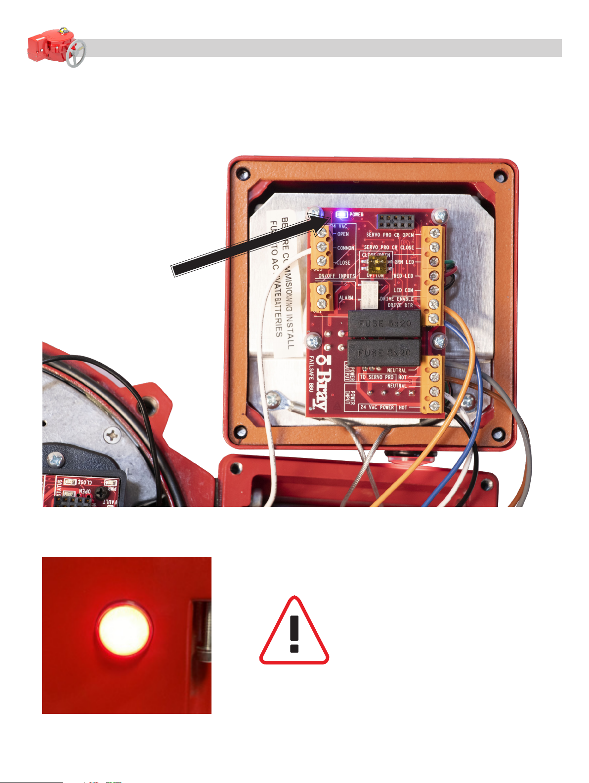
7.4 Insert the fuse supplied under the white label. See [Figure 13] below. Verify LED indicator on the
side of the BBU is flashing RED and the Power LED on the BBU Circuit Board is on.
Figure 13
WARNING – ONCE BATTERY POWER
IS APPLIED TO THE BBU, THE UNIT IS
OPERATIONAL AND MAY CAUSE THE
ACTUATOR TO SEEK THE FAIL POSITION
IF THE MAIN POWER IS NOT CONNECTED
TO THE BBU.

15
Battery Backup Unit (BBU) - Installation, Operation & Maintenance Manual Continued
7.5 Turn on the Power Supply to the BBU. Verify LED indicator on the side of the BBU is flashing or steady
GREEN, see [Figure 14] below. Electrically command the actuator full open and close to verify proper
actuator operation.
7.6 Command the actuator to the position opposite of the Fail Position. Turn off the Power Supply and verify
that the BBU drives the actuator to the full Fail Position and the LED indicator on the side of the BBU
is Rapidly flashing RED. After the actuator has reached full Fail Position, the LED indicator will Slowly
flash RED. See [Figure 15] for details.
Figure 14
Figure 15 Indication Description
Solid Green The BBU is powered and the
batteries are fully charged.
Flashing Green The BBU is powered and the
batteries are charging.
Fast Flashing Red The BBU is not powered and the
actuator is seeking the fail position.
Slow Flashing Red The BBU is not powered and the
BBU is in low power stand-by.

16
Battery Backup Unit (BBU) - Installation, Operation & Maintenance Manual Continued
8.0 Final Assembly
8.1 Reconnect the top and bottom BBU case assemblies. Be careful not to pinch or damage wiring and
ensure the BBU enclosure gasket is in place. [Figure 16]
8.2 If the actuator has already been calibrated then reinstall the actuator lid and the assembly is ready for use.
If the actuator is not calibrated or needs recalibration then procedure with a separate procedure S70 Quick
Start Guide, found on our Bray Commercial Division website and available upon request. [Figure 17]
Figure 16
Figure 17

17
Battery Backup Unit (BBU) - Installation, Operation & Maintenance Manual Continued
Battery Backup (BBU) - Wiring
24 VAC On/Off Controller BBU - Size 800-2,000 lb-in - (BCD-WD-A014-3)

18
Battery Backup Unit (BBU) - Installation, Operation & Maintenance Manual Continued
Battery Backup (BBU) - Wiring
On/Off NXT BBU - Size 5,000 lb-in - (BCD-WD-A034-3)

19
Battery Backup Unit (BBU) - Installation, Operation & Maintenance Manual Continued
Battery Backup (BBU) - Wiring
24 VAC Modulating NXT BBU - Size 800-5,000 lb-in - (BCD-WD-A035-2)
Other manuals for BBU
1
Table of contents
Popular UPS manuals by other brands


Powerware
Powerware 9335 Installation and operation manual

MGE UPS Systems
MGE UPS Systems PULSAR EVOLUTION 3000 XL Connection instructions

Cyber Power
Cyber Power OL6000ERT3UDM user manual

RS
RS PTM Series Installation instructions and owner's manual

Rockwell Automation
Rockwell Automation Allen-Bradley Bulletin 1609 installation instructions

Borri
Borri UPSaver 400 kVa operating manual


