BRECHTEL 3110 User manual
Instrument Manual
PRE-HUMIDIFIER 3110
83-00029-01
September 13, 2017

Pre-Humidifier 3110
Contents
1 Changes 2
2 Unpacking 3
3 Pre-Humidifier Overview 4
4 Installation 5
4.1 Power Connections .......................................... 5
4.2 Instrument Rack Mounts ....................................... 5
4.3 Compressed Air Connection ..................................... 5
4.4 Sample Flow Connections ...................................... 6
4.5 Humidification Control System ................................... 6
5 Pre-Humidifier Operation 7
5.1 Operation Overview ......................................... 7
6 Pre-Humidifier Specifications 8
7 Appendix 9
83-00029-01 Page 1 of 9

Pre-Humidifier 3110
1 Changes
Change Description Page Date Authorized By:
First Draft N/A 9/12/2017 FJB
83-00029-01 Page 2 of 9

Pre-Humidifier 3110
2 Unpacking
Each Brechtel Manufacturing Pre-Humidifier is inspected and tested in-house at Brechtel Manufacturing
to ensure out of the box operation upon delivery. Prior to opening, inspect the packaging container and
ShockWatch impact indicator.
Carefully open the package and inspect the instrument and accessories for broken parts, scratches, dents
or other signs of damage incurred during shipping.
Notify BMI within 2 days of receiving package if the shock indicator (Fig 1) has activated and/or of
any other visible damage
Verify the contents of the shipment with the unpacking instructions, which are enclosed inside the packaging
and available as a PDF file.
Retain all shipping packaging, foam inserts and cushions to ensure a safe delivery should the in-
strument need to be returned.
Figure 1: The black lines in the bottom image indicates the package has experiences an impact.
83-00029-01 Page 3 of 9

Pre-Humidifier 3110
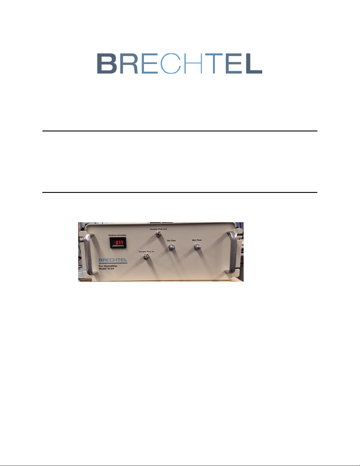
3 Pre-Humidifier Overview
The Brechtel Manufacturing Pre-Humidifier is a simple device designed to bring a particle sample flow to a
known relative humidity. The Pre-Humidifier can be implemented as a component of a suite of instruments,
in particular the Model 3100 HTDMA, to explore the humidity dependence of particle size, efflorescence,
deliquescence, and other properties. The unit is typically operated by controlling mixing dry and water sat-
urated air flows inside a small metal box containing 24 inches of nafion tubing. The sample flow is drawn
through the instrument by a user supplied vacuum and the RH of the flow near the sample exit can be read
using the display on the chassis front panel. By changing the ratio of wet and dry air flows, the RH of the
flow can be changed.
Figure 2: Front view of the Pre-Humidifier chassis.
The data from aerosol humidification studies are used to understand the air quality, climate and human
health impacts of aerosols. The unit can also be used in a routine air-monitoring mode at urban and remote
field sites to continuously measure the ambient aerosol efflorescence and deliquescence cycles as part of
the BMI HTDMA.
83-00029-01 Page 4 of 9

Pre-Humidifier 3110
4 Installation
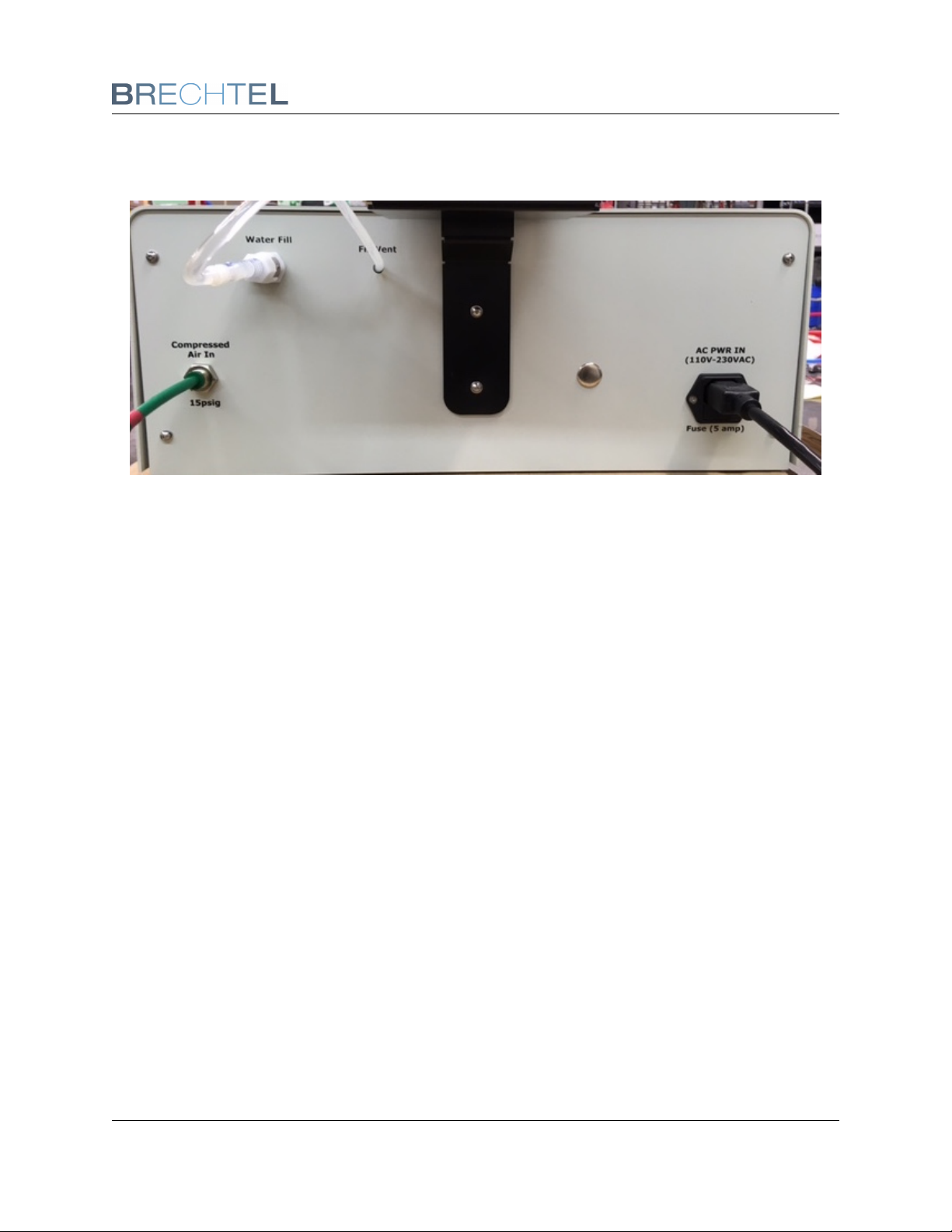
The Brechtel Manufacturing Pre-Humidifier is operational out of the box with only minimal additional assem-
bly. Attach the water bottle mounting bracket to the rear panel of the chassis and fill the water bottle with
distilled water. Insert the vent tube into the hole in the top of the water bottle to allow proper water filling.
Connect the water bottle supply tube to the ’Water Fill’ panel mount connector on the rear panel so water
flows into the chassis. The sections below describe how to configure the Pre-Humidifier for your specific
environment.
Figure 3: View of the Pre-Humidifier Water Fill Bottle mounted to rear panel of chassis.
4.1 Power Connections
Power is supplied to the back panel of the Pre-Humidifier from a 100-240VAC supply. The unit automatically
adjusts to the input AC voltage.
4.2 Instrument Rack Mounts
The Brechtel Manufacturing Pre-Humidifier is able to mount into a 19 inch instrument rack using the built-in
rackmount ears on each side of the chassis.
4.3 Compressed Air Connection
The push-lock fitting on the rear of the Pre-Humidifier and is used to supply clean compressed air at beteen
5 and 15 psig during operation. The fitting accepts 1/4” outside diameter tubing. The total air flow rate
83-00029-01 Page 5 of 9
Pre-Humidifier 3110
required varies depending on desired RH set points but typically is less than 5 lpm. A filter inside the
chassis removes particles from the compressed air flow before the needle valves.
Figure 4: Rear view of the Pre-Humidifier chassis.
4.4 Sample Flow Connections
The 1/4” sample inlet and outlet fittings are made from stainless steel. Connect to the inlet and outlet fittings
using electrically conductive tubing. The Pre-Humidifier is optimized to humidify sample flow rates less than
1 lpm, the higher the sample flow rate, the lower maximum RH that can be reached.
4.5 Humidification Control System
The RH control system is completely contained within the chassis and requires no user installation. Ensure
the water bottle is full so water is provided to the unit.
83-00029-01 Page 6 of 9

Pre-Humidifier 3110
5 Pre-Humidifier Operation
5.1 Operation Overview
Two manual needle valves are provided on the front panel to control the dry and wet air flow rates that
mix together to create the desired sample flow RH. The wet flow is created using a 36” long nafion tube
submerged in a water bath maintained at 40◦C . Dry compressed air enters the nafion tube in the water
bath and becomes saturated with water vapor.
When attempting high RH operation, be sure to tightly close the Dry Flow valve to limit the amount of dry
flow supplied to the sample humidifier.
The saturated air flow from the wet bath is mixed with a dry air flow and the mixed flow is delivered to a
second box housing another 24” coil of nafion. The particle sample flow is passed through the 24” long
nafion. By manually adjusting the ratio of dry and wet air flow rates, different RH values can be attained.
Because of the nature of the nafion tubing, the system is relatively slow response, be sure to wait several
minutes after making changes to the air flow rates to determine the change in RH. An RH sensor monitors
the RH of the sample flow just before the exit port on the front panel. The RH sensor reading is displayed
on the front panel.
Warning: Operating the Pre-Humidifier at RH above 80% over long periods of time (days) can possibly
result in water condensation inside the sample flow nafion box. To operate under dry conditions, dry air flow
may be required for a substantial amount of time to evaporate any liquid condensate.
Figure 5: Front view of the Pre-Humidifier chassis.
Connect your aerosol instrument to the sample flow out port of the Pre-Humidifier . In the case of the
Brechtel Model 3100 HTDMA, the Pre-Humidifier is installed between the SEMS and HSEMS so that the
dry monodisperse flow from the SEMS, after the MCPC flow splitter, is attached to the Pre-Humidifier
sample flow in port. The sample flow out port of the Pre-Humidifier is connected to the HSEMS sample
flow in port. The RH setting of the Pre-Humidifier can be manually entered into the HSEMS AutoScheduler
software. Adding the Pre-Humidifier to the HTDMA allows particle efflorescence studies to be conducted by
exposing the dry SEMS-selected particles to a high RH in the Pre-Humidifier and then exposing the sample
flow to a lower RH in the HSEMS.
83-00029-01 Page 7 of 9

Pre-Humidifier 3110
6 Pre-Humidifier Specifications
Relative Humidity
Description MIN MAX UNIT
Sample Flow 0.1 2.0 lpm
RH 20 90 %
Response Time 1 10 minutes
Power
Description MIN MAX UNIT
Voltage Input 100 240 VAC
Power Input 10 Watts
Physical Dimensions
Description MIN UNIT
Width 19 in
Depth 12 in
Height 7 in
Weight 19 lb
83-00029-01 Page 8 of 9

Pre-Humidifier 3110
7 Appendix
83-00029-01 Page 9 of 9
Table of contents


