1
CONTENTS
1 GENERAL
1.1 How to use this Manual .......................................................................... 2
1.2 Service and Support ............................................................................... 2
1.3 Used Products and the Environment ...................................................... 3
1.4 Symbols .................................................................................................. 3
1.5 Intended Use and Remarks on Safety .................................................... 3
1.6 Warranty Conditions ............................................................................... 4
2 DESCRIPTION
3 INSTALLATION
3.1 Unpacking and Inspection ...................................................................... 6
3.2 Installation ............................................................................................... 6
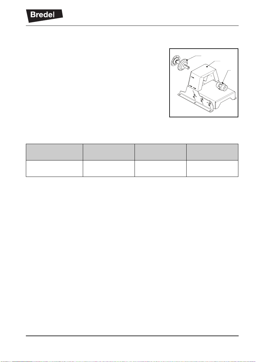
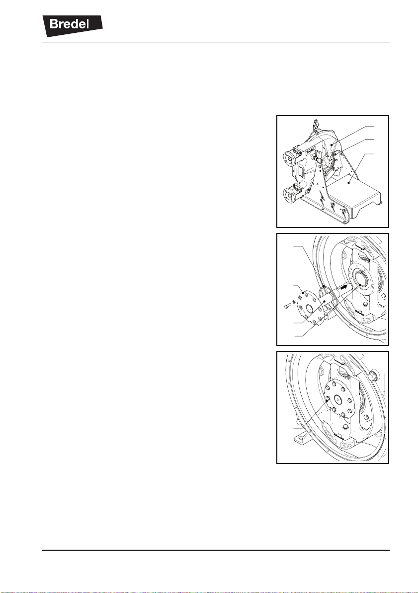
3.2.1 Mounting the support set and the bare shaft kit to
the pumphead ............................................................................. 7
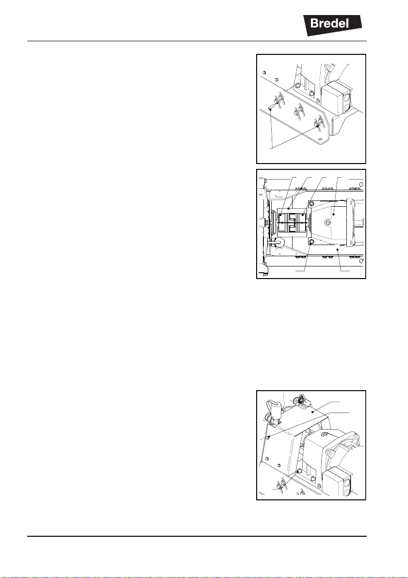
3.2.2 Mounting and aligning the Drive ................................................ 10
4 MAINTENANCE
4.1 Cleaning ................................................................................................ 13
4.2 Demounting the pumphead .................................................................. 13
4.3 Demounting the drive ............................................................................ 14
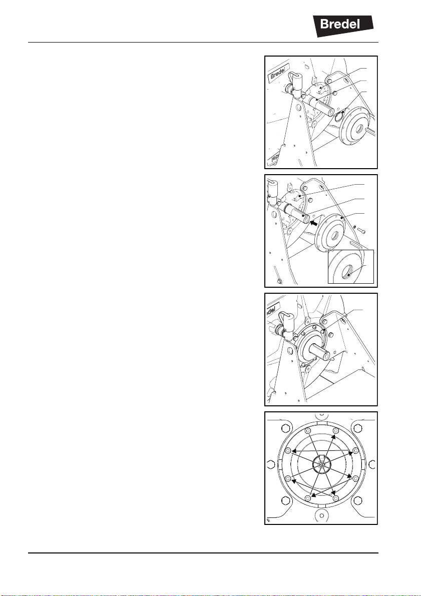
4.4 Demounting the bare shaft hub ............................................................ 15
4.5 Disassembling the bare shaft hub ........................................................ 16
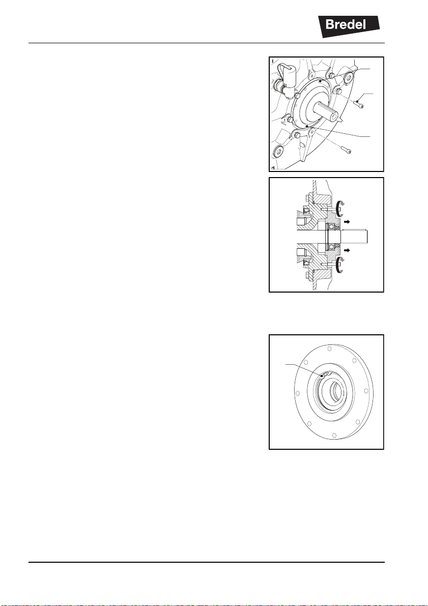
4.6 Assembling the bare shaft hub ............................................................. 17
4.7 Mounting the bare shaft hub onto the pump ......................................... 19
4.8 Mounting the Drive ................................................................................ 20
4.9 Mounting the pumphead ....................................................................... 22
5 TROUBLESHOOTING
6 SPECIFICATIONS
6.1 Bredel 40 bare shaft set ........................................................................ 26
6.1.1 Support set ................................................................................ 26
6.1.2 Bare Shaft Kit ............................................................................ 27
6.2 Weights ................................................................................................. 28
6.3 Torque .................................................................................................. 28
6.4 Coupling ................................................................................................ 28
SAFETY FORM