Bredel APEX 10 User manual
Copyright © 2016 Watson-Marlow Fluid Technology Group 28-1003208
DuCoNite® and Watson-Marlow Bredel
are registered trademarks.
APEX / BREDEL PUMP
Additional information on APEX and Bredel 10, 15 and 20 pumps with bare shaft
configuration

Additional information on APEX and Bredel
10, 15 and 20 pumps with bare shaft configuration
Original Instructions

© 2017 Watson-Marlow Bredel B.V.
All rights reserved.
The information provided herein may not be reproduced and/or published in any form,
by print, photoprint, microfilm or any other means whatsoever (electronically or
mechanically) without the prior written authorisation of Watson-Marlow Bredel B.V.
The information provided can be changed without prior notification. Watson-Marlow
Bredel B.V. or one of its representatives cannot be held liable for possible damage
resulting from use of this manual. This is an extensive limitation of the liability which
applies to all damage, inclusive of (without limitation) compensating, direct, indirect or
consequential damage, loss of data, income or profit, loss or damage to possessions
and claims of third parties.
Watson-Marlow Bredel B.V. provides the information in this manual "as is" and does not
take any responsibility and does not give any guarantee on this manual or its content.
Watson-Marlow Bredel B.V. rejects all responsibilities and guarantees. Furthermore,
Watson-Marlow Bredel B.V. does not take responsibility for and does not guarantee that
the information in this manual is accurate, complete or up to date.
Names, trade names, brands, etc. used by Watson-Marlow Bredel B.V. may not, as per
the legislation concerning the protection of trade names, be considered as available.

1
CONTENTS
1 GENERAL
1.1 How to use this Manual .......................................................................... 2
1.2 Service and Support ............................................................................... 2
1.3 Used Products and the Environment ...................................................... 3
1.4 Symbols .................................................................................................. 3
1.5 Intended Use and Remarks on Safety .................................................... 3
1.6 Warranty Conditions ............................................................................... 4
2 DESCRIPTION
3 INSTALLATION
3.1 Unpacking and Inspection ...................................................................... 6
3.2 Installation .............................................................................................. 6
3.2.1 Mounting the support set and Bare Shaft Kit ............................... 7
3.2.2 Mounting and aligning the Drive .................................................. 9
4 MAINTENANCE
4.1 Cleaning ................................................................................................ 12
4.2 Demounting the Drive ........................................................................... 12
4.3 Demounting the Bare Shaft Kit ............................................................. 13
4.4 Disassembling the Bare Shaft Kit ......................................................... 14
4.5 Assembling the Bare Shaft Kit .............................................................. 15
4.6 Mounting the Bare Shaft Kit onto the Pump ......................................... 17
4.7 Mounting the Drive ................................................................................ 18
5 TROUBLESHOOTING
6 SPECIFICATIONS
6.1 Parts list ................................................................................................ 22
6.1.1 Support Set 10-20 ..................................................................... 22
6.1.2 Bare Shaft Kit ............................................................................ 23
6.2 Weights ................................................................................................. 23
6.3 Torque .................................................................................................. 24
6.4 Coupling ................................................................................................ 24
SAFETY FORM

GENERAL
2
1 GENERAL
1.1 How to use this Manual
This manual is intended as a reference book for
qualified users, enabling them to install, commission
and maintain the bare shaft set as mentioned on the
front cover. This manual is an addition to the pumphead
manual, drive manual and gearbox manual. This
manual does not replace any of these documents. The
user should carefully read these documents before
using this manual.
Documentation of components such as pumps, motors
and inverters is normally not included in this manual.
However, if additional documentation is supplied, you
must follow the instructions in this additional
documentation.
1.2 Service and Support
For information with respect to specific adjustments,
installation, maintenance or repair jobs which fall
beyond the scope of this manual, contact your Bredel
representative. Make sure you have the following data
at hand:
•
Type and / or serial number of the hose pump.
•
Description of the drive or gearbox.
You will find these data on the identification plates or
stickers of the pumphead and the drive or gearbox.

GENERAL
3
1.3 Used Products and the Environment
Enquire with your local government about the
possibilities for reuse or environment friendly
processing of packaging materials, (contaminated)
lubricant and oil.
1.4 Symbols
In this manual the following symbols are used:
1.5 Intended Use and Remarks on Safety
The bare shaft set is exclusively designed for
supporting a Bredel or an APEX pumphead and a drive.
Every other use is not in conformance with the intended
ENVIRONMENT
Always observe the local rules and
regulations with respect to processing
(nonreusable) parts of the hose pump.
WARNING
Procedures which, if not carried out with
the necessary care, may result in serious
bodily harm.
CAUTION
Procedures which, if not carried out with
the necessary care, may result in serious
damage to the hose pump, the surrounding
area or the environment.
Remarks, suggestions and advice.

GENERAL
4
use. Refer to the manual of the pumphead for more
information on safety and the intended use of the
complete pump.
1.6 Warranty Conditions
Refer to the manual of the pumphead for warranty
conditions. These conditions are applicable to the bare
shaft set as well. Damaged parts of the bare shaft set
that are returned to the manufacturer must be
accompanied by a fully filled in and signed safety form
that can be found in the manual of the pumphead.

DESCRIPTION
5
2 DESCRIPTION
The bare shaft set, if delivered separately, consists of a
support set (A) and a bare shaft kit (B). These two
components are packed separately. If the set is
delivered in a complete pump with pumphead and drive
a flexible coupling (C) is included.
The support set consists of a frame, an adjustable drive
support plate and a coupling guard.
The bare shaft kit consists of a shaft, a hub, a bearing
and a seal. No fasteners are provided for mounting the
drive or gearbox.
To align the pump and the drive use alignment jigs. The
jigs are not included in the package.
B
C
A
Although the instructions in this manual are
demonstrated with the Bredel 10-20 pump
series, these are also applicable to the
APEX10-20 series.
INSTALLATION
6
3 INSTALLATION
3.1 Unpacking and Inspection
Follow the unpacking instructions on the packaging.
Check that your delivery is correct and does not have
transport damage. Report any damage immediately to
your Bredel representative.
This chapter describes the installation of the bare shaft
set. Refer to the manual of the pumphead for
installation and setup of the complete pump and the
pipework.
3.2 Installation
CAUTION
The drive or gearbox and the pump must
be aligned within the misalignment limits of
the flexible coupling.
Carry out the alignment of the drive or
gearbox and the pump at the pump’s final
operating position. If the support set has to
be bolted to the floor this must be done
first.
A movement of the complete pump can
disturb the alignment due to elasticity of
the construction.
If the bare shaft set is delivered as part of a
complete pump, including pumphead and
drive, a realignment must be done at the
pump’s final operating position.

INSTALLATION
7
3.2.1 Mounting the support set and Bare Shaft Kit
For mounting the kit to the pumphead, the pump must
not be part of a process line and must be free of
lubricant.
1. Place the bare shaft kit (A) on a flat surface with
the key end upward.
Press coupling half (B) onto the shaft end until
shaft end face (C) and coupling surface (D) are
at equal level.
Slightly fasten screw (E).
Prevent unnecessary axial load on the bearing.
Alternative method of pressing the coupling half
onto the shaft end is using a threaded rod
screwed into the threaded hole in the shaft end,
a disc with hole and a nut. Turning the nut will
drive the coupling half onto the shaft.
This way the coupling half can be mounted after
the placement of the bare shaft kit on the
pumphead.
2. Use a hoist to place the pumphead with the
cover side on blocks.
D
B
C
A
E
INSTALLATION
8
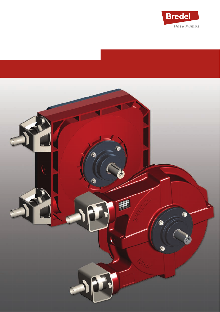
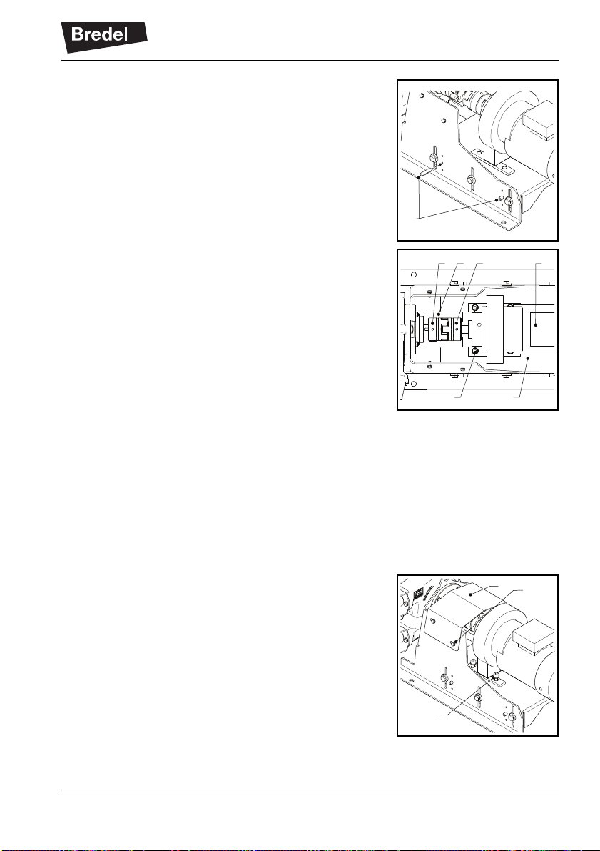
3. Remove the coupling guard from the support
set.
Use a hoist to place the support set on the rear
of the pumphead.
4. Place the bare shaft kit (A) with the 3-teeth
coupling end into the pump.
Make sure the 3 teeth correctly mesh with the
holes in the rotor inside the pump.
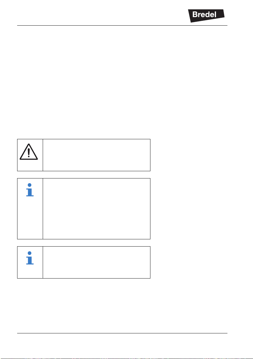
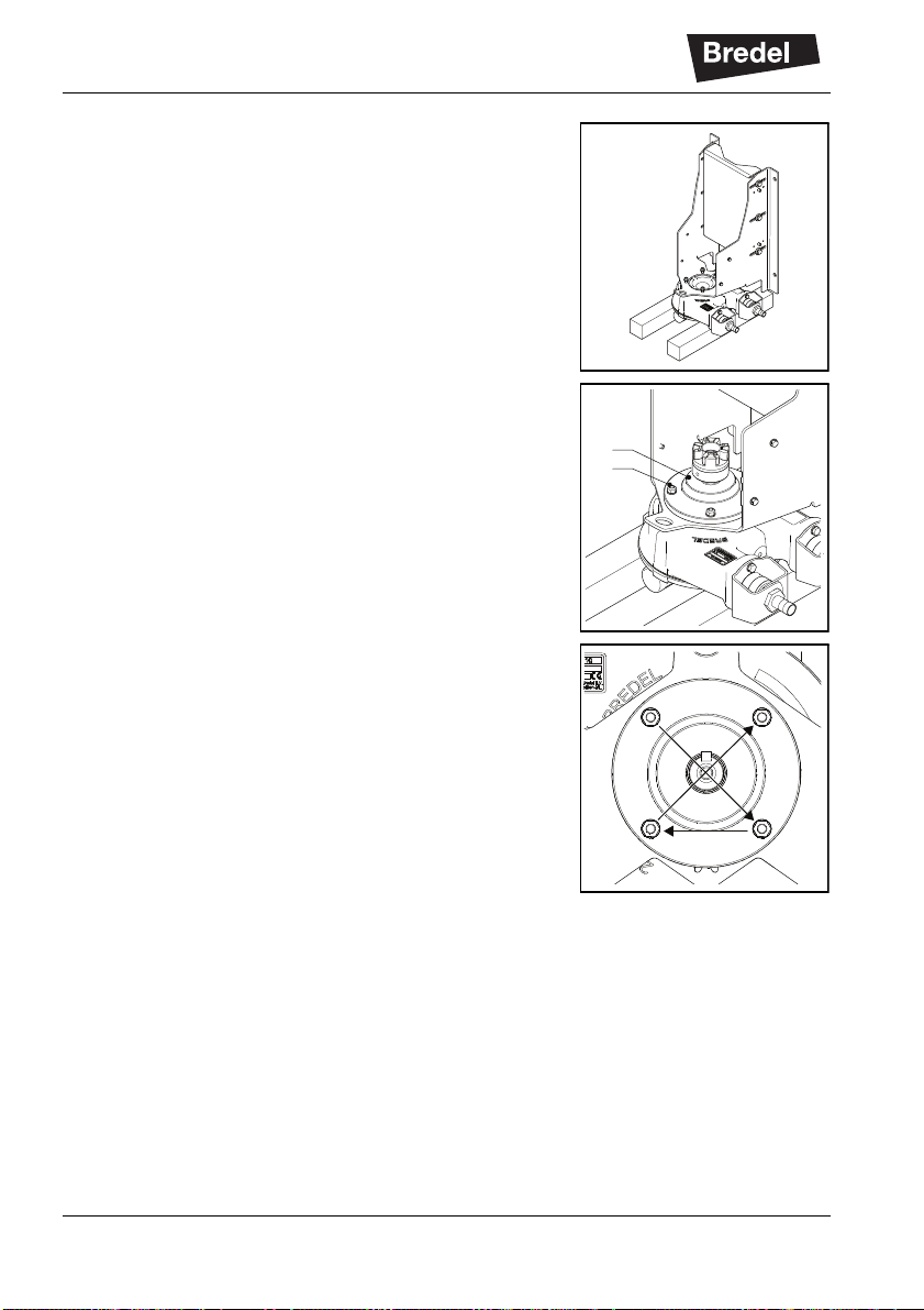
5. Place washers and nuts (B).
6. Tighten the nuts in at least two crosswise
cycles. In the last cycle tighten them with the
correct torque. See section 6.3.
7. Use a hoist to turn the pumphead with support
set to the horizontal position.
A
B
11
3
3
4
22
4
INSTALLATION
9
3.2.2 Mounting and aligning the Drive
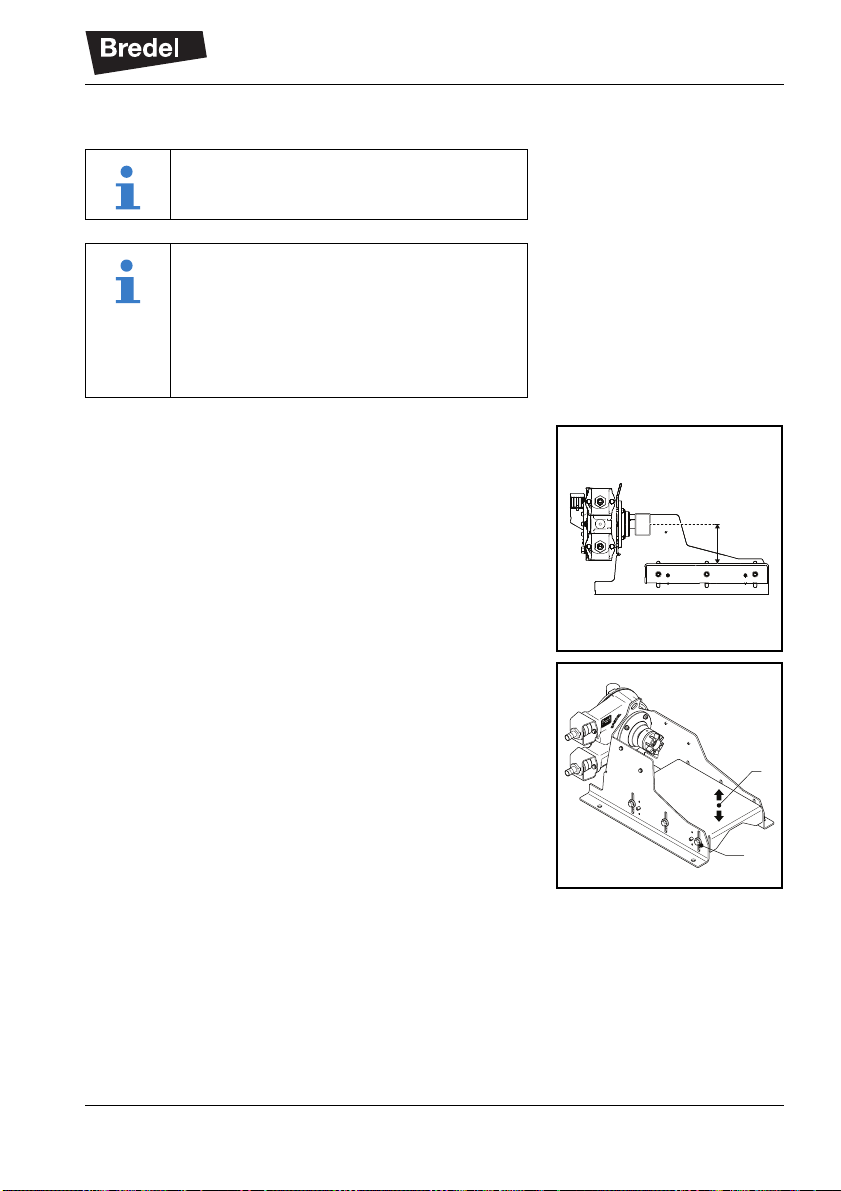
1. Determine the correct height (H) of the centre of
the bare shaft according to the surface on which
the drive will be mounted. The bare shaft height
must correspond with the height of the output
shaft centre of the drive that will be mounted.
2. To correct the height loosen the six sets of
fasteners (A).
Move the plate (B) up or down to the correct
position and slightly tighten the fasteners (A).
Check the height and repeat this step if
necessary.
If the height is correct, tighten the fasteners (A)
with the correct torque. See section 6.3.
Use a hoist to lift the drive.
Mounting and aligning the drive must be
done on the pump’s final operation
position. Moving the complete pump
assembly after alignment will require re-
alignment at the pump’s final operation
position.
H
A
B

INSTALLATION
10
3. Place coupling half (A) on the output shaft of the
drive and slightly fasten screw (B).
Make sure the shaft end has been shifted far
enough into the coupling half but will not
penetrate into the coupling spider (C).
4. Use a hoist to place the drive on the support
set.
5. Make sure spider is placed in one of the
coupling halves.
6. Slide the drive toward the pumphead.
Make sure that the coupling halves (A) and the
spider mesh correctly.
7. Use two alignment jigs (D) to check the
alignment of the coupling halves in the vertical
plane. Looking from aside both coupling halves
(C) must touch the horizontal edge of the upper
jig.
If necessary loosen the fasteners (A), readjust
the plate (B) and fasten the fasteners (A) to
accomplish this. Use a hoist to lift the drive.
Axial, radial and angular displacement of the
coupling halves must be minimised. See section
6.4.
8. Each side plate of the support set has 2 sets of
3 holes (A). Determine if the upper, the middle
or the lower hole is most suitable to be drilled
through into the side wall of plate (B).
Use a drill of 8mm to drill this hole through both
plates.
AB
C
A
B A
C D C
AB
INSTALLATION
11
9. Drive a pin (A) into each drilled hole to fix the
horizontal plate in the support set side plates.
10. Use two alignment jigs (D) to check the
alignment of the coupling halves in the
horizontal plane. Looking from above both
coupling halves (C) must touch the edge of both
jigs.
If necessary move the drive (E) over the plate
(A) to accomplish this.
Axial, radial and angular displacement of the
coupling halves must be minimised.
11. Mark the holes (B) for fixing the drive on the
plate of the support set using a punch and a
hammer, or a felt-tip pen.
12. Remove the alignment jigs and use a hoist to
remove the drive.
13. Drill holes, with the correct diameter, in the
horizontal plate (A) at the marked places. See
section 6.3.
14. Remount the drive and slide it toward the
pumphead so that the coupling halves mesh.
15. Fix the drive to the horizontal plate with
fasteners (A) (washers, bolts or screws, and
nuts). Do not tighten the fasteners yet.
16. Repeat step 10. (alignment in a horizontal
plane)
Tighten the fasteners (A) and the screws of the
coupling halves with the correct torque. See
section 6.3.
17. Place the coupling guard (B).
Tighten the fasteners (C) with the correct
torque. See section 6.3.
A
C D
BA
C E
C
A
B

MAINTENANCE
12
4 MAINTENANCE
4.1 Cleaning
4.2 Demounting the Drive
1. Isolate the drive from the electrical supply.
2. Loosen the fasteners (C) of the coupling guard
and remove the coupling guard (B).
3. Loosen and remove the fasteners (A).
4. Move the drive (A) backward to separate the
coupling halves (B and C).
Use a hoist to remove and set aside the drive.
WARNING
When cleaning the pump do not use a
high-pressure spraying pistol. This might
damage the seal and the bearing.
Use a hoist to lift the drive.
C
A
B
BCA
MAINTENANCE
13
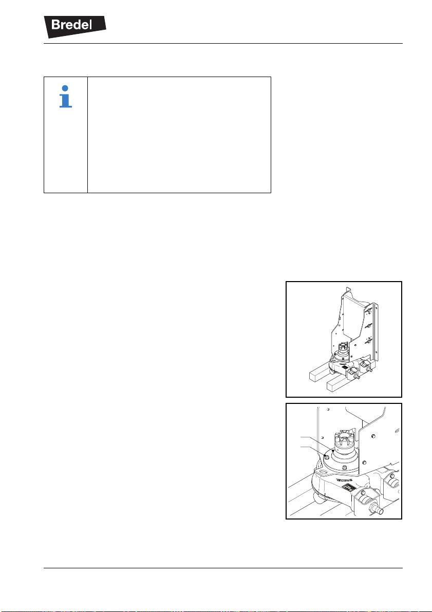
4.3 Demounting the Bare Shaft Kit
1. Close any shut-off valves in the suction and
discharge lines and disconnect these lines.
Refer to the manual of the pump.
2. Remove the lubricant from the pumphead.
Refer to the manual of the pump.
3. Use a hoist to turn over the pump and put it on
blocks.
4. Demount the bare shaft kit (A) by loosening
fasteners (B).
When the bare shaft kit is demounted the
pumphead will come loose from the
support set. The pumphead must be
supported in some way, or the pumphead
has to be tipped to the front. In the latter
case piping has to be disconnected and
lubricant has to be removed first.
In this manual it is assumed that the
pumphead will be tipped to the front.
A
B
MAINTENANCE
14
4.4 Disassembling the Bare Shaft Kit
1. Remove coupling half (B) from the shaft by
loosening screw (A). Use a suitable pulling
device.
Do not put axial load on the bearing if it is to be
reused.
2. Remove retaining ring (A).
3. Remove key (B).
4. Push shaft (A) out of hub (B). Use a suitable
pulling device.
B
A
B
A
A
B
MAINTENANCE
15
5. Remove bearing (B) from shaft (A). Use a
suitable pulling device.
6. Remove seal (A) from hub (B). If the seal is to
be replaced pliers can be used.
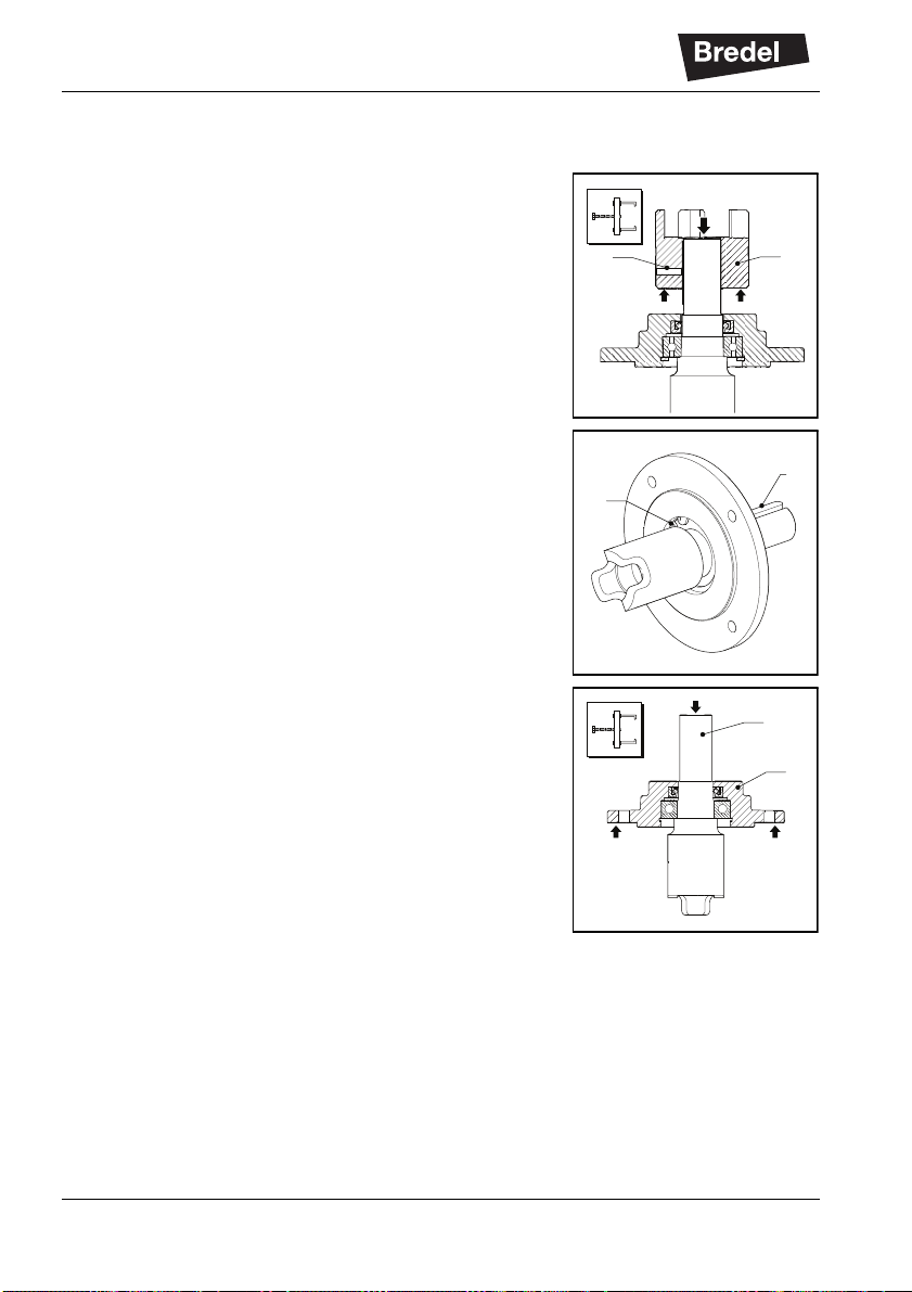
4.5 Assembling the Bare Shaft Kit
Check the bearing and the seal before reuse. If
necessary use a new bearing and a new seal.
1. Place the hub (B) on a flat surface, with the
bearing side upward. Clean the contact
surfaces (A) for bearing and seal and put some
transmission oil on these surfaces.
A
B
B
A
B
A

MAINTENANCE
16
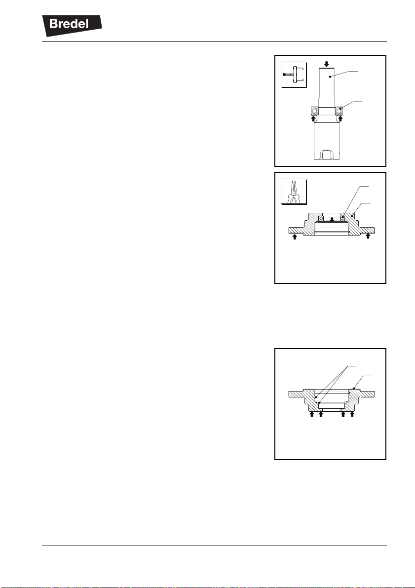
2. Use a suitable tool (A) to press seal (B) into the
hub until it hits the collar. Keep the closed side
of the seal upward.
3. Put an excessive amount of grease on the lip of
the seal.
4. Clean the contact surfaces (A) for bearing and
seal on the shaft (B). Put some grease on these
surfaces.
5. Place shaft (C) on a flat surface with the key
end upward. Press bearing (B) on the shaft with
a suitable tool (A) until it touches the rim.
6. Place the hub (C), with the bearing side upward,
on a flat surface with a hole.
Place shaft (D), with the key end pointing down,
into the hub (C).
Press bearing (B), with a suitable tool (A), into
the hub until it touches the bearing rim.
BA
B
A
A
B
C
A
B
C
D

MAINTENANCE
17
7. Place key (B) onto the shaft.
8. Place retaining ring (A) into the hub.
9. Mount a coupling half on the shaft end. See
section 3.2.1 step 1.
4.6 Mounting the Bare Shaft Kit onto the Pump
For this procedure the pumphead should still be placed
on blocks with the support set resting on the
pumphead´s rear side. One coupling half is still
mounted on the drive shaft end.
If necessary apply a new spider for the flexible coupling.
1. Place the bare shaft kit (A) with the 3-teeth
coupling end into the pump and assure that the
teeth correctly mesh with the holes in the rotor
inside the pump.
2. Place washers and nuts (B).
3. Tighten the nuts in at least two crosswise
cycles. In the last cycle tighten them with the
correct torque. See section 6.3.
4. Use a hoist to turn the pumphead with support
set to horizontal position.
5. Fill the pumphead with lubricant. Refer to the
manual of the pump.
6. Connect the suction and discharge lines and
open any shut-off valves in these lines. Refer to
the manual of the pump.
B
A
A
B
11
3
3
4
22
4
This manual suits for next models
2
Table of contents
Other Bredel Water Pump manuals


Popular Water Pump manuals by other brands


Pentair
Pentair Shurflo 358 Installation and operation manual

Fountain TECH
Fountain TECH FT-1900 user guide

Grundfos
Grundfos ALPHA1 L Series Installation and operating instructions

Viking pump
Viking pump 4223AX Series Technical & service manual

Edwards
Edwards E2M28 instruction manual

BATHMATE
BATHMATE HYDROVIBE user guide


