Bren-Tronics BTE-70791A-T1B User manual

BREN-TRONICS, INC
P: 631-499-5155 | F: 631-499-5504
www.bren-tronics.com
850069 Rev M
BTE-70791A-T1BR (CE, UKCA)
OPERATION MANUAL
BTE-70791A-T1B / BTE-70791A-G1B
BTE-70791A-T1BR / BTE-70191A-G1BR
BTE-70791A-T1BR2 / BTE-70191A-G1BR2
NSN: 6130-01-588-5188
Copyright © Bren-Tronics, Inc. 2022
BTE-70791A-T1B (Shown)
BTE-70791A-T1BR2 (CE, UKCA)

BREN-TRONICS, INC
10 Brayton Court
Commack, NY 11725
P: 631-499-5155 | F: 631-499-5504
www.bren-tronics.com
Page 2of 25
BTE-70791A-T1B / BTE-70791A-T1BR / BTE-70791A-T1BR2
PORTABLE POWER SYSTEM (6-PACK)
OPERATION MANUAL
850069 REV M
Data presented in this document is subject to change without notice.
WARNING
HIGH VOLTAGES ARE PRESENT IN THE
OPERATION OF THIS EQUIPMENT
Avoid contact with AC supply voltage connections during installation,
operation and/or maintenance.
CAUTION
To prevent electric shock, make sure that pin E of the AC input is connected to
the ground (earth) of the utility power mains when using AC power!
Other CAUTIONS pertaining to the equipment output are located in the
INTERFACE WIRING section.
Input-power and output ratings are located in the INTERFACE WIRING section.
NOTICE TO PERSONS RECEIVING THIS DRAWING
AND/OR TECHNICAL INFORMATION:
BREN-TRONICS, INC. claims proprietary rights in the material disclosed
herein. This drawing and/or technical information is issued in confidence
for information only and may not be reproduced or used to manufacture
anything shown or referred to heron without direct permission from BREN-
TRONICS INC. to the user. This drawing and/or technical information is
loaned for mutual assurance and is subject to recall by BREN-TRONICS
INC. at any time.
This drawing and/or technical information
is the property of BREN-TRONICS, INC.

BREN-TRONICS, INC
10 Brayton Court
Commack, NY 11725
P: 631-499-5155 | F: 631-499-5504
www.bren-tronics.com
Page 3of 25
BTE-70791A-T1B / BTE-70791A-T1BR / BTE-70791A-T1BR2
PORTABLE POWER SYSTEM (6-PACK)
OPERATION MANUAL
850069 REV M
Data presented in this document is subject to change without notice.
6-PACK OPERATION MANUAL
Table of Contents
1BASIC CONFIGURATION..................................................................................4
2TECHNICAL SPECIFICATIONS.........................................................................5
3DECLARATION OF CONFORMITY...................................................................6
4ACCESSORIES................................................................................................10
4-1 INPUT CABLES.......................................................................................10
4-2 OUTPUT CABLES...................................................................................11
4-3 OPTIONAL EQUIPMENT........................................................................12
5THE BATTERIES..............................................................................................13
6INTERFACE WIRING.......................................................................................15
6-1 OUTPUT CONNECTOR..........................................................................15
6-1-1 BTE-70791A-T1B, -T1BR2......................................................................15
6-1-2 BTE-70791A-T1BR.................................................................................15
6-2 INPUT CONNECTORS ...........................................................................17
6-2-1 DC INPUT............................................................................................17
6-2-2 AC INPUT ............................................................................................17
7CONTROLS......................................................................................................17
8INDICATORS....................................................................................................18
8-1 LCD DISPLAYS.......................................................................................18
8-2 LED INDICATORS ..................................................................................19
9POWER INPUT PRIORITY...............................................................................19
10 PROTECTIVE DEVICES..................................................................................20
11 OPERATOR MAINTENANCE INSTRUCTIONS...............................................20
11-1 CLEANING..............................................................................................20
11-2 WARRANTY / REPAIR INFORMATION..................................................21
APPENDIX A: COMMUNICATIONS INTERFACE..................................................22
APPENDIX B: NOMINAL CHARGE TIMES / APPLICATION DATA FOR UPS
USAGE....................................................................................................................24

BREN-TRONICS, INC
10 Brayton Court
Commack, NY 11725
P: 631-499-5155 | F: 631-499-5504
www.bren-tronics.com
Page 4of 25
BTE-70791A-T1B / BTE-70791A-T1BR / BTE-70791A-T1BR2
PORTABLE POWER SYSTEM (6-PACK)
OPERATION MANUAL
850069 REV M
Data presented in this document is subject to change without notice.
1BASIC CONFIGURATION
The 6-PACK consists of two electrically-independent battery banks; each bank can
hold one to three Bren-Tronics BB-2590/U lithium-ion batteries to form a high-
capacity, 14.4Vdc (nominal) battery bank. The two banks can be connected in
series or parallel, to provide a nominal output of 28.8Vdc or 14.4Vdc with a total
energy-storage capacity of 1.2kWh or higher (depending on which capacity version
of the BB-2590/U is used) with the potential to grow as higher-capacity versions of
the BB-2590/U become available.
Number
of
BB-
2590/U
batteries
installed:
Nominal capacity of 6-PACK
(Ah, series/parallel)
-
BT-
70791A
BT-
70791BK
BT-
70791BE
BT-
70791BG
BT-
70791CK
BT-
70791CE
BT-
70791CG
BT-
70791CK
BT-
70791JV
2 (one
per bank)
13.6/27.2
15.0/30.0
17.4/34.8
19.8/39.6
15.0/30.0
17.4/34.8
19.8/39.6
15.0/30.0
20.6/41.2
4 (two
per bank)
27.2/54.4
30.0/60.0
34.8/69.6
39.6/79.2
30.0/60.0
34.8/69.6
39.6/79.2
30.0/60.0
41.2/82.4
6 (three
per bank)
40.8/81.6
45.0/90.0
52.2/104.4
59.4/118.8
45.0/90.0
52.2/104.4
59.4/118.8
45.0/90.0
61.8/123.6
Numbe
r of
BB-
2590/U
batterie
s
installe
d:
Nominal capacity of 6-PACK (Wh)
-
BT-
70791
A
BT-
70791B
K
BT-
70791B
E
BT-
70791B
G
BT-
70791C
K
BT-
70791C
E
BT-
70791C
G
BT-
70791C
K
BT-
70791J
V
2 (one
per
bank)
400
450
500
588
450
500
588
450
604
4 (two
per
bank)
800
900
1000
1176
900
1000
1176
900
1208
6 (three
per
bank)
1200
1350
1500
1764
1350
1500
1764
1350
1812
Each bank is equipped with a communication interface that emulates “SMBus”
smart-battery operation via a RS-485 serial link.
Each bank also has its own microcontroller-based charger, which operates
independently to assure proper charging of all the installed batteries. These

BREN-TRONICS, INC
10 Brayton Court
Commack, NY 11725
P: 631-499-5155 | F: 631-499-5504
www.bren-tronics.com
Page 5of 25
BTE-70791A-T1B / BTE-70791A-T1BR / BTE-70791A-T1BR2
PORTABLE POWER SYSTEM (6-PACK)
OPERATION MANUAL
850069 REV M
Data presented in this document is subject to change without notice.
chargers can be powered from 24V “NATO” vehicular DC power, 12V automotive
DC power, 115V/230V utility AC power, or from solar panels (or other alternative
power sources).
Mechanically, the 6-PACK consists of a lower enclosure that holds the batteries for
both banks, and an upper enclosure that houses the chargers, battery monitors,
connectors, and controls.
2TECHNICAL SPECIFICATIONS
Dimensions………………..12.8 in. (325 mm) W x 10.8 in. (274 mm) D x 11.3 in.
(287 mm) H
Weight……………………..39.0 lbs (18.0 kg) with six (6) BB-2590/U batteries
20.0 lbs (9.5 kg) without batteries
Power Requirements
AC operation………Automatic selection: 90-264Vac, 250 VA
DC operation………11-18Vdc, 20A; 20-33Vdc, 15A;12-36Vdc Solar, 20A
Duty Cycle………………… Continuous
Operating Temp. Range….-4oF (-20oC) to +122oF (+50oC)
Storage Temp. Range……-40oF (-40oC) to +158oF (+70oC)
Loose Cargo Bounce……..Meets requirements of MIL-STD-810G, Method 514.6,
Procedure II
Enclosure Rating………….IP67 (1 meter/1 hour water immersion)
Input and Output Ratings...See Interface Wiring (section 5)
Case Material…………….. Heavy Duty Aluminum
Case Color………………... Tan or NATO Green
Shipment………………….. No restrictions
BREN-TRONICS, INC
10 Brayton Court
Commack, NY 11725
P: 631-499-5155 | F: 631-499-5504
www.bren-tronics.com
Page 6of 25
BTE-70791A-T1B / BTE-70791A-T1BR / BTE-70791A-T1BR2
PORTABLE POWER SYSTEM (6-PACK)
OPERATION MANUAL
850069 REV M
Data presented in this document is subject to change without notice.
3DECLARATION OF CONFORMITY

BREN-TRONICS, INC
10 Brayton Court
Commack, NY 11725
P: 631-499-5155 | F: 631-499-5504
www.bren-tronics.com
Page 7of 25
BTE-70791A-T1B / BTE-70791A-T1BR / BTE-70791A-T1BR2
PORTABLE POWER SYSTEM (6-PACK)
OPERATION MANUAL
850069 REV M
Data presented in this document is subject to change without notice.

BREN-TRONICS, INC
10 Brayton Court
Commack, NY 11725
P: 631-499-5155 | F: 631-499-5504
www.bren-tronics.com
Page 8of 25
BTE-70791A-T1B / BTE-70791A-T1BR / BTE-70791A-T1BR2
PORTABLE POWER SYSTEM (6-PACK)
OPERATION MANUAL
850069 REV M
Data presented in this document is subject to change without notice.

BREN-TRONICS, INC
10 Brayton Court
Commack, NY 11725
P: 631-499-5155 | F: 631-499-5504
www.bren-tronics.com
Page 9of 25
BTE-70791A-T1B / BTE-70791A-T1BR / BTE-70791A-T1BR2
PORTABLE POWER SYSTEM (6-PACK)
OPERATION MANUAL
850069 REV M
Data presented in this document is subject to change without notice.

BREN-TRONICS, INC
10 Brayton Court
Commack, NY 11725
P: 631-499-5155 | F: 631-499-5504
www.bren-tronics.com
Page 10 of 25
BTE-70791A-T1B / BTE-70791A-T1BR / BTE-70791A-T1BR2
PORTABLE POWER SYSTEM (6-PACK)
OPERATION MANUAL
850069 REV M
Data presented in this document is subject to change without notice.
4
ACCESSORIES
4-1 INPUT CABLES TABLE 1
DESCRIPTION
PART NUMBER
RoHS
DC CABLE SPLITTER
BTA-70816B
24V DC HUMMER CABLE
BTA-70835B
12V DC POWER CABLE (Alligator Clips)
BTA-70856-12AL
DC CIG LIGHTER CONNECTOR
BTA-70856-12C
12V DC POWER CABLE (Ring Lugs)
BTA-70856-1B
12V DC POWER CABLE (Ring Lugs), RoHS
BTA-70856-1BR
SOLAR POWER CABLE
BTA-70857-2B
SOLAR POWER CABLE, RoHS
BTA-70857-2BR
24V DC POWER CABLE (Ring Lugs)
BTA-70863-24
24V DC POWER CABLE (Ring Lugs), 10 m
BTA-70863-24-
10
24V DC POWER CABLE (Alligator Clips)
BTA-70863-24AL
DC POWER CABLE (Ring Term), RoHS
BTA-70863-24R
12V/24V DC POWER CONNECTOR
BTA-70863-C
12V/24V DC POWER CONNECTOR, RoHS
BTA-70863-CR
DC POWER EXTENSION CABLE
BTA-70863-EX
AC POWER CORD, US
BTA-70864-2
AC CABLE ASSY, US, RoHS
BTA-70864-2R
AC POWER CORD, US 6 ft.
BTA-70864-3
AC POWER CORD, EU
BTA-70864-5
AC CABLE, ASSY, EU, RoHS
BTA-70864-5R
AC POWER CORD, UK
BTA-70864-6
AC POWER CORD, UK, 10 m
BTA-70864-6-10
AC POWER CORD, US, DUAL
BTA-70864-7
AC POWER CORD, AUS/NZ
BTA-70864-8
AC POWER CORD, IT/CHILE
BTA-70864-9
AC POWER CONNECTOR
BTA-70864-C
AC POWER CONNECTOR (No Cable),
ROHS
BTA-70864-CR
All Input Power Cables are compatible with all 6-PACK configurations.

BREN-TRONICS, INC
10 Brayton Court
Commack, NY 11725
P: 631-499-5155 | F: 631-499-5504
www.bren-tronics.com
Page 11 of 25
BTE-70791A-T1B / BTE-70791A-T1BR / BTE-70791A-T1BR2
PORTABLE POWER SYSTEM (6-PACK)
OPERATION MANUAL
850069 REV M
Data presented in this document is subject to change without notice.
4-2 OUTPUT CABLES TABLE 2
DESCRIPTION PART NUMBER RoHS
24V DC CABLE BTA-70791A-1B
24V DC CABLE, RoHS BTA-70791A-1BR2
24V DC CABLE (Ring Lugs) BTA-70791A-2
24V DC CABLE, 90 DEG (Ring Lugs) BTA-70791A-2-RA
24V DC CABLE (w/ 4 ScrewTerminal) BTA-70791A-3
24V DC CABLE forSWE-DISH BTA-70791A-4
12V/24V DC CABLE (Ring Lugs) BTA-70791A-5
12V/24V DC CABLE (Ring Lugs),20ft. BTA-70791A-5-20
12V/24V DC CABLE (Ring Lugs),RoHS BTA-70791A-5R2
12V DC CABLE (w/ 2 X90 Terminals) BTA-70791A-6
12V DC CABLE (X90 Terminal) BTA-70791A-7
12V/24V DC CABLE (BB-2590/U Connector) BTA-70791A-8
24V DC CABLE (PR4G Terminal) BTA-70791A-9
12V DC CABLE (120 KeyTerminal) BTA-70791A-10
12V DC CABLE (2 Pin Terminal) BTA-70791A-11
24V DC CABLE (Ring Lugs, 54 ft.) BTA-70791A-12
DC CABLE (Female Cigarette Lighter) BTA-70791A-13
24V DC CABLE (LRAS) BTA-70791A-14
24V CABLE (3/8” Ring Lug) BTA-70791A-15
24V CABLE (5m, Bay) BTA-70791A-16
12V/24V CABLE (3/8” Ring SMB) BTA-70791A-17
24V CABLE, HF/VHF POWER BTA-70791A-18
12V/24V DC CONNECTOR BTA-70791A-C
12V/24V DC CONNECTOR, 90 DEG BTA-70791A-C90
12V/24V DC CONNECTOR, 90 DEG SHRINK BOOT BTA-70791A-C90B
12V/24V DC CONNECTOR, RoHS BTA-70791A-CR2
DESCRIPTION PART NUMBER RoHS
24V DC CABLE, RoHS BTA-70791A-1BR
24V OUTCABLE (3/8" Ring Lug), RoHS BTA-70791A-2R
12V/24V DC CABLE (Ring Lugs),RoHS BTA-70791A-5R
CONNECTOR OUTPUT(No Cable), RoHS BTA-70791A-CR
CONNECTOR OUTPUTSIGNAL, RoHS BTA-70791A-CR1
Only compatible with BTE-70791A-T1B, G1B, T1BR2, G1BR2
Only compatible with BTE-70791A-T1BR, G1BR

BREN-TRONICS, INC
10 Brayton Court
Commack, NY 11725
P: 631-499-5155 | F: 631-499-5504
www.bren-tronics.com
Page 12 of 25
BTE-70791A-T1B / BTE-70791A-T1BR / BTE-70791A-T1BR2
PORTABLE POWER SYSTEM (6-PACK)
OPERATION MANUAL
850069 REV M
Data presented in this document is subject to change without notice.
4-3 OPTIONAL EQUIPMENT TABLE 3
Bren-Tronics also can design/manufacture custom cables to meet user-specific
requirements.
DESCRIPTION PART NUMBER RoHS
6-PACK VOLTAGE LIMITER, 32V, 250W BTA-70695
DUEL 6-PACK TO LIMITER YCABLE BTA-70695-1
6-PACK TO LIMITER CABLE BTA-70695-2
6-PACK VOLTAGE LIMITER, 32V, 30A BTA-70695H
6-PACK VOLTAGE LIMITER, 29.5V, 250W BTA-70695H-295
BOOSTER TO 6-PACK CABLE BTA-70772-1
24V DC BOOSTER POWER CABLE (Ring Lugs) BTA-70772-2
BOOSTER TO 6-PACK CABLE, 5M BTA-70772-3
BOOSTER TO 6-PACK CABLE, RoHS BTA-70772-1R2
24V DC BOOSTER POWER CABLE (Ring Lugs), RoHS BTA-70772-2R2
BOOSTER TO 6-PACK CABLE, 5M, RoHS BTA-70772-3R2
BOOSTER INPUT CONNECTOR, 90 DEG BTA-70772-C90
BOOSTER INPUT CONNECTOR, 90 DEG, SHRINK BOOT BTA-70772-C90B
BOOSTER INPUT CONNECTOR, 90 DEG, SHRINK BOOT, RoHS BTA-70772-C90BR2
4 IN, 1 OUTJ-BOX, 24V, 25A BTJ-70862B
4 IN, 1 OUTJ-BOX, 24V, 40A BTJ-70862B-1
4 IN, 1 OUTJ-BOX, 24V, 25A, RoHS BTJ-70862BR2
4 IN, 1 OUTJ-BOX, 12/24V, 35A BTJ-70863
4 IN, 1 OUTJ-BOX, 12/24V, 35A, RoHS BTJ-70863R2
DESCRIPTION PART NUMBER RoHS
4 IN, 1 OUTJ-BOX, 24V, 25A, RoHS BTJ-70862BR
DESCRIPTION PART NUMBER RoHS
AC BOOSTER BTC-70772-T1
AC BOOSTER, RoHS BTC-70772-T1R2
DC BOOSTER BTC-70772-T2
DC BOOSTER, RoHS BTC-70772-T2R2
120W SOLAR PANEL, MULTICAM BTP-592436-MC
120W SOLAR PANEL, TAN (GREEN) BTP-592251-T (-G)
DC/AC 120V AC INVERTER BTP-70888-T3
DC/AC 230V AC INVERTER BTP-70888-T4
DC/AC 230V AC INVERTER, RoHS BTP-70888-T4R2
Only compatible with BTE-70791A-T1B, G1B, T1BR2, G1BR2
Only compatible with BTE-70791A-T1BR, G1BR

BREN-TRONICS, INC
10 Brayton Court
Commack, NY 11725
P: 631-499-5155 | F: 631-499-5504
www.bren-tronics.com
Page 13 of 25
BTE-70791A-T1B / BTE-70791A-T1BR / BTE-70791A-T1BR2
PORTABLE POWER SYSTEM (6-PACK)
OPERATION MANUAL
850069 REV M
Data presented in this document is subject to change without notice.
5THE BATTERIES
The 6-PACK is designed to use only US Department of Defense-approved
BB-2590/U batteries. If non-approved lithium-ion battery types are installed, the
unit will inhibit charging and indicate a BATTERY FAULT condition. This inhibition
prevents damage to battery and/or charger from misapplication of the 6-PACK
charge profile to batteries not designed to accept it. Do not install NiMH (BB-390x),
NiCd (BB-590), or primary batteries in the 6-PACK, as the charge profile is also not
compatible with these battery types. Mixing battery types is NEVER
recommended!
The 6-PACK is normally shipped without batteries installed. To install batteries, first
unlatch the four latches that hold the upper and lower enclosures together. Place
the upper enclosure, upside down, on a level, flat surface.
Inspect the contacts to make sure that all are clean and none are missing or bent;
correct as needed. (Contacts may be cleaned with electronic-grade spray cleaner or
isopropyl alcohol. Ensure that all components are dry before use.) Also
inspect/clean all socket and button contacts on the batteries being installed. If the
batteries are new, make sure that the tape over the SMBus contacts has been
removed.
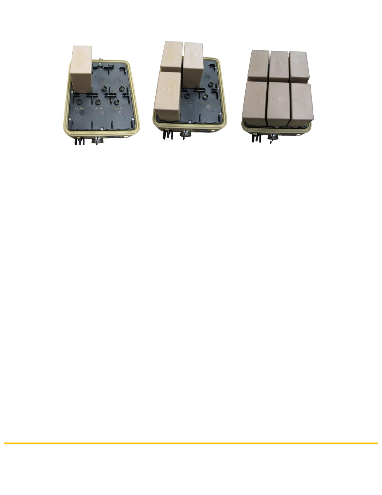
Then, take one BB-2590/U battery,align its connector surface with one of the
(numbered) battery connectors on the 6-PACK, and place the battery on the plastic
interface plate (Figures 1, 2, and 3), making sure the circular and “pogo pin”
connectors are fully engaged. Repeat for the other batteries, until all batteries are
installed. Batteries 1, 2, and 3 are connected in parallel to form one 14.4Vdc battery
bank; batteries 4, 5 and 6 form the second bank.
NOTE:
If fewer than three batteries are installed in a bank, installation of the same number
of batteries in each bank is required if the 6-PACK output is connected in series (for
28.8Vdc output), so that the two banks are maintained at approximately the same
state-of-charge during operation. Such “balanced” loading of the banks is also
recommended in all modes of operation, to minimize charge time. Batteries may be
installed in any bank position when only one or two are being installed in a bank.
BREN-TRONICS, INC
10 Brayton Court
Commack, NY 11725
P: 631-499-5155 | F: 631-499-5504
www.bren-tronics.com
Page 14 of 25
BTE-70791A-T1B / BTE-70791A-T1BR / BTE-70791A-T1BR2
PORTABLE POWER SYSTEM (6-PACK)
OPERATION MANUAL
850069 REV M
Data presented in this document is subject to change without notice.
Model BTE-70791A-T1B is shown
Figure 1 Figure 2 Figure 3
Then, place the lower enclosure over the batteries, aligning it with the upper
enclosure so that the handle and serial-number tag are on the same side. Carefully
move the lower enclosure until it slips down over the batteries, and the gasketed
tongue-and-groove joint between the two enclosures is fully mated. Maintaining
pressure on the lower enclosure as needed, secure the two enclosures together with
the four latches, and turn the assembled 6-PACK upright.
After the battery installation is complete, press and hold the backlight pushbutton (on
the front panel) for at least three seconds to activate the “comm check” feature,
and verify that the LCD display shows a bar for each installed battery, according to
location (Section 7). If a bar is not seen for an installed battery, open the 6-PACK
(the batteries will remain secured in the lower enclosure), check/clean the “button”
contacts of that battery and the 6-PACK pogo pins for that battery location –then
remove the batteries from the lower enclosure and repeat the above installation
process and comm check.
CAUTION:
Keep in mind that the charge voltage of the 6-PACK, in all charging modes, is
16.8Vdc –which is significantly above the normal 16.5Vdc full-charge level
used for the BB-2590/U in its other applications. The BB-2590/U can
safely/reliably/efficiently accept the higher voltage; however, if a battery is
removed from a 6-PACK it should be discharged to 16.5Vdc or less before
being installed in other equipment.

BREN-TRONICS, INC
10 Brayton Court
Commack, NY 11725
P: 631-499-5155 | F: 631-499-5504
www.bren-tronics.com
Page 15 of 25
BTE-70791A-T1B / BTE-70791A-T1BR / BTE-70791A-T1BR2
PORTABLE POWER SYSTEM (6-PACK)
OPERATION MANUAL
850069 REV M
Data presented in this document is subject to change without notice.
6INTERFACE WIRING
6-1 OUTPUT CONNECTOR
6-1-1 BTE-70791A-T1B AND BTE-70791A-T1BR2 (RoHS)
These 6-PACKs utilize a single, bayonet twist-lock connector for the outputs of both
battery banks.
6-1-2 BTE-70791A-T1BR (RoHS)
This 6-PACK utilizes two bayonet twist-lock connector for the outputs of both battery
banks.
Connecting pin A to pin C (via external wiring) and pin B to pin D (via external wiring)
parallels the two banks to produce a single output capable of 60A at 14.4Vdc. Note
that these pin #s for 6-PACK (RoHS) refer to its Power Connector.
Pin:
Size:
Max. current
Function:
A
8
30A
Positive (+) power output, battery bank “1-3”, 14.4Vdc / 30A
B
8
30A
Negative (-) power return, battery bank “1-3”, 14.4Vdc / 30A
C
8
30A
Positive (+) power output, battery bank “4-6”, 14.4Vdc / 30A
D
8
30A
Negative (-) power return, battery bank “4-6”, 14.4Vdc / 30A
1
20
signal-level
RS-485 (+), battery bank “1-3”, referenced to pin B
2
20
signal-level
RS-485 (-), battery bank “1-3”, referenced to pin B
3
20
signal-level
RS-485 (+), battery bank “4-6”, referenced to pin D
4
20
signal-level
RS-485 (-), battery bank “4-6”, referenced to pin D
5
20
signal-level
Reserved for future use.
6
20
signal-level
Reserved for future use.
7
20
signal-level
Reserved for future use.
Pin:
Size:
Max. current
Function:
A
8
30A
Positive (+) power output, battery bank “1-3”, 14.4Vdc / 30A
B
8
30A
Negative (-) power return, battery bank “1-3”, 14.4Vdc / 30A
C
8
30A
Positive (+) power output, battery bank “4-6”, 14.4Vdc / 30A
D
8
30A
Negative (-) power return, battery bank “4-6”, 14.4Vdc / 30A
Pin:
Size:
Max. current
Function:
A
20
signal-level
RS-485 (+), battery bank “1-3”, referenced to Power Connector pin B
B
20
signal-level
RS-485 (-), battery bank “1-3”, referenced to Power Connector pin B
C
20
signal-level
RS-485 (+), battery bank “4-6”, referenced to Power Connector pin D
D
20
signal-level
RS-485 (-), battery bank “4-6”, referenced to Power Connector pin D
E
20
signal-level
Reserved for future use.
F
20
signal-level
Reserved for future use.

BREN-TRONICS, INC
10 Brayton Court
Commack, NY 11725
P: 631-499-5155 | F: 631-499-5504
www.bren-tronics.com
Page 16 of 25
BTE-70791A-T1B / BTE-70791A-T1BR / BTE-70791A-T1BR2
PORTABLE POWER SYSTEM (6-PACK)
OPERATION MANUAL
850069 REV M
Data presented in this document is subject to change without notice.
Connecting pins B and C (via external wiring) places the two banks in series to form
a single output capable of 30A at 28.8Vdc , with pin A being the (+) output and pin D
being the (-) output. Note that these pin #s for 6-PACK (RoHS) refer to the Power
Connector.
The RS-485 connection details are described in the COMMUNICATIONS
INTERFACE section XXX, below. CAUTION:
To avoid inadvertent arcing of the contacts, turn the output switch OFF when
making connections. Such arcing can be generated by inrush currents, or if a
miss-wired/shorted load is accidentally connected to the 6-PACK.
CAUTION:
Note the different ground references for the two RS-485 inputs. To avoid
damage to connected equipment, make sure that the RS-485 input of the
connected equipment is referenced to the same negative power return as the
6-PACK port being connected to it.
CAUTION:
Whenever the outputs of the 6-PACK are connected in series (i.e., by
connecting pins B and C, as described above), make sure that all equipment
connected to the 6-PACK output includes an under voltage lockout function
that interrupts input-current flow whenever the input voltage drops below
20Vdc.
NOTE:
EMC performance is optimized when the output cable also includes an overall braid
(or foil) shield, that is connected (utilizing best practices for EMC compliance) to the
chassis of the 6-PACK via the connector shell, and connected to earth/chassis of the
equipment being powered. This also assures compliance with the requirements of
the EU EMC directive. NOTE:
14.4Vdc is the nominal output voltage of each bank; the output voltage varies with
the state-of-charge of the batteries when operating, from 16.8Vdc (at full charge) to
12Vdc (rated end-of-discharge voltage).
Available output connectors/cables are listed in section 3-2. Bren-Tronics also can
design/manufacture cables to meet user specific requirements.

BREN-TRONICS, INC
10 Brayton Court
Commack, NY 11725
P: 631-499-5155 | F: 631-499-5504
www.bren-tronics.com
Page 17 of 25
BTE-70791A-T1B / BTE-70791A-T1BR / BTE-70791A-T1BR2
PORTABLE POWER SYSTEM (6-PACK)
OPERATION MANUAL
850069 REV M
Data presented in this document is subject to change without notice.
6-2 INPUT CONNECTORS
6-2-1 DC INPUT (ALL 6-PACK VERSIONS)
The 6-PACK utilizes a four-pin connector for 24V NATO, 12V Auto and Solar power
input. Pins A and B are the power-input pins for all modes; pins C and D are
connected to configure the 6-PACK for the input power source being used for
charging, per the table below:
Available DC input connectors/cables are listed in section 4-1. Bren-Tronics also can
design/manufacture cables to meet user specific requirements.
6-2-2 AC INPUT (ALL 6-PACK VERSIONS)
The 6-PACK utilizes a five-pin connector for AC power input. The 6-PACK can
accept 90-264Vac/47-440Hz power, and adjusts its operation automatically to the
applied voltage/frequency –it is compatible with AC utility power mains, worldwide.
WARNING: to prevent electric shock, make sure that pin E of the
AC input is connected to the ground (earth) of the utility power
mains when using AC power!
Available AC input connectors/cables are listed in section 3-1. Bren-Tronics also can
design/manufacture cables to meet user specific requirements.
7CONTROLS
The charger ON/OFF switch is located next to the power-input connectors. One
switch provides ON-OFF control of the charger in all input-power modes.
The output ON/OFF switch is located next to the output connector. This switch is a
circuit breaker that will trip if the connected equipment applies an overload/short-
Pin:
Size:
Max. current
Function:
Connections to source (+) and (-)
24V NATO
12V Auto
Solar
A
12
20A
Positive (-) power input
(+)
(+)
(+)
B
12
20A
Negative (-) power return
(-)
(-)
(-)
C
12
signal-level
Mode select pin
(+) or (-) or NC
(+)
(-) or NC
D
12
signal-level
Mode select pin
(-) or NC
(+)
(+)
MAX. INPUT CURRENT:
15A
20A
20A
INPUT VOLTAGE RANGE:
20-33Vdc
10.5-18Vdc
14-36Vdc
DC input is MIL-STD-1275-compliant
NC = No connection
Pin:
Size:
Max. current
Function:
A
12
2.2A
AC line terminal
B
12
zero
No connection
C
12
2.2A
AC neutral terminal
D
12
zero
No connection
E
12
**Ground **
Chassis ground
MAXIMUM INPUT CURRENT: 2.2A AT 115V –1.1A AT 230V
BREN-TRONICS, INC
10 Brayton Court
Commack, NY 11725
P: 631-499-5155 | F: 631-499-5504
www.bren-tronics.com
Page 18 of 25
BTE-70791A-T1B / BTE-70791A-T1BR / BTE-70791A-T1BR2
PORTABLE POWER SYSTEM (6-PACK)
OPERATION MANUAL
850069 REV M
Data presented in this document is subject to change without notice.
Note: Label shown is for the
BTE-70791A-T1B (other models may vary).
circuit to the output of the 6-PACK. If tripped, it can be reset by manually pushing the
toggle back to the ON position. The output breaker is a “trip-free” type; manually
holding the toggle in the ON position will NOT inhibit tripping. One pole of the
breaker protects each battery bank –if EITHER section experiences an
overload/short-circuit, the breaker interrupts current from BOTH battery banks.
The backlight pushbutton is located on the front panel, between the indicators
(see below). Momentarily pressing this button backlights the LCD displays for
viewing in low-ambient-light conditions. Holding the button down for longer than
three seconds activates the “comm check” feature
described in the next section.
8INDICATORS
8-1 LCD DISPLAYS
There are two five-segment bar-graph-type LCD indicators –
one for each battery bank –located on the front panel. Each
LCD indicates the state-of-charge (SOC) for its associated
bank, as a percentage of the total design capacity of the
6-PACK with all batteries installed in that bank. If only
one or two batteries are installed instead of all three
(or if the older, non-SMBus variant of the BB-2590/U
is being used) the LCD will indicate a lower SOC than that
shown by the individual battery indicator(s),
A backlight is included in each indicator; momentarily
pressing the backlight pushbutton activates the backlights for
five seconds, allowing the user to read the LCDs in low-
ambient-light conditions.
Holding the button down for three seconds activates the “comm check” feature.
The normal, left-justified bar-graph displays are replaced by a set of bars in the
center of each LCD. The presence of a bar indicates that communications is
properly operating to/from BOTH sections of a particular battery in the 6-PACK. The
regular SOC display returns after ten seconds.
If a bar does not appear for an installed battery, open the 6-PACK and check/clean
the “button” contacts on that battery and the 6-PACK pogo pins for that battery
position, then re-install the batteries. If the problem persists, replace the battery.
NOTE:
If a battery bank is discharged, the backlight for that bank’s SOC display may not
operate properly, and/or the comm check display may indicate a problem where
Bars
0
1
2
3
4
5
SOC
0%
1 to 20%
21 to 40%
41 to 60%
61 to 80%
81 to 100%

BREN-TRONICS, INC
10 Brayton Court
Commack, NY 11725
P: 631-499-5155 | F: 631-499-5504
www.bren-tronics.com
Page 19 of 25
BTE-70791A-T1B / BTE-70791A-T1BR / BTE-70791A-T1BR2
PORTABLE POWER SYSTEM (6-PACK)
OPERATION MANUAL
850069 REV M
Data presented in this document is subject to change without notice.
none exists. Check the SOC display; if no bars are present, or only one bar is
present, allow the unit to charge for a few minutes and check the backlight and
comm check function again, before looking for contact/battery problems.
8-2 LED INDICATORS
Two sets of LED indicators –one set for each battery bank –are located below the
LCD displays on the front panel. These indicators illuminate to indicate operational
status, as described in the table below.
CHARGE LED:
Indicates the operational status of the section charger
DARK
Charge power turned off/not applied.
Slow blinking YELLOW
Idle –charger powered, but not presently charging because:
•Power-up or charger reset has just occurred (display will change to
indicate charging, see below)
•Charging was complete, but battery voltage has dropped and the charger
is initiating a recharge (display will change to indicate charging, see
below)
•Charger internal temperature above Temperature-Optimized Charging
operating limit (will automatically restart once temperature falls)
Steady YELLOW
Charging in progress
Steady GREEN
Charging complete
Flashing RED
Battery Fault –charging inhibited because:
•Charger has detected the presence of illegal battery types
•Charger does not detect the presence of any batteries
(If this indication occurs with Bren-Tronics BB-2590/U batteries installed,
checking/cleaning the “pogo pin” contacts of the 6-PACK and/or the “gold button”
contacts of the batteries is recommended)
Steady RED
Charger Fault –charging inhibited because bank overvoltage is detected by
batteries. Resets when voltage drops below overvoltage threshold.
DISCHARGE LED:
Indicates whether the battery is being discharged.
Steady RED
Battery is being discharged - continued operation with this indicator illuminated
will eventually discharge the battery. This can occur even when the charger is
operating, if the load current is higher than the charge current.
Flashing RED
Power-up LED check –occurs when charger is mated to batteries
9POWER INPUT PRIORITY
When multiple power sources are connected to the 6-PACK inputs, the priority of
use is shown in the table below. Primary power is used as long as it is available; if it
is interrupted, the unit automatically switches to operation from secondary power.
Combination
Primary
Secondary
AC and 24V
24V
AC
AC and Solar
SOLAR
AC
AC and 12V
AC
12V

BREN-TRONICS, INC
10 Brayton Court
Commack, NY 11725
P: 631-499-5155 | F: 631-499-5504
www.bren-tronics.com
Page 20 of 25
BTE-70791A-T1B / BTE-70791A-T1BR / BTE-70791A-T1BR2
PORTABLE POWER SYSTEM (6-PACK)
OPERATION MANUAL
850069 REV M
Data presented in this document is subject to change without notice.
10 PROTECTIVE DEVICES
In addition to the output breaker described above, the 6-PACK utilizes electronic
protection to prevent unsafe/damaging conditions from occurring:
•The internal protection circuit in each BB-2590/U battery is always active,
protecting the battery from unsafe/damaging conditions such as overvoltage,
under voltage, over current, and over temperature.
•The operating temperature of each charger is monitored. Charging is paused
if the temperature starts to exceed the safe limit, and automatically restarts
once temperature drops back below that limit.
•Each charger microcontroller includes redundant firmware and hardware
overvoltage protection, which inhibits charging if a bank-overvoltage condition
is detected.
•The voltage of each bank is also monitored via the SMBus interface to the
batteries; charging is interrupted if bank voltage exceeds its safe limit.
•The chargers and power converters (for 12V and AC operation) are protected
from transient over voltages in accordance with the requirements of
EN61000-6-2 and MIL-STD-1275 by passive and active electronic protection.
•Each power converter includes an integral output current limit.
•DC input current is monitored; charging operation is interrupted when
excessive input current is detected.
As backup, the DC power source feeding the 6-PACK is protected by a 30A
automotive-type time-delay fuse, located adjacent to the battery contacts/pogo pins.
A spare 30A fuse is also provided. The AC input is internally fused. If the DC fuse
blows, and the spare blows when installed in its place –or if the 6-PACK will not
power up on AC with a known-good power cord -- the 6-PACK is permanently
inoperative and in need of repair.
11 OPERATOR MAINTENANCE INSTRUCTIONS
Periodic maintenance, inspection and cleaning will help insure the 6-PACK is kept at
full readiness.
11-1 CLEANING
1. Brush loose dirt and dust from the charger. Low-pressure air may be used to
remove heavy dust from the case, connectors and power switches. Avoid
blowing dust into the unit. Low-pressure air may be blown into the left and
right air vents at the edge of the control panel to help remove internal dust.
2. Wipe surfaces with a damp (not wet) rag. Non-solvent cleaners maybe used
(Windex™, Fantastik™, Formula 409™). Do not spray or drip water or
cleaners onto the panel or into the connectors.
This manual suits for next models
5
Table of contents
Popular Power Supply manuals by other brands


Monacor
Monacor PSS-600E quick start guide

BIO RAD
BIO RAD PowerPac 200 instruction manual

Elektro-Automatik
Elektro-Automatik PSI 9000 DT Series operating manual

Whelen Engineering Company
Whelen Engineering Company UPS148C installation guide

hager
hager Essensya WE111 Series quick start guide

Stanley
Stanley GT13 Safety, operation and maintenance user's manual