Sargent EC325 User manual

EC325PowerControlSystem
Issue 02 Page 1 of16 12 December2008
1 Template
Instructions
<<Deletebefore
use>>
1KeyFeatures
· 325W(~25A)PowerConverter-Convertsthe 230Vmainssupplyinto12vDC powerto run
the leisure equipment and supplythe batterycharger.
· Intelligent ‘offline’BatteryCharger-Usesa process ofdisconnecting the leisurebatteryfrom
the leisure equipment during thecharging process,which allowsthe batterychargerto
charge batteriesquicker, recoverheavilydischarged batteriesandachieve ahigherfinal
charge levelthan traditionalbatterychargers.
· Built-in dualSolarRegulator-Allowsthe direct connectionofa 20to 100Wsolarpanel
without the need foradditionalcomponents. The dualregulatorchargesboth the vehicleand
leisure batteriessimultaneously.
· SystemMonitorCircuit -Monitors keycomponentswithinthe powersupplyto ensure
optimumoperation.Asimple‘trafficlight’indicatorshowsthe powersupplystatus.
· EnhancedDigitalControlPanel-With scrolling menu system, batterycondition (voltage and
current),watertanklevels,tankand batterylevelwarningswith batteryprotect circuit, alarm
clockand programmable event timer.
2System Overview
The following diagramshowsthe typicalconfiguration ofthe EC325 system. The keycomponent is
the EC325 powersupplyunit (PSU),whichisthe hub ofthe systemand providesconnectivityto the
ancillarycomponentsand the EC325 digitalcontrolpanel.
12v LEISURE
BATTERY
12v LEISURE
BATTERY
12v VEHICLE
BATTERY
12v VEHICLE
BATTERY
REMOTEREMOTE
12v
EQUIPMENT
240v
EQUIPMENT
240v
IN
240v
IN
SENSOR
INPUTS
CONTROLPANEL
EC325
CONTROLPANEL
EC325 EXTTEMPEXTTEMP UPTO 100W
SOLAR
PANEL
MainsControl
Equipment
EC325PowerSupplyUnit
BAT TEMPBAT TEMP
FRESH
WATERTANK
WASTE
WATERTANK
EC200
Offline
Intelligent
Charger
100WSolar
Regulator
325W
230v - 12v
Converter
Relays
EC200
Offline
Intelligent
Charger
100WSolar
Regulator
325W
230v - 12v
Converter
Relays
12v LEISURE
BATTERY
12v LEISURE
BATTERY

EC325PowerControlSystem
Issue 02 Page 2 of16 12 December2008
1 Template
Instructions
<<Deletebefore
use>>
3PowerSupplyDetails
Forthe safe operationofall electricalequipment within yourLeisureVehicleitisimportant that you
read and fullyunderstand these instructions. If you are unsureofanypointplease contactyourdealer
/ distributorforadvice before use.
The following diagramshowsthe EC325PSUlayout.
WARNING
Underheavyloadsthe EC325PSU case maybecome hot. ALWAYSensure the ventilation slotsand
the cooling fan have aclearflow ofair. Do not place combustible materialsagainst / adjacentto the
EC325PSU. The PSUwillshutdown ifoverheated andwill restart automaticallywhen cool.
3.1BatteryCharger
The EC325PSUincorporatesan intelligent ‘offline’batterychargerthat disconnectsthe leisure
equipment fromthe batterywhileit isbeing charged. Thisprocess allowsthe chargerto use higher
chargingvoltagesandto accuratelycontrolthe charging current. No otherequipment maybe
connected directlytothebatterywhile charging istaking place. Thisintelligent batterychargerdraws
powerfromthe powerconverter(see 3.4)when the mains230vsupplyisturnedon and fromthe
vehiclealternatorwhen the engine isrunning, thereforethe leisure batteryisalwayscharged via the
intelligent batterycharger.
WARNING
Highervoltagesmaybe present at the battery(<=18v).Do not connectANYequipment to the battery
while the chargerisoperating. Failure to complywith thiswarning maylead to equipment damage and
willaffect the batterychargerperformance.
The EC325 systemalso incorporatesa batterycompartment
temperature sensor(see photograph),whichmonitors the battery
ambient temperature to allowthe chargerto adjust the charging
current ifthe batteryisverycoldorhot.
Power
Switch
Polarity
Indicator
RCD &
3 MCB’s
DC
Fuses
System
Monitor

EC325PowerControlSystem
Issue 02 Page 3 of16 12 December2008
1 Template
Instructions
<<Deletebefore
use>>
3.2Residual CurrentDevice &MiniatureCircuitBreakers
The Residual Current Device(RCD) is basicallyprovided
toprotectthe userfromlethalelectricshock. The RCD will
turnoff (trip) ifthe current flowing inthe liveconductor
doesnotfullyreturndownthe neutralconductor, i.e. some
current ispassing through apersondowntoearthor
throughafaultyappliance.
Toensurethe RCD isworkingcorrectly, thetest button
should beoperatedeachtimethe vehicleisconnectedto
the mainssupply(seesection 5.1)
The MiniatureCircuit Breakers(MCB’s) operatein asimilar
waytotraditional fusesand areprovidedtoprotectthe
wiring installation fromoverloador short circuit. If an
overload occurstheMCB will switchoffthe supply. Ifthis
occursyou shouldinvestigatethe causeofthe fault before
switchingtheMCB back on.
The following table showsthe rating and circuitallocation forthe three MCB’s
MCB Rating Wire Colour Description
1 10 Amps White 230vSockets
2 10 Amps White (Yellow forheater) Extra 230vSockets/ Heater
3 6 Amps Black(Blue forwaterheater) Fridge /WaterHeater/ 12vCharger
(internallyconnected)
3.3SystemMonitor
The systemmonitorcircuitchecks the powersupplykeycomponentsto ensure
optimumoperation.The current statusisdisplayedon the front ofthePSU by
the meansofa clearindication thatilluminatesindifferent colours depending
on the PSU status.
Left
Centre
Right
Status Indication description
- - G Good Mainssupplyon,PSU statusgood.
- - - Good Mainssupplyoff, PSU statusgood.
- O G Warning
Mainssupplyon,PSUinwarning mode. In thismode the PSU will
limit the output current to protect the unit fromdamage.It isstillsafe
to use the unit but the faultshould beinvestigated. Typicalcausesare
batterytemperature sensorunplugged, cooling fan notworking,
internalsensors disconnected orfailed.
- O - Warning Mainssupplyoff, PSUinwarning mode.
R O G Failure
Mainssupplyon,PSUin overheat failuremode. In thismode the PSU
willshutdown and allequipment will be switchedoff. The cooling fan
willcontinue to run until theunit coolsdown. Typicalcausesare short-
circuited DC output, batteryconnected in reverse, cooling fan failed,
cooling ventsblocked / covered, problemcaused byprolonged usein
warning mode.
R - G Failure Mainssupplyon,PSUin overheat failuremode.
R O - Failure Mainssupplyoff, PSUin overheat failuremode.
Test
Button
RCD
MCB’s

EC325PowerControlSystem
Issue 02 Page 4 of16 12 December2008
1 Template
Instructions
<<Deletebefore
use>>
3.4PowerConverter
The EC325PSU containsa powerconverterthat powersthe leisureequipment when the mainssupply
isconnected. Thismodulesupplies13.5vDC to the leisure equipment up to amaximumof25 Amps
(325 Watts).
The powerconverteralso suppliespowerto the intelligent batterycharger, therefore the available
powerisdistributed between theleisureload and the charger,withtheleisureload taking priorityas
perthefollowing example:
Leisureload Availablepowerforthe batterycharger
10A 15A
15A 10A
20A 5A
25A 0A
3.5SolarPanel Converter
The EC325PSUincorporatesa built-indualchannelSolarRegulatorthat allowsthe direct connection
ofa 20 to 100Wsolarpanelwithout the need foradditionalcomponents. The dualregulatorcharges
both the vehicle and leisurebatteriessimultaneouslyand connectsto the PSU viaa dedicated
connectoron the base ofthe unit (see section6.5forconnectordetails).
Aconnection harness isavailable fromyourdealer, the partnumberis59065-07.
3.6Fuses
WARNING
When replacing fusesalwaysreplace a fusewiththecorrect value. NEVER replace witha highervalue /
ratingasthiscould damage the wiring harness. Ifa replacement fuse ‘blows’ do not keep replacing the
fuse asyou could damage the wiring harness. Pleaseinvestigate the fault and contactyourdealer.
The following table showsthe fuse allocation forthe 12 fusesfitted to the EC325PSU.
Fuse Rating Fuse Colour Wire Colour Description
1 20 Amps Yellow Brown/ Blue LeisureBattery
2 20 Amps Yellow Brown/ Green VehicleBattery
3 5 Amps Tan Brown/Yellow Permanent Supply(Radio/ Fridge)
4 10 Amps Red Green / Blue WaterPump 1
5 10 Amps Red Green / White WaterPump 2
6 10 Amps Red Grey/ Red AuxiliarySupply(Awning / EntryLight)
7 15 Amps Blue Grey Front Lights
8 15 Amps Blue Pink RearLights
9 10 Amps Red Yellow / White 12vSockets/ TVAmplifier/ Entertainment
10 10 Amps Red Black/ tracer Fans/ HeaterFans
11 5 Amps Tan Yellow / Green IgnitionsSupply(Heaters / Cooker)
12 10 Amps Red Purple Toilet Pump
The following table showsdetailsofthe fuse(s) located at the Leisure battery.
Battery1 20 Amps Yellow Brown/ Blue Fuse remotelylocated nearbattery
Battery2 20 Amps Yellow Brown/ Blue Fuse remotelylocated nearbattery2
(where fitted)

EC325PowerControlSystem
Issue 02 Page 5 of16 12 December2008
1 Template
Instructions
<<Deletebefore
use>>
3.7Battery
A)Type / Selection
Foroptimumperformance and safetyitisessentialthat onlya proprietarybrand LEISUREbatteryis
used with a typicalcapacityof75 to 120Ah(Ampere / hours). AnormalcarbatteryisNOTsuitable.
Thisbatteryshouldalwaysbe connected when the systemisin use.
The EC325PSUisconfigured atthefactoryforstandard lead acidleisure batteries, howeveryour
dealercan reconfigurethe unitto workwithGelbatteriesifrequired. The dealermaymake a small
charge forundertaking thiswork.
Some vehicleinstallationscan caterfortwoleisure batteriesconnected in parallel. In these casesit is
recommended that two identicalbatteriesare used.
The batteryfeed isfitted with an inline fuse between the batteryandtheelectricalharness, andis
usuallylocated immediatelyoutside the batterycompartment orwithin 500mmofthe battery. The
maximumrating ofthisfuse is20Aperbattery.Iftwo ormore batteriesare fitted the maximumtotal
fusing value must not exceed 40A.
B)Installation & Removal
Alwaysdisconnect the 230vmainssupplyandturn theEC325PSU chargerswitchto the OFF (0)
position before removing orinstallingthebattery.
When connecting the battery,ensure that the correct polarityisobserved (blackis negative[-] and red
ispositive [+])and that the terminalsare securelyfastened. Crocodile clipsmustnot be used.
WARNING
Explosive gasesmaybe present at the battery.Takecare to prevent flamesand sparks in thevicinity
ofthe batteryand do not smoke.
C)Operation / Servicing
Undernormalcircumstancesit shouldnot be necessaryto remove thebatteryotherthanforroutine
inspection ofthe terminalsand “toppingup”ofthe batteryfluidwhere applicable. Please see
instructionssupplied withthe battery.
Note: Do not overdischarge thebattery.One ofthe most common causesofbatteryfailureiswhen
the batteryisdischarged below therecommended levelofapproximately10v. Discharginga battery
belowthisfigure can causepermanent damage to one ormore ofthe cellswithin the battery.
To preventoverdischarge, the EC325 systemincorporatesa batteryprotect circuit that warnsand
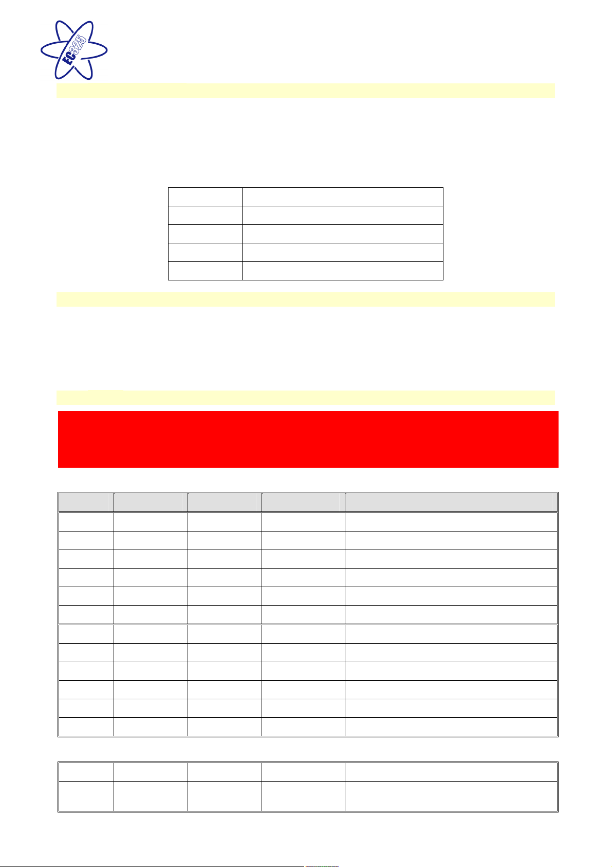
then disconnectsthebatterieswhentheyfallbelow the followingconditions:
Battery
Voltage
cut off Action aftercut off Notes
Vehicle 10.9v
Batteryselection is
changed fromVehicle
batterytoLeisure
battery. Ifthe leisure
batteryisbelow6v
then a furtherwarning
willoccur(see below).
Thiscut off levelisdesigned to protect the vehicle
batteryfromoverdischarge. The 10.9vlevel
ensuresthere issufficient powerin the batteryto
run thevehicleelectronics and startthe vehicle.
Thiscut off onlyappliestopowerdrawn fromthe
batterybythe leisure equipment; itwill not protect
the batteryif youleave thevehiclelightson.
Leisure 9v Poweristurned off
Thisisan emergencycutoff leveltoprotectthe
batteryfromsevere damage. You should not rely
on thiscut off levelduring normaloperation, but
manage yourpowerconsumption to a discharge
levelof10v.
Thiscut off onlyappliestopowerdrawn fromthe
batterybythe leisure equipment that iscontrolled
bythe controlpanelpowerswitch; itwillnotprotect
the batteryfromdischarge bythe radioorother
permanentlyconnectedequipment.

EC325PowerControlSystem
Issue 02 Page 6 of16 12 December2008
1 Template
Instructions
<<Deletebefore
use>>
4Control Panel Details
4.1Layoutand Buttons
The following diagramshowsthe controlpanellayout and button functions.
Note: to remove the decorative bezel, pull down and lift forward asindicated bythe blue arrows.
Item Function Options/ Notes
PowerON/ OFF Use to turn the main leisurepoweron and
off.
The adjacent LEDisilluminated when
the powerisON.
BatterySELECT
Use to select the LeisureorVehiclebattery.
Press the button to toggle between the
leisure andvehiclebatteries. When a
batteryisselected thisbatterywillbe used
asthe powersource andwill alsobe
charged bythecharger.
The adjacent LEDisilluminated when
the VEHICLEbatteryisselected; by
defaultwhen the powerisinitiallyturned
on the Leisurebatteryisselected and is
indicated bythe batteryselect LEDoff.
Pump ON/ OFF Use to turn thewaterpump(s) poweron and
off (see section 4.3)
The adjacent LEDisilluminated when
the pump powerisON.
AuxON / OFF
Use to turn the Auxiliarypoweron and off
(see manufacturers handbookfordetailof
what itemsare operated bythe auxiliary
function).
The adjacent LEDisilluminated when
the auxiliarypowerisON.
ScrollUP
Use to scrollthedisplayup (settingssection
ofthe menu)oradjust the selected setting
(see section 4.3)
ScrollDOWN ▼
Use to scrollthedisplaydown (readings
section ofthe menu)oradjust the selected
setting (see section 4.2)
Note: the menu screensoperate in a
continuousloop, thereforeyou can use
eithertheUPorDOWN buttonsto
move to anyscreen
Select ◄Use to select a menu itemwithin the
settingssection(see section 4.2&4.3)
Use to move tothenext setting,when
entering alarm/ event times
Note: the displaybacklight operated forapproximately6 secondsafteranykeypress.
Power
ON / OFF
Pump(s)
ON / OFF
Auxiliary
ON / OFF
Battery
Select
Indicator
Lamps x4
Scroll
Up/
Adjust
Scroll
Down/
Adjust
Select
LCD
Display

EC325PowerControlSystem
Issue 02 Page 7 of16 12 December2008
1 Template
Instructions
<<Deletebefore
use>>
4.2Menu Functions-Readingssection
Display Description Options/ Notes
EC325 v1.3H
12:00 23.9°C
Main ControlPaneldisplayshowing
modelnumber(EC325),software
version number(v1.3), specification
(H), current time (12:00)and
Internaltemperature (23.9°C)in
centigrade
The addition ofa asterisk(*)
in the top left ofthe display
indicatesthat the alarmisset
The addition ofa hash (#)in
the top right ofthe display
indicatesthat the event timer
isset
The addition oftheletters ‘AC’
in the centre ofthe display
indicatesthat the ACMains
supplyisswitched on
Leisure Battery
12.5v (Good)
▼
Voltage reading and battery
condition description fortheon-
boardleisure battery
See also3.7C
Less than10.9=(Poor)
10.9 to 11.8 =(Fair)
11.9 to 14.4 =(Good)
Vehicle Battery
13.3v (Good)
▼
Voltage reading and battery
condition description forthevehicle
battery
See also3.7C
Less than10.9=(Poor)
10.9 to 11.8 =(Fair)
11.9 to 14.4 =(Good)
Mains Supply
ON
▼
Indication ofthe230vmainssupply. ON =mainssupplyon
OFF =mainssupplyoff
Leisure Battery
=Lead Acid
▼
Showsthe type ofbattery
configured withintheEC325PSU.
The leisurebatterytype can
be changedwithin the
EC325PSU to accommodate
Gelbatteriesifrequired (see
section 3.7Afordetails)
Fresh Water
25% Full
▼
Waterlevelin the freshwatertank
(5 measurement levels)
Ifthe waterpump powerswitch is
turned ONand thewaterlevel
dropsbelow 25%awarning beep
willbe heard and the LCD display
willflash. To cancelthewarning,
press the select (◄) button. The
warning willnot be repeated unless
the waterpump powerswitch is
turned off and on again.Thisisto
ensure thewarning doesnot
become a nuisance.
0%<¼Full(Nearlyempty)
25%>= ¼Full
50%>= ½Full
75%>= ¾Full
100%=Full

EC325PowerControlSystem
Issue 02 Page 8 of16 12 December2008
1 Template
Instructions
<<Deletebefore
use>>
Display Description Options/ Notes
Waste Water
0% Full
▼
Waterlevelin thewaste watertank
(2 measurement levels)
Ifthe waterpump powerswitch is
turned ONand thewastewater
levelrisesto 100%a warning beep
willbe heard and the LCD display
willflash. To cancelthewarning,
press the select (◄) button. The
warning willnot be repeated unless
the waterpump powerswitch is
turned off and on again.Thisisto
ensure thewarning doesnot
become a nuisance.
0%<½Full
50%>= ½Full(optionallevel
that isnotnormallyfitted by
mostmanufacturers)
100%=Full
External Temp
26.5°C
▼
Externaltemperature (in degrees
centigrade)asmeasured bythe
externaltemperature probe
[Onlyavailable in H specification
systems-see start of section 4.2]
Battery Current
5.4 Amps
▼
Current (in Amps) being drawn from
orchargedinto the selected battery
Ifa solarpanelisfitted thisdisplay
willinclude the current being
provided bythe solarpanel.
[Onlyavailable in H specification
systems-see start of section 4.2]
Negative figure (-) =current
being drawn fromthe selected
battery
Positive figure=current being
used tochargetheselected
battery

EC325PowerControlSystem
Issue 02 Page 9 of16 12 December2008
1 Template
Instructions
<<Deletebefore
use>>
4.3Menu Functions-Settingssection
Display Description Options/ Notes
Pump Select?
<Internal>
▼
Showsthe currentlyselected pump
that willbe operated bypressing the
pump on / off switch (TAP symbol)
Use the selectbutton (◄)to change
Note: if yourwaterpump stops
working, thissetting mayhavebeen
inadvertentlychanged.
<INTERNAL>=The internal
pump willbe operatedbythe
pump switch
<EXTERNAL>=The External
pump willbe operatedbythe
pump switch
<BOTH>=Both the Internal
and Externalpumpswill be
operated simultaneouslyby
the pump switch
Water Tank Fill?
<Start 1 Min>
▼
Allowsoperationofthe External
pump fora period ofone minute
(forfilling the internaltankfromthe
externaltank)
Use the selectbutton (◄)to START
(orSTOP)
Will haveno effect ifthe
Externalpump isalready
switched on (seeabove)
Will not operate ifthe Internal
(Fresh)watertankisshowing
100%Full
Clock Set?
12:00
▼
Access to set the internalclock
Press the select button (◄)to
select HOUR
Use the up /down ( ▼)buttonsto
change
Press the select button (◄)to
select MINUTE
Use the up /down ( ▼)buttonsto
change
Press the select button (◄)to exit
Please note the clockusesa
24 hourcycle
Alarm Set?
12:00
▼
Access to set the alarmclock
Press the select button (◄)to
select HOUR
Use the up /down ( ▼)buttonsto
change
Press the select button (◄)to
select MINUTE
Use the up /down ( ▼)buttonsto
change
Press the select button (◄)to exit
Please note the alarmusesa
24 hourcycle
Alarm = Off
▼
Showsthe alarmclockstatus(on /
off)
Press the select button (◄)to
switch between OFF orON
The addition ofa asterisk(*)
in the top left ofthe main
EC325 displayindicatesthat
the alarmisset

EC325PowerControlSystem
Issue 02 Page 10of16 12 December2008
1 Template
Instructions
<<Deletebefore
use>>
Display Description Options/ Notes
Set Event Timer?
▼
Access to set the event timer
Press the select button (◄)to
select HOUR ON
Use the up /down ( ▼)buttonsto
change
Press the select button (◄)to
select MINUTEON
Use the up /down ( ▼)buttonsto
change
Press the select button (◄)to
select HOUR OFF
Use the up /down ( ▼)buttonsto
change
Press the select button (◄)to
select MINUTEOFF
Use the up /down ( ▼)buttonsto
change
Press the select button (◄)to exit
Please note the event timer
usesa 24hourcycle
The event timerisused to
switch the controlpanel
poweron and off in the
absenceofthe user/
occupier.
See section4.4 forfurther
details.
[Onlyavailable in H and M
specification systems]
Event Timer =Off
12:00 till 12:00
▼
Showsthe event timerstatus(OFF /
ON)and the current On and Off
times
Press the select button (◄)to
switch between OFF orON
[Onlyavailable in H and M
specification systems]
The addition ofa hash (#)in
the top right ofthe main
EC325 displayindicatesthat
the event timerisset
4.4EventTimerexample
The event timerisdesigned to allowthe leisurevehicle userto turn the 12vpoweron oroff (in thesame way
asusingthecontrolpanelpowerbutton)withoutbeing in thevehicle. Thisallowslightsorotherequipment
to beturned on oroff at a predetermined time.
Example -to turnon one interiorlight at11.00pm for1 hour
Ensure the clockisset to the correct time
Scrollto the ‘Set Event Timer?’screen
Following the instruction insection 4.3, set the ON time to 23:00 and the OFF time to 24:00
Scrollto the ‘Event Timer=’ screen and select ON
Scrollto the main controlpaneldisplayand ensurea hash (#)isdisplayedin the right ofthe display
Turn all lightsand 12vequipment offin thevehicleexcept the light that youwant the event timerto
automaticallyswitchon
Turn the 12vpoweroff on the controlpanel
Exit the vehicle
At 11:00pm(23:00)thecontrolpanelwillswitchthe12vpoweron and therefore anyequipment thatwasleft
switched on willbe turned on. The 12vpowerwill be switched off at Midnight (24:00).

EC325PowerControlSystem
Issue 02 Page 11of16 12 December2008
1 Template
Instructions
<<Deletebefore
use>>
4.5Warning Messages
Vehicle
Battery
Dangerously
Low
ThisWARNINGdisplayindicatesthatthe
Vehiclebatteryvoltage islow(10.9 voltsor
less). The panelwillbeep forone minute and
then switch overto the Leisure batteryto
prevent draining the Vehicle battery.
You can switch overtothe
Leisurebatteryimmediately
(and cancelthe beep)byusing
the batteryselectorswitch
Leisure
Battery
Dangerously
Low
ThisWARNINGdisplayindicatesthatthe
Leisurebatteryvoltage islow(6voltsorless).
The panelwillbeep forone minute andthen
switch the poweroff to prevent damage to the
leisure battery.
See section3.7 forfurther
details
PSU Over Temp
Cooling Down
ThisWARNINGindicatesthat the EC325PSU
hasoverheated and iscooling down. The
chargerand powerconverterwillshutdown to
allowthe cooling fan to reduce theheat ofthe
PSU.
Thiswarningisunlikelyto
occurundernormaloperation.
If yourPSUdoesoverheat
please checkthe ventilation
slotsforblockagesetc.
System
disabled
Engine
started
ThisWARNINGdisplayindicatesthatthe
systemhasbeen disabledbecause the vehicle
engine isrunning
EMC (Electro Magnetic
Compatibility)directive
89/336/EECrequiresthat
electricalaccessorieswithin the
vehiclearedisconnected while
the vehicleisin motion
5Operational &SafetyInformation
5.1Connecting totheMainssupply-Safetychecks
Foryoursafetyit is IMPORTANT that you followtheseconnectionsinstructionseach timeyourLeisure
Vehicleisconnectedto a mainssupply.
A)Ensure suitabilityof theMains Supply.YourLeisure Vehicle shouldonlybe connected to an
approved supplythat meetsthe requirementsofBS7671. In most casesthe site warden will hold
information regarding suitabilityofsupply.Ifusing a generatoryou also need to complywith the
requirements/ instructionssupplied with the generator. Pleasenote that some electronic
generators maynot be compatiblewith yourleisure system.
B)Switchthe EC325PSU internal PowerConverterOFF. Locate the green ‘Charger’powerswitch
on the EC325PSUand ensure theswitchisin the OFF (0)positionbefore connection to the mains
supply.
C)Connectthe Hook-up Lead. Firstlyconnect the supplied hook-up lead (orange cablewith blue
connectors) to the LeisureVehicleand then connect to themainssupply.
D)Check Residual Current Device operation. Locate the RCDwithin theEC325PSUand ensure
the RCD isswitched on (leverin up position). Press the ‘TEST’button and confirmthat the RCD
turnsoff (leverin downposition).Switch the RCD back to the on position (leverin up position). If
the test button failed to operate the RCD see section 5.2.
E)Check correctPolarity. Locate the ‘ReversePolarity’indicatoron the EC325PSU andensure
that the indicatorisNOTilluminated. Ifthe indicatorisilluminated see section 5.2.

EC325PowerControlSystem
Issue 02 Page 12of16 12 December2008
1 Template
Instructions
<<Deletebefore
use>>
F) Check Miniature CircuitBreakers. Locate the MCB’s within the EC325PSU (adjacent to the
RCD)and ensuretheyareallintheON (up)position.IfanyMCB’sfail to latchinthe on position
see section 5.2.
G) Turnthe EC325PSU ON. Locate the green powerswitch on the EC325PSUandturn to the ON(I)
position.The switchwillilluminate when turned on.
H)Check operation of equipment. It isnowsafe to checkthe operation ofthe 12vand 230v
equipment.
5.2Common FaultTable
Fault Possible Cause ProposedFix
Connectinglead between
the siteand Leisure
Vehicle notconnected
Checkandconnect lead asper 5.1C
Checkalsoinputconnectoratthe baseof theEC325PSU
RCD switched off Reset RCD asper5.1D
RCD not operating
correctly
Checksupplypolarity; if the RCD continuestofailcontact your
Dealer, asthereisprobablyan equipment orwiring fault.
MCB switched off
Reset MCB byswitching OFF (downposition)thenback ON(up
position), ifthe MCB continuestofail contact yourDealer, asthereis
probablyan equipment orwiring fault.
Noor deficientsupply
fromsite Contact siteWardenforassistance
No230 volt
outputfromPSU
Other fault Contact your Dealer
MainsSupplyreversed?
The reversepolaritylight isdesigned toilluminatewhen theLiveand
Neutral supplyhasbeen reversed /crossed over. If thelight
illuminatesthereisaproblemwiththe sitesupplyor thecable
connecting the supplytoyourvehicle. The lightis designed towork
on UK electricalsupplies(wherethe neutral conductor isconnected
toearthatthe substation). If you areusing yourvehicle outside the
UK thislight mayilluminatewhen no fault exists.Inthesecases
consultthe sitewarden foradvise.
ReversePolarity
lightis
illuminatedon
PSU
Generatorbeing used
The ReversePolaritywarning lightis on when usingmyGenerator.
Thisis anormalside effect when usingsometypesof generator.
Instead of connecting the neutral conductortoearth,somegenerators
centretapthe earthconnectionmakingbothneutralandlive
conductors110vaboveearth.This110vdifferencecausestheneon
polarityindicator toilluminate.Inmostcasesitis still safetousethe
generator, but pleaseconsult the generator handbookfor further
information.
Control Panelhasno
display
Checkbatteries, turnEC325PSU charger switchon,and ensure
mainssupplyis connected.
Checkcontrolpanel connectingleadat EC325PSU and behind
Control Panel
Contact your Dealer
12vPower turnsoff
Batterysavefeaturehasoperated toprotecttheVehiclebatteryand
or the Leisurebattery. See 3.7C
Enginehasbeen started, all equipmenthasbeen disconnected to
meet EMC requirements.See4.4
Control Panel
Problems
Control Paneldisplay
corrupt / erraticfunction
Observecontrolpanel handlinginstructions
Control panel softwaremayhavecrashed.Reboot controlpanel by
turningoffthe EC325PSU charger switchandremoving fuses1& 2
at the EC325PSU (2x20A fusesforleisureandvehicle batteries).
Wait 30secondsthenreplacethe fusesandturnthechargerswitch
on.
(Alternatively, removethebezel atthe control panelbypullingdown
in thecentreat thebottom, unplug the control panelmulti-way
connector, wait 30 seconds,then plug backinandreassemble.

EC325PowerControlSystem
Issue 02 Page 13of16 12 December2008
1 Template
Instructions
<<Deletebefore
use>>
Fault Possible Cause ProposedFix
Control Panelcontrast
poor
Observecontrolpanel handlinginstructions
Removecontrolpanelasabovebutdo not unplug. Carefullyadjust
contrastpreset (small adjuster) on backofcontrol panelusing
jewellersscrewdriver
Control Panelcurrent
readingincorrect
Re-calibratethecurrentsensor asfollows:
Withthe charger switchturnedoff, and the power turned off at the
control panel(no LED’son)
Scrolldown ▼the displayuntilbatterycurrent isshown
Hold downtheselect button ◄(left arrow) until 'calibrating….'
appears;keepthebutton pressed untilthebatterycurrent readingre-
appears. Releasethe button.
Nowrepeat the processtostorethe newsetting.
Hold downtheselect button ◄(left arrow) until 'calibrating….'
appears;keepthebutton pressed untilthebatterycurrent readingre-
appears.
The currentreadingshouldnowbe correct
No230vsupply Checkallabove
Charger notswitched on Switchchargerswitchon(I) position,switchwill illuminate
Batterynotconnected and
/ or charged Install charged batteryasper3.7
Power switchon control
panelnotswitchedtoON Turnpower on atcontrol panel
Batteryflat/ Batteryfuse
blown
Rechargebattery, check fuses, checkcharging voltage is presentat
battery
Fuseblown Checkallfusesareintact and the correct valuefuseisinstalled as
per fusetable
Equipmentswitchedoff /
unplugged Checkequipmentis switchedon andconnectedtothe 12vsupply
PSU overheated/ auto
shutdownoperated
Reduceload onsystem.AllowPSU tocool down. PSU will
automaticallyrestart when cool. See3.2
No12 voltoutput
fromPSU
Other fault Contact your Dealer
Fuseblown Replacefuse
Pumpturnedoff Turnpumpon bypressingthepumpbutton at theEC325 control
panel(tapsymbol)
Pumpnot
working
Settingincorrect
Boththeinternalandexternal pumpfeedsarecontrolledfromthe
EC325 controlpanel.Toalterthe settingofthe pumpswitch(tap
button)seesection 4.3
Ensurethe settingmatchesyour desiredrequirement.

EC325PowerControlSystem
Issue 02 Page 14of16 12 December2008
1 Template
Instructions
<<Deletebefore
use>>
6Technical Data& Approvals
6.1OutlineSpecification
INPUT230v 230 Volts/ 0to16Amps +/ - 10%
OUTPUT230v RCD protected,3xMCB outputsof 10,10 and 6A via 2x
9wayconnectors
INPUT12v 2x20A batteryinputsvia asingle 6wayconnector
SOLAR INPUT 1xDedicatedsolar panelinput (20 to100Wpanel)via a4
wayconnector
OUTPUT12v 25A total output via 4x16A switched channelsprotected
by12 fused outputsviaa15wayconnector
Integrated CHARGER
Input220-240 VoltsAC +/- 10%, Frequency50 Hz+/- 6%,
Current 3Amax.
DC Output 13.5Voltsnominal,Current25 Ampsmax(325
Watts).
SignalINPUT 4xFreshwater level,2xWastewater level,1xEngine
running, 2xbatterytempsensor via a10wayconnector
Freshwater negativesensed
Wastewater negativesensed
DataIN / OUT Datacommunication and power toControl Panelvia 20
wayIDC header connector
IP rating IP31
Operating
temperature
Ambient 0to35° Centigrade
PSU casetemperaturewithfullload65°C Max
Automaticshutdownandrestart
if overheated / overloaded
6.2Dimensions
Overall size(HxWxD) 240 x370 x110mm Fixing centres210 x360mm
EC325PSU
Clearances75mmabove,20mmbelow, 50mmleft & right Weight 3.8Kg
Overall size(HxWxD) 80 x193 x40mm Fixing centres175mm
EC325 CONTROL
PANEL Cut-outsize(HxW) 60 x165mm Weight 170g
6.3Approvals
System: BSEN 1648-1, BSEN1648-2compliant, BS7671:2001 compliant
Residual Current Device: RCD40A 30mA trip toBS EN 61008
MiniatureCircuit Breakers: MCB’s (10& 6A) typeC 6000A breaking capacitytoBSEN 60898
ElectroMagneticCompatibility(EMC) directive89/336/EEC
Integrated Charger: BS EN 60335-1/2.29, 89/336/EEC,IEC61000-3.2/3:1995, EMC certificate06C01166LBS01
3rd partytested.
6.4Declaration ofConformity
Equipment: LeisurePower Control SystemModel name: EC325PSU / EC325CP / -STD / -DLX
I herebydeclarethatthe equipmentnamed abovehasbeen designedtocomplywiththerelevantsectionsofthe
abovereferenced approvals.The unitcomplieswithall essentialrequirementsofthe Directives.
Signed: Name: Position: Manufacturer:
Date:
I LSargent Technical Director Sargent Electrical ServicesLtd
Unit 39, TokenspireBusinessPark
Woodmansey, Beverley
East Yorkshire,United Kingdom

EC325PowerControlSystem
Issue 02 Page 15of16 12 December2008
1 Template
Instructions
<<Deletebefore
use>>
6.5Electrical Connection
A)BatteryInput Connector
Pin Function Fuse Wire Colour
1 Leisurebatteryinput 1 1 BROWN/BLUE
2 Vehiclebatteryinput 1 2 BROWN/GREEN
3 Batterycommon earth 1 - WHITE/ORANGE
4 Leisurebatteryinput 2 1 BROWN/BLUE
5 Vehiclebatteryinput 2 2 BROWN/GREEN
6 Batterycommon earth 2 - WHITE/ORANGE
B)Signal Input Connector
Pin Function Wire Colour
1 BatteryTemp sensor BLACK/WHITE
2 BatteryTemp sensor BLACK
3 Fresh sensor75%(¾)full ORANGE
4 Fresh sensor25%(¼)full WHITE
5 Fresh sensor100%full GREEN
6 Fresh sensor50%(½)full BLUE
7 Waste sensor50%(½)full PURPLE/SLATE
8 Waste sensor100%full PURPLE/RED
9 Engine running signal RED/YELLOW
10 Earth WHITE/ORANGE
C)SolarPanel Input Connector
Pin Function Wire Colour
1 Positive (+)input RED
2 Not used -
3 Negative (-) input BLACK
4 Not used -
1
2
3
4
5
6
1
2
3
4
1 2 3 6 7 84 5 9 101 2 3 6 7 84 5 9 10

EC325PowerControlSystem
Issue 02 Page 16of16 12 December2008
1 Template
Instructions
<<Deletebefore
use>>
D)12vOutput Connector
Pin Function Fuse Wire Colour
1 Ignitions 11 YELLOW/ GREEN
2 Not Used - -
3 Radio / Entertainment 3 BROWN/YELLOW
4 InternalPump 4 GREEN/BLUE
5 ExternalPump 5 GREEN/WHITE
6 RearLights1 8 PINK
7 RearLight 2 8 PINK
8 Toilet Pump 12 PURPLE
9 12vSockets1 9 YELLOW/ WHITE
10 12vSockets2 9 YELLOW/ WHITE
11 Front Lights1 7 SLATE
12 Front Lights2 7 SLATE
13 Auxiliaryoutput 6 SLATE/ RED
14 Fans1 10 BLACK/tracer
15 Fans2 10 BLACK/tracer
E)230vMains Input connector
Pin Function Wire Colour
1 Live BROWN
2 Earth GREEN/YELLOW
3 Neutral BLUE
F) 230vMains output connector(2 off connectors wiredidentical)
Pin Function MCB Wire Colour
1 Live 3 BROWN
2 Earth 3 GREEN/YELLOW
3 Neutral 3 BLUE
4 Live 2 BROWN
5 Earth 2 GREEN/YELLOW
6 Neutral 2 BLUE
7 Live 1 BROWN
8 Earth 1 GREEN/YELLOW
9 Neutral 1 BLUE
Whileeveryefforthasbeen madetoensure the accuracyand completenessofthisdocument,no guarantee isgiven against errorsor
omissions. Thisdocumentmaybe updated /improved orvertimetherefore pleasecheckwithyour dealer/supplier for update
informationor visit www.sargentltd.co.uk
51 2
3
4
6
7
8
9
11
12
13
14
10
155
55
1
2
3
4
5
6
7
8
9
123
Table of contents
Other Sargent Power Supply manuals
Popular Power Supply manuals by other brands

Soundoff Signal
Soundoff Signal Quantum Q450 manual

Matsusada Precision
Matsusada Precision R4G Series instruction manual

Agilent Technologies
Agilent Technologies 6622A Service manual

ORTEC
ORTEC 4002D Operating and service manual

Philips
Philips dynalite DDNP1501 installation instructions

BRÄHLERICS
BRÄHLERICS PSU01SL User controls, indications and connections