Brenner Guitar Products Piezo-one P1-1 Quick start guide
HEIGHT ABOVE PLATE
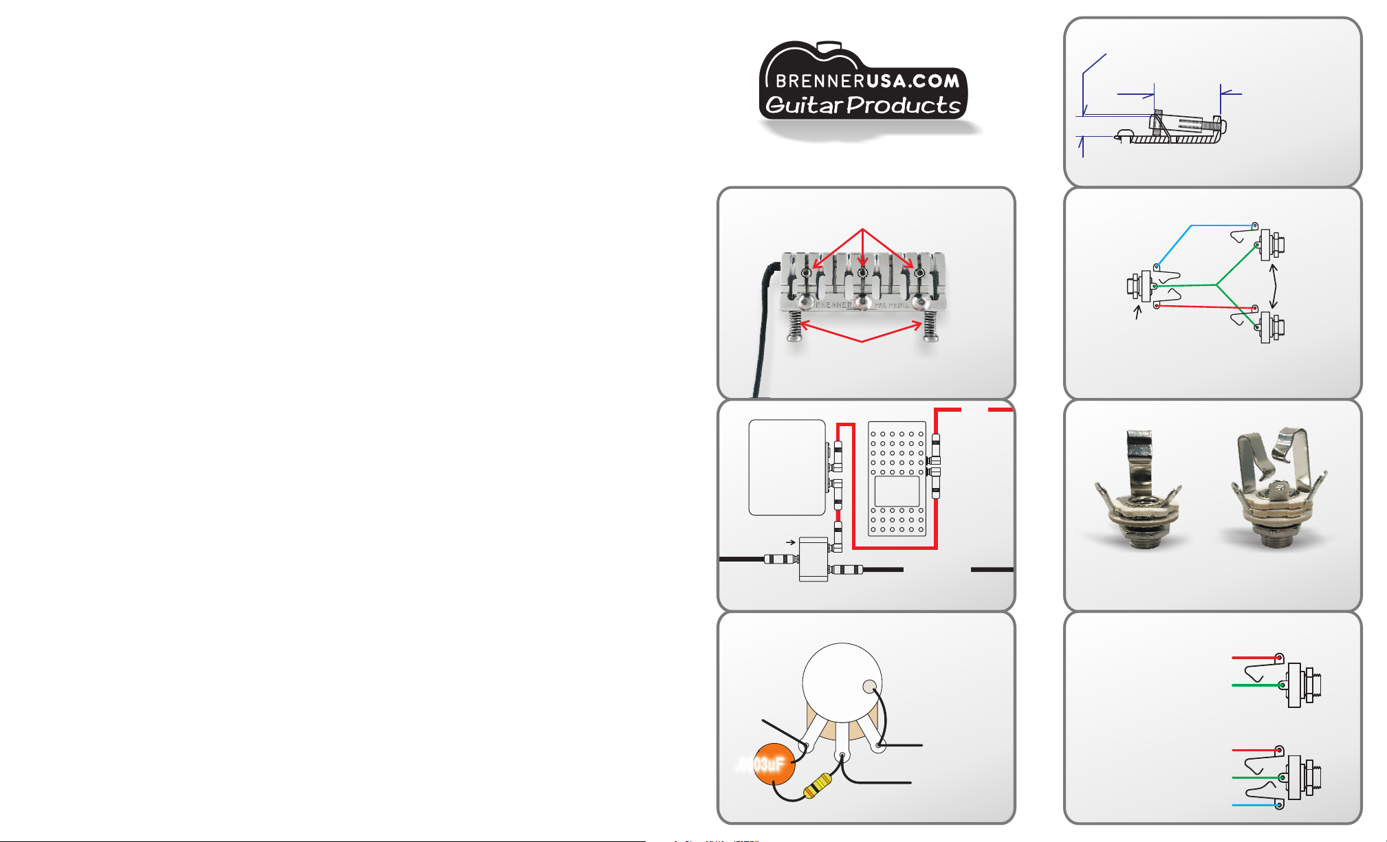
INTONATION
REFERENCE
PIEZO
SIGNAL
STEREO
SIGNAL TS JACKS
S P L I T T E R S C H E M A T I C
MAGNETIC
SIGNAL
TRS JACK
TS JACK
(tip-sleeve)
TRS JACK
(tip-ring-sleeve)
T S J A C K
T R S J A C K
MAGNETIC SIG.
GROUND
MAGNETIC SIG.
GROUND
PIEZO SIG.
Onboard Guitar Passive
Volume Control With
Treble Bleed For Use
With PIEZO-PRO-V
(OPTIONAL)
300K
500K
.0003uF
Piezo Signal
Wire
To Stereo Jack
Ring Connector
To Ground
H E I G H T A D J U S T M E N T
S E T S C R E W S
I N T O N AT I O N
A D J U S T M E N T
S C R E W S
T Y P I C A L S I G N A L C H A I N
MAGNETIC SIGNAL
TO AMP
PIEZO
SIGNAL TO PA
VOLUME
PEDAL
PIEZO
PREAMP
STEREO
SPLITTER
Measure and note the distance from the back of the bridge to the outer
string intonation points (string /saddle contact point at the front of each
saddle). Remove string saddles. See WIRE GUIDE FOR TELE
BRIDGE/PICKUP ASSEMBLY on backside if applicable. Install P1-1
saddle using two intonation screws and springs provided. Piezo-one
saddles are equipped with three height adjusting set screws. String
height should be established using outer set screws while center screw
is backed off. The center screw is provided for center support after
height is established. Adjust intonation and height screws to properly
position the piezo-one saddle to previously noted dimensions. Remove
and notch the underside of pickguard or pickup ring to contain the piezo
pickup wire between it and the guitar body (refer to pictures). You may
prefer to save the integrity of original parts and purchase a replacement
ring or pickguard for this purpose. Run the piezo wire to the location of
the guitar output jack. Remove the jack in order to transfer wires to new
jack as follows:
Identify and note colors of magnetic pickup signal wire (attached to the
jack "tip" connector), and ground wire (attached to the jack "sleeve"
connector) on existing TS jack. Connect these wires to corresponding
"tip" and "sleeve" connectors on the new stereo TRS jack supplied. The
piezo output wire is a coax type cable with a center signal wire
separated from a surrounding braided shielding wire. The plug end is
used in some onboard preamp installations, and factory testing. Cut the
plug end off and strip the wire for solder connection. The piezo cable's
outer shield wire automatically connects to ground when the saddle is
mounted on a metal bridge plate that has been grounded (typical for
operation of most electric guitars). Grounding can be testing between
the bridge plate and jack sleeve (ground) tab with continuity tester or
multimeter. The piezo pickup's shield wire may be combined with the
guitar jack's ground connection, but this may result in noise or "hum"
from a ground loop condition. The piezo pickup's shield wire must be
connected to the jack's "sleeve" connection for installation on
instruments with non-metallic bridges, or on instruments without
magnetic pickups. The shield wire can be peeled back a bit, and
covered with shrink tube or electrical tape in most cases. The piezo
signal wire should be connected to the "ring" connector on the TRS
jack*. Install the jack (and plate) on the guitar. Insert an audio cable
plug into the jack to insure that it is able to go in all the way. On some
Strat style jack plates - the stereo jack may be slightly longer and cause
the plug tip connector to hit the wood. If this happens, try rotating the
jack to a new position. If this doesn't solve the problem, It may be
necessary to carve some wood at the point of obstruction. Replace the
pickguard and/or electronics cover. Install strings. Recheck noted
dimensions and make sure center height screw is snug for support only.
The guitar will now function as before with a mono cable inserted -
magnetic pickup(s) only. With a stereo cord inserted, the guitar outputs
magnetic signal through the tip, and piezo signal through the ring of the
stereo plug.
* the piezo signal wire can be connected to the jack’s “tip”connector for
guitars with piezo only (including nylon string guitars).
Stratocaster, Strat, and Telecaster are a trademarks of Fender
Musical Instruments Corp. Brenner Guitar Products is in no way
affiliated with Fender Musical Instruments Corp.
P1-1 Saddle Operation:
Brenner piezo-one™gang guitar saddles are designed for simple,
reversible installation that is non-destructive to the instrument. The design
features string supports that are machined for maximum sonic
engagement with the piezo elements. This electro-mechanical
arrangement produces a stronger output, frequency response, and
dynamic range in comparison to other piezoelectric transducer saddles.
Machined-in compensation is optimized for both intonation and low action
when using commonly incremented "unwound G" string sets. The saddles
are compatible with all preamplifiers designed for piezo transducer use.
The P1-1 models are a direct replacement for “modern" saddles common
to Stratocaster, and many Telecaster guitars. The P1-1A configuration
features overall compensation adjustment screws located to fit bridge
plates with 2-1/16 inch (52.5mm) string spacing. The P1-1B features
screw locations spaced for plates having 2-1/8" (54mm) spacing. Caution:
Fender has equipped some guitar models with “offset”modern saddle
bridges. Offset saddles feature compensation screws that are off center
with the saddle. A common centered style Fender or compatible
aftermarket bridge plate is required for piezo-one installation on guitars
equipped with offset bridges.
Piezo transducers have very high impedance, and produce very little
current. Passive volume/tone controls degrade the signal with resistive
losses and capacitance. It is for this reason that the best piezo transducer
systems implement a preamplifier stage followed by volume/tone control.
Some onboard preamps are capable of blending piezo and magnetic
signals in both mono and stereo modes. Blended mono output combines
magnetic and piezo sound into one signal. The best sounds will always
be produced in stereo mode with magnetic pickups sent to a conventional
guitar amp, and piezo signal routed to an acoustic amp or PA system
having 2 or 3 way speakers. A stereo cable is typically used to output
both signals from the instrument. The cable's plug tip and ring will carry
the magnetic and piezo signals respectively. A stereo splitter optimally
separates the signals into two mono outputs for guitar amp, and full range
system.
Our outboard PIEZO-PRO-V preamp/splitter/vol-control unit combines
piezo preamplifier, signal splitter, and post-preamp volume control into one
stage friendly device. Blend signals much faster by using existing guitar
control with PIEZO-PRO-V foot control. The PIEZO-PRO-V eliminates the
need to install onboard piezo preamps in each guitar or alter existing
pickup wiring.
It is possible to add passive volume control to the instrument, but some
tone and signal loss will occur as mentioned previously. Signal
degradation can be minimized by selecting components that best match
the input impedance of the piezo preamplifier. A .0003 mf capacitor and
300K ohm resistor series wired across the input and output lugs of a 500K
potentiometer work nicely with the PIEZO-PRO-V (volume treble bleed
circuit). Components will vary for optimal sound with other preamps.
Stacked or concentric potentiometers offer a great solution for adding
piezo volume control without the need to drill additional holes into the
instrument.
The following instruction describes piezo-one™installation for
magnetic/piezo hybrid guitar without passive control or onboard preamp.
If choosing to install an onboard preamp, refer to the manufacturer's
documentation for additional steps.
Installation:
The BrennerUSA site includes a gallery of photos that may help in
planning installation. Remove strings. Measure and note dimensions of
outermost saddles (guitar high E, and low E string saddles) for height
above the bridge plate.

Guitar Products
piezo-o n e ™ P1-1
• OPERATION AND INSTALLATION GUIDE •
Guitar Products
®
MILWAUKEE, WISCONSIN
P1-2 SADDLES FOR
TELECASTER
ASHTRAY BRIDGES
ALSO AVAILABLE
Stratocaster, Strat, and Telecaster
are a trademarks of
Fender Musical Instruments Corp.
Brenner Guitar Products
is in no way affiliated with
Fender Musical Instruments Corp.
P I E Z O P R E A M P - S I G N A L S P L I T T E R - V O L U M E P E D A L
all in one compact unit.
NO NEED TO PUT A PIEZO PREAMP IN EACH OF YOUR GUITARS
-
RECOMMENDED CONNECTIONS:
STEREO IN - Magnetic and Piezo pickups from guitar
MAGNETIC OUT - Magnetic pickup signal to guitar amp
PIEZO OUT - Piezo signal to acoustic amp or PA system
Stereo Input Jack - magnetic pickup signal on "tip" - piezo pickup signal on "ring"
- Stereo Input Jack Switch - preamp powers up when a stereo cable is inserted
- Outputs (2) - mono magnetic pickup signal - mono piezo preamp out
- Four Band EQ / Volume Section
- Master Foot Dial Volume Control
- Battery Check Button
- Dimensions 3-3/8" W x 6-1/4" L x 2-3/16" H
- Switching 9VDC 2.1mm Barrel Jack - disconnects battery when using a power
supply (standard "negative center" type)
WIRE GUIDE FOR TELE BRIDGE/PICKUP ASSEMBLY
Identify magnetic bridge pickup height adjustment screw for wire guide
installation. Place wire guide nearby. While holding the magnetic bridge
pickup in position, remove the screw. This will keep spring in position
under the plate. Put wire guide on screw and reinstall as pictured.
Remove the bridge assembly. Pull up on the magnetic pickup to raises
screw heads and wire guide for easy wire installation. Thead piezo wire
through the slot underneath the wire guide and through the pickup hole
along side the of the magnetic pickup. Pull the wire through leaving
slack for proper saddle position and adjustment. Adjust magnetic pickup
height adjustment screws and wire guide as desired.
P I E Z O - P R O - V P R E A M P
Popular Accessories For Musical Instruments manuals by other brands

Fishman
Fishman FLUENCE SIGNATURE RICHARD Z Series installation guide

Auralex Acoustics
Auralex Acoustics Deep6 Installation & user guide

K&K Sound
K&K Sound PURE FLOATING BRIDGE product manual

Roland
Roland V-Drums MDS-25 owner's manual

Wenger
Wenger Maestro Acoustical Tower installation instructions

Duncan
Duncan Vintage for Jazzmaster SJM-1 Wiring diagram


