Konig & Meyer 18944 User manual

SICHERHEITSHINWEISE
- Bitte beachten Sie die Angaben dieser Aufstellanleitung
- Ebenfalls zu beachten sind die Sicherheitsanweisungen
-und Aufbauanleitungen der verwendeten Keyboardständer
- Zunächst Sichtprüfung vornehmen, ob der Universalhalter
-vollständig und soweit erkennbar in Ordnung ist.
- Beschädigte Teile dürfen nicht weiterverwendet werden.
- Wir empfehlen das Standrohr stets senkrecht zu montieren.
-Diese Stellung ist am schonendsten und sichersten.
-Die Stirnverzahnung der Rastschelle ermöglicht einfache
-Korrekturen, z.B. nach Verstellungen des X-Keyboardständers.
- Auf feste Schraubverbindungen der beteiligten Artikel achten
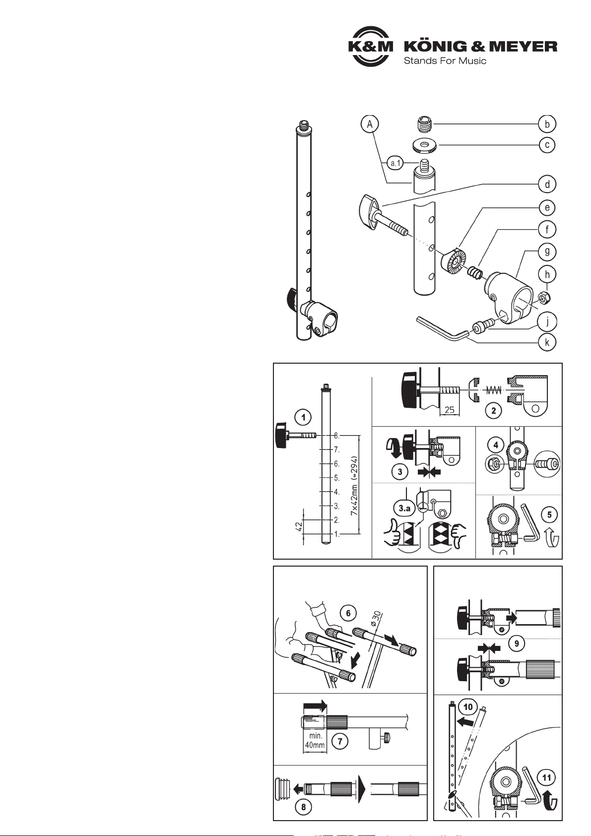
BESTANDTEILE - ÜBERSICHT (A-k)
AStandrohr ø 25 x 450 mm mit
a.1 Gewindebolzen 3/8“.
Im Zubehörbeutel:
bReduziergewinde 5/8“,
cAlu-Rändelscheibe 3/8“,
dKlemmschraube M8 x 50 mm,
eRastscheibe,
fDruckfeder,
gRastschelle,
hSicherungsmutter M8,
jZylinderschraube M8 x 20 mm,
kInbusschlüssel SW6.
BESTANDTEILE MONTIEREN (1-5)
1Klemmschraube ddurch eine der 8 vorhandenen
1Bohrungen des Standrohres stecken - unter
1Berücksichtigung der gewünschten Höhe
2Aus dem Rohr ragt nun der Gewindebolzen (25 mm)
2Darüber werden geschoben: die Rastscheibe esowie
2die Druckfeder f
3Anschließend wird die Klemmschraube in das Innen-
3gewinde der Rastschelle ggedreht - bis zum Anschlag
3.a BEACHTE: die Stirnverzahnungen von Rastscheibe
3.a und Rastschelle dürfen nicht Spitze auf Spitze stehen,
3.a sondern müssen stets ineinandergreifen.
4Die Sicherungsmutter hwird in eine der beiden
4sechskantförmigen Aussparungen der Rastschelle eingelegt
5Die Zylinderschraube jvon der anderen Seite durchstecken
5und nur leicht mit der Sicherungsmutter verschrauben
MONTAGE am KEYBOARDSTÄNDER (6-11)
Voraussetzung ist ein Stativ mit Auflagerohr ø 30 x 350 mm: siehe
K&M X-Keyboardständer 18930, 18933, 18940, 18990 und 18995.
A. Keyboardständer vorbereiten:
6Keyboardständer in Gebrauchslage aufstellen (Höhe, Breite)
7Gummi am Auflagerohr nach innen schieben: mind. 40 mm tief
8Abschlußkappe entfernen
B. Universalhalter befestigen
19Rastschelle über das Auflagerohr schieben - bis zum Anschlag
10 Standrohr in senkrechte Lage drehen
11 Rastschelle auf dem Auflagerohr sicher befestigen durch festes
11 Anziehen der eingelegten Zylinderschraube M8 x 20 mm
AUFSTELLANLEITUNG
18944 Universalhalter
- Passt an alle X-Keyboardständer mit 30 mm Auflagerohr
- Besonders zu empfehlen für K&M-Modelle mit 350 mm Auflagentiefe:
-18930, 18990 (Hebelbedienung) sowie 18940, 18995 (Rastknopf).
- Ermöglicht den Ausbau des Keyboardstativs mit: Notenpultplatte,
-Schwenkarm, Schwanenhals. iPad-Halter, Tablet-PC- Halter etc.
- Anschlußgewinde 3/8" inklusive 5/8“-Adapter
- 8-fach höhenverstellbar in Schritten zu 42 mm
Vielen Dank, dass Sie sich für dieses Produkt entschieden haben. Diese
Anleitung informiert Sie über alle wichtigen Schritte bei Aufbau und Hand-
habung. Wir empfehlen, sie auch für den späteren Gebrauch aufzubewahren.
KÖNIG & MEYER GmbH & Co. KG
Kiesweg 2, 97877 Wertheim, www.k-m.de
18944-000-55 Rev.04 03-80-326-00 5/18
BESTANDTEILE - ÜBERSICHT
BESTANDTEILE MONTIEREN
MONTAGE am KEYBOARDSTÄNDER
A. Keyboardständer vorbereiten B. Universalhalter befestigen

BENUTZERHINWEISE/FUNKTIONEN
INSTANDHALTEN, REINIGEN
- bei Wartungsarbeiten zuvor Traglasten entnehmen
- stets auf evtl. Gefährdungen achten - z.B. die Gefahr des
-Einklemmens bei beweglichen Teilen
- zur Reinigung ein leicht feuchtes Tuch und sanftes
-Reinigungsmittel benutzen
FEHLERSUCHE (F) und BESEITIGUNG (B)
F: Universalhalter wackelt:
F: B: Standrohr ist nicht fest genug mit der Rastschelle
F: B: verschraubt 3
F: B: Stirnverzahnung zwischen Schelle und Scheibe greift nicht
F: B: richtig ineinander 3.a
F: B: Rastschelle sitzt zu locker auf dem Stativ-Auflagearm 11
F: B: Keyboardstativ wackelt (wg. Untergrund, Stativzustand, etc.)
F: Traglast wackelt:
F: B: Verschraubung zwischen Anschlußgewinde und Traglast
F: B: prüfen
F: B: Traglast prüfen
ANSCHLUSSGEWINDE
12 Fest installiert: 3/8" mitsamt passender Rändelscheibe
13 Zusatzadapter für 5/8" - bei Bedarf auf 3/8" geschraubt
TYPISCHE ANBAUPRODUKTE / TRAGLASTEN
14 Notenpultplatte,
15 iPad-Stativhalter
16 Tablet-PC-Stativhalter
17 Schwanenhals
18 Schwenkarm
EINSTELLMÖGLICHKEITEN
Wir empfehlen vor dem Verstellen des Universalhalters ggf.
wertvolle Traglasten entfernen (z.B. Tablets).
19 HÖHE
19 a. Standrohr festhalten, Klemmschraube vollständig aus der
19 a. Rastschelle herausschrauben, wobei die Rastscheibe und
19 a. die Feder auf dem Gewindebolzen verbleiben.
19 b. Gewünschte Bohrung des Standrohres (8x) wählen und
19 b. mittels Klemmschraube wieder an Rastschelle befestigen.
19 c. Die 8 Stufen im Abstand von 42 mm ermöglichen eine
19 c. Höheneinstellung von 120 bis 415 mm.
20 SEITLICHE NEIGUNG
20 a. Das Standrohr sollte immer möglichst senkrecht stehen.
20 b. Verstellungen am X-Stativ ändern den Winkel des Stand-
20 b. rohres und erfordern eine Korrektur.
20 c. Das Standrohr kann mittels der Stirnverzahnung von Rast-
20 c. schelle und -scheibe ringsum in Stufen zu 8° verstellt werden.
20 d. Standrohr festhalten, Klemmschraube etwas lösen bis die
20 d. Verzahnung sich nicht mehr im Eingriff befindet, Standrohr in
20 d. gewünschte Position bringen und Klemmschraube festziehen.
20 e. Die 8°-Stufen der Stirnverzahnung können das Standrohr um
20 e. bis zu 4° schräg stehen lassen. Korrigiert werden kann dies
20 e. durch die Justierung der Rastschelle:
20 e. Schraube lösen - Schelle ausrichten - Schraube anziehen.
21 TRANSPORT- / PACKSTÜCK
21 Das Halterohr kann zu diesem Zweck platzsparend nach
21 unten weggeklappt werden: Vorgang siehe Kap. 20.d.
TECHNISCHE DATEN / SPEZIFIKATIONEN
Material
Standrohr: Stahl, gepulvert, schwarz
Rastschelle und Rastscheibe: Zinkguß,
gepulvert, schwarz
Gewinde: Stahl, verzinkt
Griff, Kappe: Kunststoff PA, PE, schwarz
Traglast Notenpultplatte, Schwenkarm, Schwanenhals,
iPad-Halter, Tablet-PC-Halter, etc.
Abmessungen ø 25 x 450 mm, Höhe: 125-420 mm in 8 Stufen,
3/8" und 5/8"
Verpackung Karton: 580 x 80 x 50 mm
Gewicht 0,7 kg
ANSCHLUSSGEWINDE
HÖHE
TRANSPORT- / PACKSTÜCK
SEITLICHE
NEIGUNG
ANBAUPRODUKTE / TRAGLASTEN

SAFETY NOTES
- Please consider the information provided in the setup instructions
- Also consider the safety and assembly instructions of the keyboard
-stand
- First perform a visual inspection, to determine if the universal holder
-is complete and to the extent possible in working order.
- Damaged parts may not be used again.
- We recommend that the stand tube is always mounted vertically.
-This position is the safest and has the least strain.
-The back gears of the locking bracket provide
-for easy corrections e.g. after adjusting the X-keyboard stand.
- Ensure that the screws are tight for all of the involved products
COMPONENTS - OVERVIEW (A-k)
AStand tube ø 25 x 450 mm with
a.1 Threaded bolt 3/8".
Accessory bag:
bThread adapter 5/8",
cAluminum knurled washer 3/8",
dClamping knob M8 x 50 mm,
eLocking disk,
fSpring,
gSnap-in bracket,
hLocking nut M8,
jSocket head screw M8 x 20 mm,
kAllen wrench / hexagon key SW6.
MOUNTING OF COMPONENTS (1-5)
1Place Clamping knob dthrough one of the 8 existing
1drill holes on the stand tube - under consideration of the
1desired placement
2The threaded bolt (25 mm) projects out of the tube.
2The lock disk eand the spring fare placed on the threaded bolt
3Then the clamping knob is placed into the internal thread of
3- of the snap-in bracket g- as far as it will go
3.a NOTE: the back gear of the locking disk
3.a and Snap-in bracket must be aligned properly,
3.a as to avoid the grinding of the teeth
4The locking nut his placed in one of the hexagon
4recesses of the Snap-in bracket
5The Socket head screw jis placed from the other side
5and is screwed into the Locking nut - be sure not be screw
5it in too tightly
MOUNTING to the KEYBOARD STAND (6-11)
Prerequisite for the stand with support tube ø 30 x 350 mm: please
refer to K&M X-Keyboard Stands 18930, 18933, 18940, 18990 and
18995.
A. Prepare the keyboard stand:
6Setup the keyboard stand so that it is ready for use (Height, Width)
7Place the rubber into the support tube at least 40 mm deep
8Remove the cap
B. Attach the universal holder
19Place the snap-in bracket over the support tube as far as it will go
10 Place the stand tube in a vertical position
11 Secure the snap-in bracket to the support tube and tighten
11 the recessed socket head screw M8 x 20 mm
SETUP INSTRUCTIONS
18944 Universal holder
- Universal holder for all X-Keyboard stands with 30 mm support tube arm
- Recommended for K&M Models with 350 mm depth:
-18930, 18990 (Lever operation) as well as 18940, 18995 (locking knob).
- Enable the expansion of the keyboard stand with: Music desk
-swivel arm, swan neck, iPad Holder, Tablet PC Holder etc.
- 3/8"-connection thread including 5/8" adapter
- 8 height adjustments in 42 mm intervals
Thank you for choosing this product. The instructions provide directions
to all of the important set up and handling steps. We recommend you
keep these instructions for future reference.
KÖNIG & MEYER GmbH & Co. KG
Kiesweg 2, 97877 Wertheim, www.k-m.de
18944-000-55 Rev.04 03-80-326-00 5/18
COMPONENTS - OVERVIEW
MOUNTING OF COMPONENTS
MOUNTING to the KEYBOARD STAND
A. Prepare the keyboard stand B. Attach the universal holder

USAGE NOTES / FUNCTION
MAINTENANCE, CLEANING
- in the case of maintenance work remove any equipment first.
- always be aware of potential risks, e.g. danger of pinching or
-wedging fingers in case of moving parts.
- to care for the product, use a damp cloth and non-abrasive
-cleaning agen
FAULT-FINDING (F) and REPAIR (R)
F: Universal holder is not stable:
F: B: The stand tube is not properly screwed into the
F: B: snap-in bracket 3
F: B: Back gear between the bracket and disk are not
F: B: engaged properly 3.a
F: B: The snap-in bracket is loose on the stand support arm 11
F: B: The keyboard stand is not stable (due to surface, stand
F: B: condition, etc.)
F: The equipment is not stable:
F: B: Check the connection between the connection thread
F: B: and the equipment
F: B: Check the equipment
CONNECTOR THREAD
12 Install securely: 3/8" with the suitable knurled washer
13 Additional adapter for 5/8" - if needed screw onto 3/8"
TYPICAL ANCILLARY PRODUCTS / WEIGHT BEARING LOADS
14 Music desk,
15 iPad stand holder
16 Tablet PC stand holder
17 Gooseneck
18 Boom arm
ADJUSTMENT OPTIONS
We recommend prior to the adjustment of the universal holder
that valuable equipment be removed (e.g. Tablet).
19 HEIGHT
19 a. Hold the stand tube, unscrew and remove the clamping
19 a. knob from the snap-in bracket, the locking disk
19 a. and spring remain on the threaded bolt.
19 b. Select the desired drill hole on the stand tube (8x) and
19 b. using the clamping knob place the snap-in bracket back
19 b. on the support tube.
19 c. The 8 levels in 42 mm intervals provide for height
19 c. adjustments from 120 to 415 mm.
20 SIDE ANGLE
20 a. The stand tube should always be in a vertical position.
20 b. Adjustments to the X-Stand change the angle of the stand
20 b. tube and requires adjustments to be performed.
20 c. The stand tube can be adjusted with the back gear of the
20 c. locking pin and disk in 8° steps.
20 d. Hold the stand tube, loosen the Clamping knob a bit until
20 d. the teeth are no longer engaged, place the stand tube in
20 d. the desired position and tighten the Clamping knob.
20 e. The 8°- levels of the back gear can result in the stand tube
20 e. being tilted up to 4°. This can be corrected through adjusting
20 e. the snap-in bracket:
20 e. Loosen the screw - adjust the bracket - tighten the screw.
21 TRANSPORT / PACKAGING
21 The holding tube can be collapsed and folded with a small
21 footprint. Procedure please refer to Section 20.d.
TECHNICAL DATA
Material
Stand tube: Steel, powder coating, black
Snap-in bracket and locking disk: Zinc die-cast,
powder coating, black
Thread: Steel, galvanized
Handles, caps: Plastic, PA, PE, black
Load Music desk, boom arm, gooseneck, iPad stand
holder, Tablet PC stand holder, etc.
Dimensions ø 25 x 450 mm, Height: 125-420 mm
in 8 levels, 3/8" and 5/8"
Packaging Box: 580 x 80 x 50 mm
Weight 0.7 kg
CONNECTOR THREAD
ANCILLARY PRODUCTS / WEIGHT BEARING LOADS
HEIGHT
TRANSPORT / PACKAGING
SIDE ANGLE
Table of contents
Languages:
Other Konig & Meyer Accessories For Musical Instruments manuals

Konig & Meyer
Konig & Meyer 18874 User manual

Konig & Meyer
Konig & Meyer 15010 User manual

Konig & Meyer
Konig & Meyer 18806 User manual

Konig & Meyer
Konig & Meyer 18804 User manual

Konig & Meyer
Konig & Meyer 12170 User manual

Konig & Meyer
Konig & Meyer 12384 User manual

Konig & Meyer
Konig & Meyer Spider Pro 18876 User manual

Konig & Meyer
Konig & Meyer Ring Lock User manual