BREWHA Equipment Co Ltd. BIAC User manual


BREWHA Equipment Co Ltd. www.brewhaequipment.com
BREWHA BIAC User Manual
Dear Customer,
We are delighted that you have chosen a BREWHA BIAC for your brewing system! We trust that
it will bring you many fun-lled hours of brewing, and of course, many times spent enjoying the
fruit of your craft with your friends, family and/or customers.
This manual provides information on installation and setup, and its intent is to have you
enjoying brewing with your BIAC as quickly, safely, and condently as possible—please take the
time to read it carefully. The manual is organized into sections, identied by the numbered (and
colored) tab on the edge of the page to help you nd information easily:
1. The red section discusses
safety.
2. The orange section discusses
installation.
3. The yellow section discusses
brewing.
(For the following sections, view the digital copy, available on the website.)
4. The green section has
recipes.
5. The blue section is for warranty and returns
.
6. The indigo section discusses
privacy and terms of service.
In addition to the information in this manual, the ‘Learn’ section of the website contains lots of
videos and up-to-date information organized into categories at the top of the page, and each
website page contains a search bar that can help you nd what you are looking for quickly.
Sincerely,
BREWHA Equipment Co
1
2
3
4
5
6

WARNING!!
While BREWHA designs its systems with safety as a primary concern, always keep the
following in mind:
1. These vessels are not designed to withstand more than 3psi pressure in the 3-in-1
fermenter (14.9psi in the 4-in-1 fermenter) and 5psi in the 3-in-1 fermenter jacket (7psi
in the 4-in-1 jackets). Since tap water is often supplied at over 60psi, care needs to be
taken when using tap water to not allow the pressure to exceed the design allowance.
BREWHA will not be held responsible for deformation to the vessels due to pressure or
vacuum (do not let a vacuum occur).
2. The magnetic drive centrifugal pumps we supply are not designed to be ran empty
and should only be ran full of liquid; in addition, the exit should never be fully closed
while running or the pump may overheat and be damaged; damage due to improper
operation is not covered by warranty.
3. Immersion heating elements are not designed to be heated without water or they
will overheat and could be ruined; during mash, the pump outow (returning wort
from the bottom of the fermenter to the top of the Mash Colander) will very likely need
to be throttled/slowed with a valve (either on the exit port of the pump or the return
port on the Mash Colander), so that the pump does not remove water from around the
elements faster than it is replenished from the Colander above (see recirculation rate
recomendations in the Brewing section of this manual).
4. Electrical devices (including the power controller, heating elements, sensors,
solenoid, pump, etc.) can be extremely dangerous, and electrical systems need to
be handled with extreme care. Always unplug the devices any time maintenance is
required or the system is not in use. Some devices such as the Power Controller may
have multiple power sources and all sources should be unplugged before servicing.
For added safety, a GFI/GFCI can be installed on the source power for the brewing
equipment and an electrician consulted for all electrical installations.
5. Contents of brewing vessels and hoses may be hot and/or under pressure so use
extreme caution.
6. To reduce any risk of damage or harm, the vessels should only be moved when
empty or secured against tipping; always move them with caution and only on smooth,
level, concrete oors.
7. Lifting the Mash Colander out can be dangerous, so ensure there is a properly
engineered lifting device installed. Never operate beneath the Colander when it is
suspended.
8. Check our suppliers’ manuals for further safety information.
2
Safety

2
Safety
1
2
3
4
5
6
Safety
Table of Contents
Installing a ground fault interrupter ...... 4
Electric heating elements ...... 5
Use of a pressure and vacuum relief valve to prevent pressure build up ...... 8
Preventing damage to vessel jackets ...... 9
Securing sanitary clamps against accidental loosening ..... 10
If you have any questions about how to reduce the risk of harm, do not hesitate to
For additional information on safety, consult manufacturer’s manuals, as well as the
‘Safety’ category at the top of the ‘Learn’ page on the website:
https://brewhaequipment.com/blogs/howtobrewbeer/tagged/safety
3
4
BIAC User Manual Safety
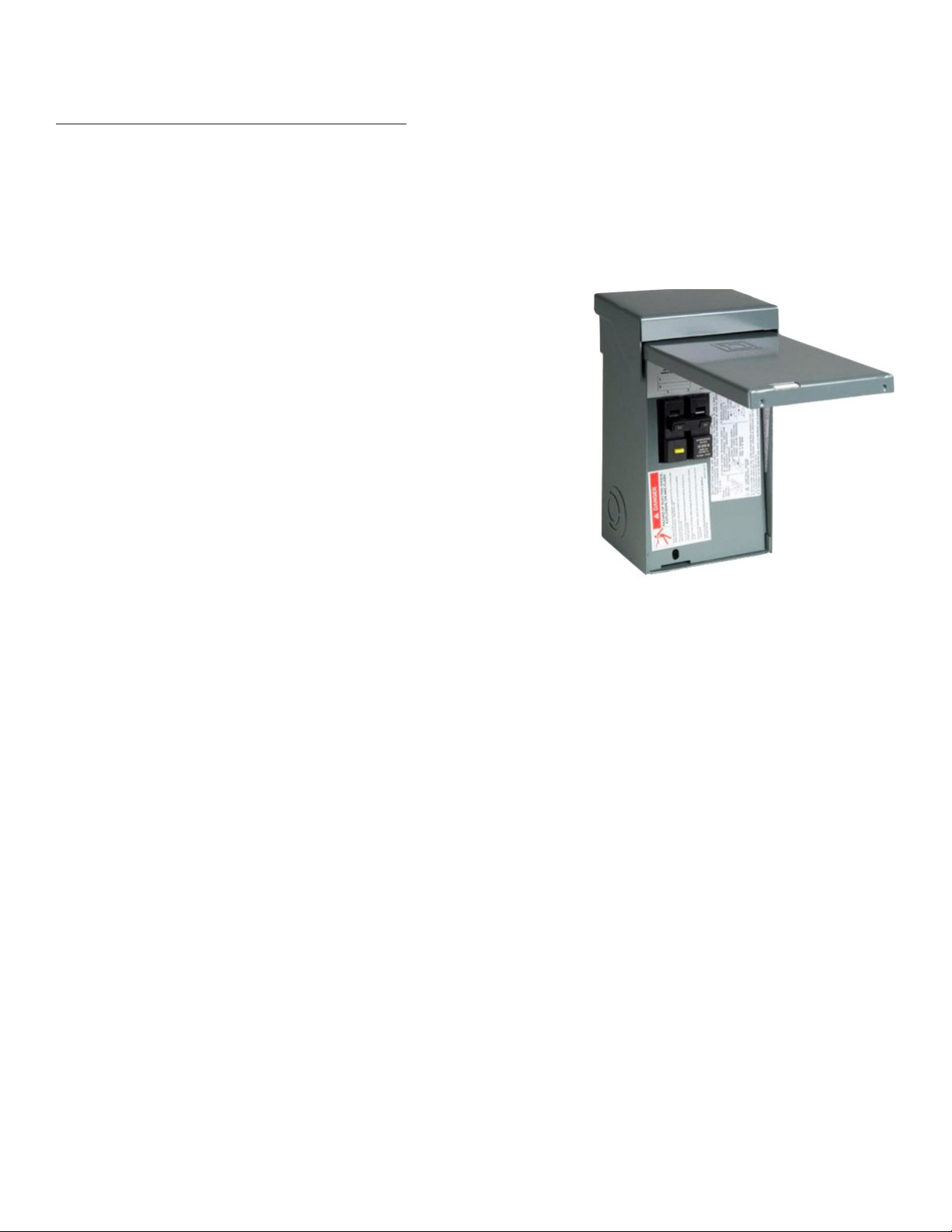
Installing a Ground Fault Interrupters
BREWHA recommends that brewers consider having a GFCI/GFI (Ground Fault Circuit
Interrupter) installed on their power supply.
While most electrical panels will have fuses or breakers, they do not often have a GFI. Breaker
boxes (the electrical panel often found in laundry rooms) will prevent too much overdraw, but a
GFI will respond much faster than a breaker or fuse to any deviation in electrical current.
A GFI can be installed in an existing breaker box (if not
already there), or one can be added on the line that services
your brewing setup. For home brewing systems, GFI panels
that service outdoor spas/hot tubs (240V/40A) are available at
Home Depot, Amazon or other electrical or hardware stores
and are relatively inexpensive.
(*Some portable GFIs that are installed inbetween the
Power Controller and a heating element do not work with
the BREWHA Power Controller at <100% power output
as the power output reduction causes the GFI to trip. It is
recommended to use a wall-mounted GFI installed prior to
the Power Controller.)
For commercial installations, consult a qualied electrician
for their recommendation on whether a GFI is necessary.
Figure 1

Electric Heating Elements
Immersion water heating elements must always be
completely immersed in water when operated to
ensure that heat is quickly dissipated. If the element is
not fully immersed, it could overheat and melt. Many
brewers have brewed hundreds of batches of beer
without a single failure, but if it does occur, melting a
heating element by ‘dry-ring’ is not a fun experience.
It could also ruin the batch. When they fail, elements
sometimes have complete external failure (shown in
Figure 2) or just fail internally as is often evidenced by
a heat discoloration on the element (shown in Figure
3). Having a backup replacement element will come
in handy if your element ever fails, but here are a few
suggestions on how to help avoid failure in the rst
place.
The most common period of failure is while
recirculating during mashing and/or vorlauf. In the
BIAC, wort from the Mash Colander drains into the
fermenter, and the pump pulls this wort out the
bottom of the fermenter and returns it above the
grain in the Mash Colander. This is useful for vorlauf
and for regulating mash temperature because the
wort can be heated as it exits the Mash Colander,
passes the heating element, and returns to the top
of the grain bed. It is possible, however, if the pump
is operating too fast, to get ahead of the grain bed
ow rate and pump all the wort out of the area
under the Mash Colander where the heating element
is situated. This could remove all the water from
around the element and, if the element is red
at that point, lead to ‘dry ring’ of the element
and burn out. This is most likely to happen if there is a ‘stuck mash’ where wort
does not freely ow down through the grain. A stuck mash could happen at any
time during the mash, but is most likely to occur in the early stage of the mash,
especially if the grain crush is particularly ne. There are a few things that can be
done to help prevent a stuck mash.
First, increase the crush size for your grain by adjusting your roller width (or have
4
BIAC User Manual Safety
1
2
3
4
5
6
5
Warning: heating elements must always be completely
immersed in water.
Figure 2
Figure 3

your supplier do it for you). A general width guideline is 0.04–0.048”/1–1.2mm. If you still have
a problem, go slightly wider. If you are experimenting with gelatinous or gummy cereals (e.g.,
oats or rye), you can include rice hulls to help counteract the ‘gummy’ eect and keep the bed
uid. Also, using a good grain mill to crush your grain evenly is important. We recommend the
Crankandstein 328G (fully geared 3-roller mill) and have found the factory setting (0.045”) to
provide a good size for uidity and conversion.
Second, when doing a single-step mash, if the strike temperature is properly calculated, it is
not critical to pump the wort during mash and it can be simpler not to. With the Mash Colander
inserted in the fermenter, it is eectively surrounded by a water bath that will help maintain the
temperature. The element keeps the water bath at the target temp for mashing and warms the
colander, which warms the mash. When mashing is almost complete, the pump can be operated
to move the water under the colander to the top of the grain bed for vorlauf. While care still
needs to be taken, during vorlauf it is less likely that your mash will stick or that you will run out
of water in the cone portion of the fermenter where the element is, especially if the next step is
followed.
Third, if circulating during the mash or during vorlauf, if the water level starts to rise in the
Colander, it means wort is being pumped out of the bottom faster than it is being replenished,
and the pump outow should be slowed (in time, if the ow is not slowed, the element will be
exposed and could be damaged). To prevent the pump from moving wort too quickly, a valve
must be installed on the downstream side of the pump (either on the pump outlet or on the
Mash Colander port) and partially close it to slow the amount of wort being circulated. (Don’t
close or restrict a valve BEFORE the pump in any way, as this ‘starves’ the pump and can damage
it.) If grain that has fallen through the Colander plugs the pump line, momentarily open the valve
wide to move the grain into the Mash Colander or attach the pump intake line to the cone side-
racking port, rather than the bottom port of the fermenter (although if possible, it is better for
uniform ow through the Colander to keep the pump line connected to the bottom port).
Fourth, with the Power Controller, power output can be set to around 20-30% during mash,
which is typically more than enough to maintain mash temperature while minimizing the chance
that the element will be ruined if temporarily exposed.
Note 1: Throttling the pump (by partially closing a downstream valve) is also the best way to
prevent pump cavitation. Cavitation occurs when the pump is pushing liquid out faster than it
can draw it in. This creates a vacuum, which causes a ‘cavity’ to form, which prevents ecient
operating of the pump (a screeching sound from the pump is most often caused by cavitation).
When the ow is throttled back on the exit side by partially closing a valve, it prevents liquid
from being pushed out faster than it can be drawn in, preventing the cavity from forming.
6
BIAC User Manual Safety
Caution: A ‘squealing’ sound in the pump often indicates a cavity, in which
case the pump should be turned o immediately. See more information in
‘Installation’ section.

6
BIAC User Manual Safety
1
2
3
4
5
6
Note 2: When brewing low-volume batches, it is also important to be careful that
the element is not exposed during the boil. To ensure that the water level will not
drop to the point where the element is exposed, during lling you need to rst
observe/calculate the volume at which the element is fully covered (approximately
20% of the total volume of the fermenter). Then add 10-20% volume as a safety
buer, and have this as your minimum water/wort level in the vessel. Then check
all of your recipes and ensure that at no point during heating will the volume level
ever be below this. And it is always best practice to never be too far from your
equipment on brew day. There have been reports of customers leaving during the
boil to run a few errands and returning to nd their element dry-red and ruined.
Note 3: The same rules apply during fermentation as during mash and boil—keep
the element covered with water at all times. When using the element to keep the
beer warm during fermentation, it is important to keep the power output on the
Power Controller set to less than 3% to ensure that yeast that sticks to the element
does not scorch. This will also likely prevent dry-ring the element, as at such low
power output the heat can dissipate. One should, however, still ensure the element
is fully covered at all times.
Note 4: To get the most longevity out of your elements, be sure to clean them
thoroughly after each brew. Once the beer is out of the fermenter, remove the
elements and clean them well with a stainless safe scrubber. A at scrub pad can
be fed around the element and moved up and down the element to ensure all sides
of the element are thoroughly cleaned. Cleaning right away, before yeast has a
chance to dry on the element, is certainly easiest, and removing all yeast/soil from
the element is the best thing you can do to ensure your element won’t scorch on
the next brew.
7
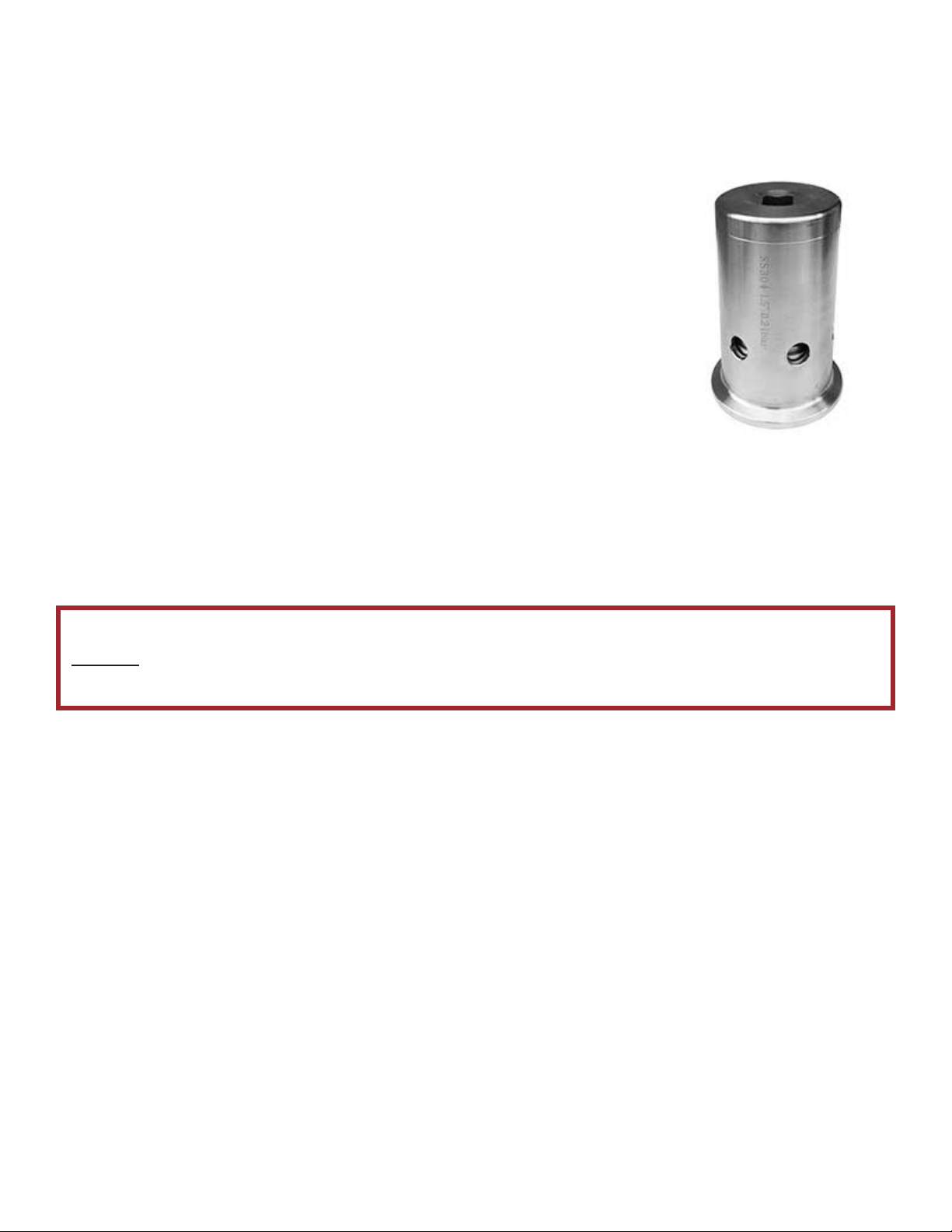
Use of a pressure and vacuum relief valve to prevent pressure build up
A vacuum breaker and pressure relief valve installed on a fermenter
lid port is a necessary accessory to help insure against damage to
a fermenter (and possible injury) caused by pressure or vacuum. A
vacuum, caused by a cooling of liquid or gas inside the fermenter
can pull the sides in, and pressure building up from expansion or
gas produced during fermentation can push the walls out. In either
situation, the fermenter can be damaged, possibly beyond repair.
The BREWHA Vacuum Breaker and Pressure Relief valve serves
to protect your investment by opening when either 25mmHg of
vacuum or 3psig of pressure occurs in the 3-in-1 fermenter (14.9psig
in the 4-in-1 fermenters).
When a vacuum builds up, it pulls down on the valve, opening the
valve and letting air into the fermenter. When pressure
builds up, the relief valve is pushed open, letting gas escape.
It is important to note that a safety relief valve should always
be used in ADDITION to a blow o hose or air lock, and never be used as the primary means
for release of gas; the reason, is that in the event where a fermenter was overlled (and/or
fermentation too vigorous) krausen (foam) could enter the opening mechanism and prevent the
valve from operating properly and this is more likely to occur if used for primary gas relief.
8
BIAC User Manual Safety
Warning: Never use the pressure relief valve as primary means of gas relief;
always use a large diameter blow-o hose for gas release and the relief valve as
a safety backup.
Figure 4

8
BIAC User Manual Safety
1
2
3
4
5
6
Preventing damage to vessel jackets
Every hose and tank is designed with a maximum allowable working pressure
(MAWP), which if exceeded, will cause damage and pose a safety hazard. The
BREWHA tank jackets have been designed to hold up to 5psi of pressure (7psi in
the Microbrewery 4-in-1 fermenters), which is more than enough to allow adequate
ow rates for chilling wort and maintaining temperature during fermentation.
In many regions, tap water is a cost-eective source of chillant. Ground, river or lake
water is often delivered at temperatures below what is necessary for pitching yeast,
so it provides a much less costly source of chilled water than an electric chiller is
able to provide. (Where tap water temperature is higher than what is necessary
for yeast, or to conserve water, a combination of using tap water—to perform the
lion’s share of the cooling —and then switching to electrically chilled water can be
a cost-eective way to chill.) Tap water, however, is often supplied at pressures
well above the design tolerance of the BREWHA vessels, so if it is fed directly
into the jacket of a vessel, it could cause pressure inside the jacket to quickly rise
above the maximum limit, damaging the vessel. To ensure that pressure doesn’t
rise above the allowable limit when using tap water (brewery pumps can provide
high-pressure water too, so caution is needed with them as well) NEVER throttle
or restrict the exit ow from the jacket in any way, and a water pressure regulator
should be installed on the feed line, prior to the vessel. The ¼” Watts 560 (which
supplies approx 10L(2.5gal)/min) or similar regulator can be used for maintaining
fermentation temperature or for chilling post-boil in the smaller tanks. For chilling
where a higher volume of chilling water is needed for more rapid chilling, such as
when chilling wort post boil in the 5 and 7BBL 4-in-1s, a ½” or ¾” regulator on the
brewery water lines could be sourced from a local plumber, and/or a small plate
chiller can be used in addition to the jacket to assist with chilling (a pump can be
used to circulate wort out of a side port, through the plate chiller, and back into the
fermenter; run boiling wort through
for a few minutes to sanitize the plate
chiller, pump and hoses, and clean
thoroughly immediately after use).
When installing any regulator, it is
almost always necessary to ensure
that the ow of water through the
regulator is in the same direction as
indicated by the arrow on the side.
9
Caution: When installing a Water Pressure Regulator, ensure that the
arrow on the regulator points in the direction of ow, or it will not
operate correctly and may cause damage or injury.
Figure 5
10
BIAC User Manual Installation
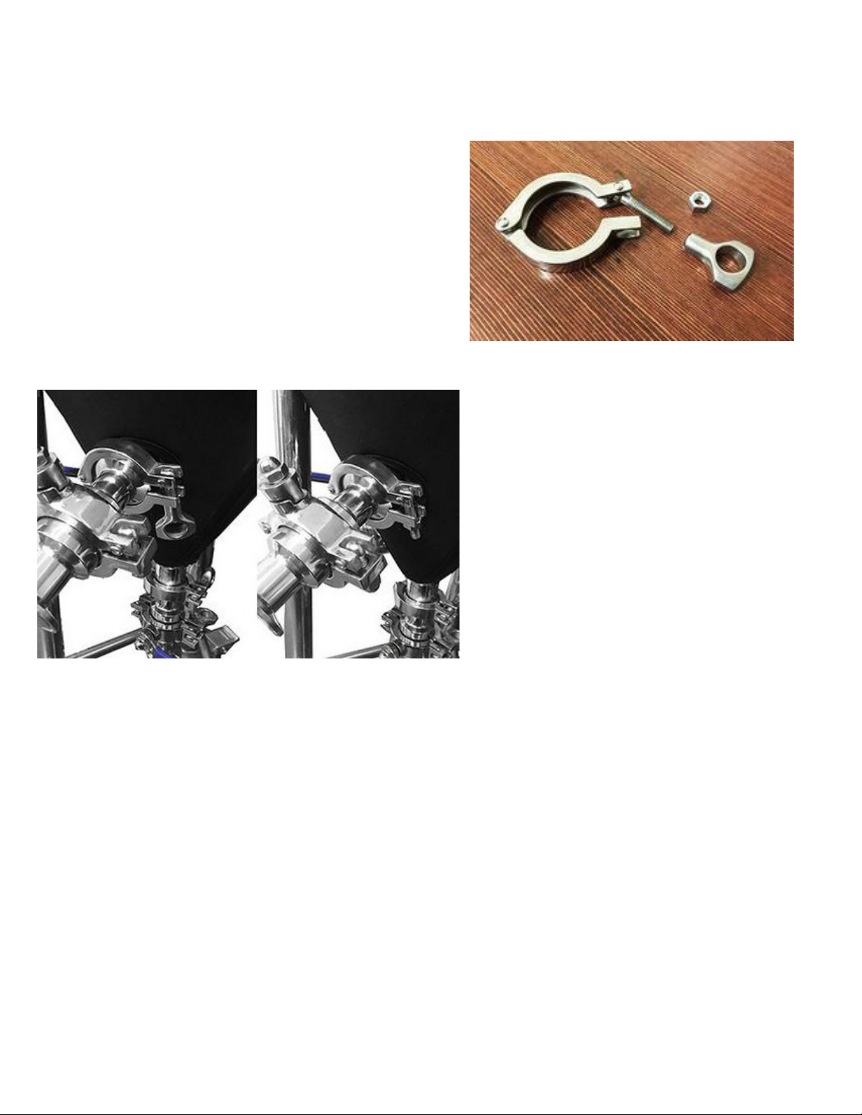
Securing sanitary clamps against accidental loosening
Caution needs to be taken when loosening the
sanitary clamps to ensure that the correct clamp
is being loosened. Otherwise, instead of removing
a hose tting, one might remove the entire valve
and suddenly have contents spilling out of the
fermenter. It is bad enough if this occurs at the end
of fermentation and some beer is wasted, but it can
be very dangerous if this occurs during the boil.
If one is concerned this may happen to them, the
simplest way to ensure an important clamp is not
removed is by replacing the wing nut
(which is easy to remove quickly by hand)
with a standard hex nut as shown in
Figure 7 (which requires a tool). Most nuts
on BREWHA clamps are 5/16” and can
be purchased from hardware stores, but
bring one with you to ensure it ts before
purchase. If all the clamps that should not
be loosened until brewing is completed
have a hex nut, and only the clamps
that can be safely loosened without
consequence have a wing nut, the risk
of loosening the wrong clamp is greatly
decreased.
Figure 6
Figure 7

10
BIAC User Manual Installation
1
2
3
4
5
6
Installation
Table of Contents
Cleaning and sanitizing stainless brewing equipment and preventing rust ...... 12
Assembling the BREWHA BIAC ...... 15
Assembling the BREWHA Sanitary Ball Valve ...... 24
Installing the BREWHA Water Heating Element ...... 25
Installing the BREWHA Brewing Power Controller ...... 27
Programming and Operating the BREWHA ETC ...... 32
Installation and Operation of the Water, Beer and Wort Chiller ...... 36
For additional information on installation and operation select the ‘Installation’ category at the top of
the ‘Learn’ page on the website:
https://brewhaequipment.com/blogs/howtobrewbeer/tagged/installation
For product manuals or for specic instructions for a particular accessory, refer to that product page
on the website, or select the ‘Instruction Manuals’ category at the top of the ‘Learn’ page on the web-
site: brewhaequipment.com
https://brewhaequipment.com/blogs/howtobrewbeer/tagged/instruction-manuals
For information on what other items are needed for your brewery, refer to this page:
https://brewhaequipment.com/pages/what-else-is-needed-for-my-brewery
11

12
BIAC User Manual Installation
Cleaning and sanitizing stainless brewing equipment and preventing rust
One of the very useful features of the BREWHA BIAC is that the fermenter is boiled in which
makes perfect sanitation much easier to achieve—the heat of the boil will sanitize the fermenter
so chemically sanitizing the vessel is not necessary. All that is needed is to clean the fermenter
out well with water and a soft cloth after the beer is removed, disassemble and clean out the
valves and ports, and clean the elements well and it is ready to go for the next batch.
However, when having just purchased a new BREWHA vessel (including the 3-in-1 and 4-in-1)
or if beer stone builds up after several brews, deeper cleaning might be necessary. With a new
vessel it is important to remember that the vessel comes direct to you from the shop where it
is hand-made. This means that there could be a small amount of oil or welding stains on the
vessel and there could be welding material or polish inside the jacket so a thorough cleaning of
your vessel and ushing out of your jacket should be completed before starting to brew. (It is
especially important to clean out your jacket well if you will be using it for providing sparge water
during mashing.)
For keeping your equipment clean we strongly recommend cleaning immediately after brewing
(or with the fermenter, as soon as you transfer beer out) as residue will be much easier to
remove before it dries. Use a soft cloth or stainless steel safe scrubber and don’t use steel wool
to scrub the vessel as this will scratch the mirror polish nish. A non-abrasive scrubber such as a
100% copper scrub brush can be helpful to clean scorched or caramelized sugar o the heating
element. Always clean the elements well after each brew to ensure they don’t scorch. It is
also recommended to disassemble the valves when cleaning and wipe out any visible sediment
(heat from the boil will take care of the rest), and take care not to stretch the silicone lid or valve
gaskets as they may deform.
The best sanitizer is heat. If chemical sanitation is necessary or
preferred, we recommend STAR SAN. Since the lid is generally o
during boil, it is benecial to put the lid on the fermenter for the
last few minutes of boil to let the steam heat it up (be careful to
allow steam to escape and that foaming up does not occur), and
to run a little boiling wort through the valves/racking arm and/or
to spray a little Star San on the lid and ports and hoses. Chemicals
only sanitize surfaces so it is important to have items clean.
It is important to note that ‘stainless’ steel is a bit misleading as it
doesn’t mean it will never stain or rust. It should actually be called
‘harder-to-stain’ steel. The following is an interesting excerpt by
General Electric on taking care of stainless steel.
The largest single component of stainless steel is steel.
Steel will rust. The chromium in stainless steel when exposed to oxygen in the atmosphere
forms a thin invisible layer called chromium oxide. This invisible layer covering the entire
surface gives stainless steel its ability to resist stains and rust. If this layer is damaged rust is
Figure 8

12
BIAC User Manual Installation
1
2
3
4
5
6
formed on the surface at the point of that damage. The good news is, with a little
cleaning and care the chromium oxide layer is self -healing...
Stainless steel and the chromium oxide layer actually thrive on proper cleaning.
For everyday cleaning of non oxidized soils, dust, dirt and ngerprints, a mild
soap/detergent (dish detergent) and warm water solution should be used. Use
the solution to remove the soil, rinsing with fresh water and a clean cloth, and dry
completely.
To clean spots (cosmetic) from the stainless
we recommend using Bar Keeper’s Friend, and
it also works well to remove rust spots and
to ‘heal’ areas that might be open to rust. A
periodic full vessel cleaning with an acid such
as citric acid or is in Bar Keeper’s Friend can
also help preserve the entire fermentor and is
recommended for getting greatest longevity
from your stainless steel.
While stainless is fairly durable, it needs to be
treated with care. Some chemical cleaners can
actually attack and degrade stainless steel. John
Palmer in his book How to Brew provides the
following summary:
For general cleaning, mild detergents or
percarbonate-based cleaners are best
for steel and aluminum. Bleach should be avoided because the high pH of a
bleach solution can cause corrosion of aluminum and to a lessor degree of
stainless steel...the corrosion inhibitor in stainless steel is the passive oxide layer
that protects the surface. The 300-series alloys (a.k.a. 18-8 alloys) commonly
used in the brewing industry are very corrosion-resistant to most chemicals.
Unfortunately, chlorine is one of the few chemicals to which these steels are not
resistant. The chlorine in bleach acts to destabilize the passive oxide layer on
steel, creating corrosion pits. This type of attack is accelerated by localization and
is generally known as crevice or pitting corrosion.
Many brewers have experienced pinholes in stainless-steel vessels that have
been lled with a bleach-water solution and left to soak for several days. On a
microscopic scale, a scratch or crevice from a gasket can present a localized area
where the surface oxide can be destabilized by the chlorine. The chlorides can
combine with the oxygen, both in the water and on the steel surface, to form
chlorite ions, depleting that local area of protection. If the water is not circulating,
the crevice becomes a tiny, highly active site relative to the more passive stainless
steel around it and corrodes. The same thing can happen at the liquid surface if
13
Figure 9

14
BIAC User Manual Installation
the pot is only half full of bleach solution. A dry stable area above, a less stable but very large
area below, and the crevice corrosion occurs at the waterline. Usually this type of corrosion will
manifest as pitting or pinholes because of the accelerating eect of localization.
A third way chlorides can corrode stainless steel is by concentration. This mode is very similar
to the crevice mode described above. By allowing chlorinated water to evaporate and dry on a
steel surface, those chlorides become concentrated and destabilize the surface oxides at that
site. The next time the surface is wetted, the oxides will quickly dissolve, creating a shallow pit.
When the pot is allowed to dry, that pit probably will be one
of the last sites to evaporate, causing chloride concentration
again. At some point in the cleaning life of the pot, that site will
become deep enough for crevice corrosion to take over and
the pit to corrode through.
It is best to not use bleach to clean stainless steel and other
metal. There are other cleaners available that work just as well
without danger of corrosion. The percarbonate-based cleaners
like PBW are the best choice for general cleaning.
If you have a particularly tough stain, liked burned malt extract,
then you may need something stronger. There are oxalic
acid based kitchen cleansers available at the grocery store
that are very eective for cleaning stains and deposits from
stainless. They also work well for copper. One example
is Revere Ware Copper and Stainless Cleanser, another is
Bar Keeper’s Friend, and another is Kleen King Stainless Steel Cleanser. Use according to the
manufacturer’s directions and rinse thoroughly with water afterwards.
To clean spots (cosmetic) from the stainless we recommend using Bar Keeper’s Friend, and
it also works well to remove rust spots and to ‘heal’ areas that might be open to rust. For
passivating a larger area, or in areas that are hard to reach (such as between wedge wire or in
jackets) circulating for 30-60 minutes with a 10% citric acid solution (other acids can be used but
citric acid is food safe and readily available) at 65C/150F and letting the area fully air dry for 12
hours before rinsing is generally all that is needed to mend any damaged areas to help preserve
the fermentor and get the greatest longevity from your stainless steel. Five Star’s Acid Cleaner #5
is also eective for passivating stainless as well as removing stubborn stains and deposits (it is
available at most brewing supply stores).
Additional instructions on care of stainless can be found at the following link to the Specialty
Steel Association of North America’s guide to ‘Care and Cleaning of Stainless Steel’.
A detailed discussion on care of stainless is the Nickel Development Institute’s ‘Cleaning and
Descaling of Stainless Steel’.
Figure 10
14
BIAC User Manual Installation
1
2
3
4
5
6
Assembling the BREWHA BIAC
Assembly of the BIAC is relatively intuitive and straightforward and can be
assembled and ready to brew in just a few hours. A brewer may want to substitute
or alter a few parts, which is entirely acceptable, but this description explains
how to assemble it in the typical manner. The BIAC being shown here is the Small
version; larger models are almost identical. The Microbrewery 4-in-1s (MB) are
almost identical to the Homebrewery 3-in-1s (HB) for almost all aspects of the
install (special note will be made where they dier).
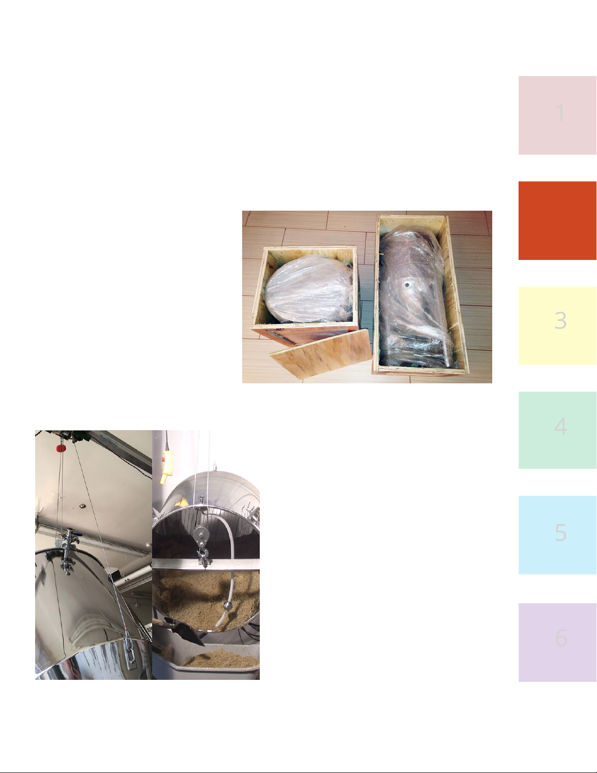
1. The BIAC will arrive in two
wooden crates. The fermenter (3-
in-1 fermenter with Homebrewery
systems and 4-in-1 fermenter with
Microbrewery systems) in one
crate and the Mash Colander in
the other. Remove the screws and
withdraw the vessels. The ttings
and accessories are packaged
inside bags inside the vessels or in
separate boxes. Before emptying
the ttings out of the bags, look at
the packing list inside the bag as
it may help you identify where the
ttings from that bag should be installed.
2. The lift beam (or cable) included with
the complete accessories package can
be used to help remove the vessels from
the crates (the larger vessels have lift
lugs for this purpose). Ensure your hoist
or lifting mechanism is securely installed
according to manfuacturers instructions
and at no time operate underneath the
vessel in a way that could cause bodily
harm if the hoist fails. The Colander
Tipping Cable (with 1.5-7BBL) that will be
used to dump the mash can be installed.
It comes with the upper end already
nished (connect to hoist trolley) with
an hourglass sleeve and thimble and
extra cable on the lower end. For the
lower end, adjust the cable to the length
you need so that when the Colander is
tipped, the bottom will be above your
15
Figure 11
Figure 12
16
BIAC User Manual Installation
grain disposal receptacle so the spent grain can be
easily unloaded. Then cut the cable and securely
fasten the hourglass sleeve with a swaging tool once
the thimble is in place.
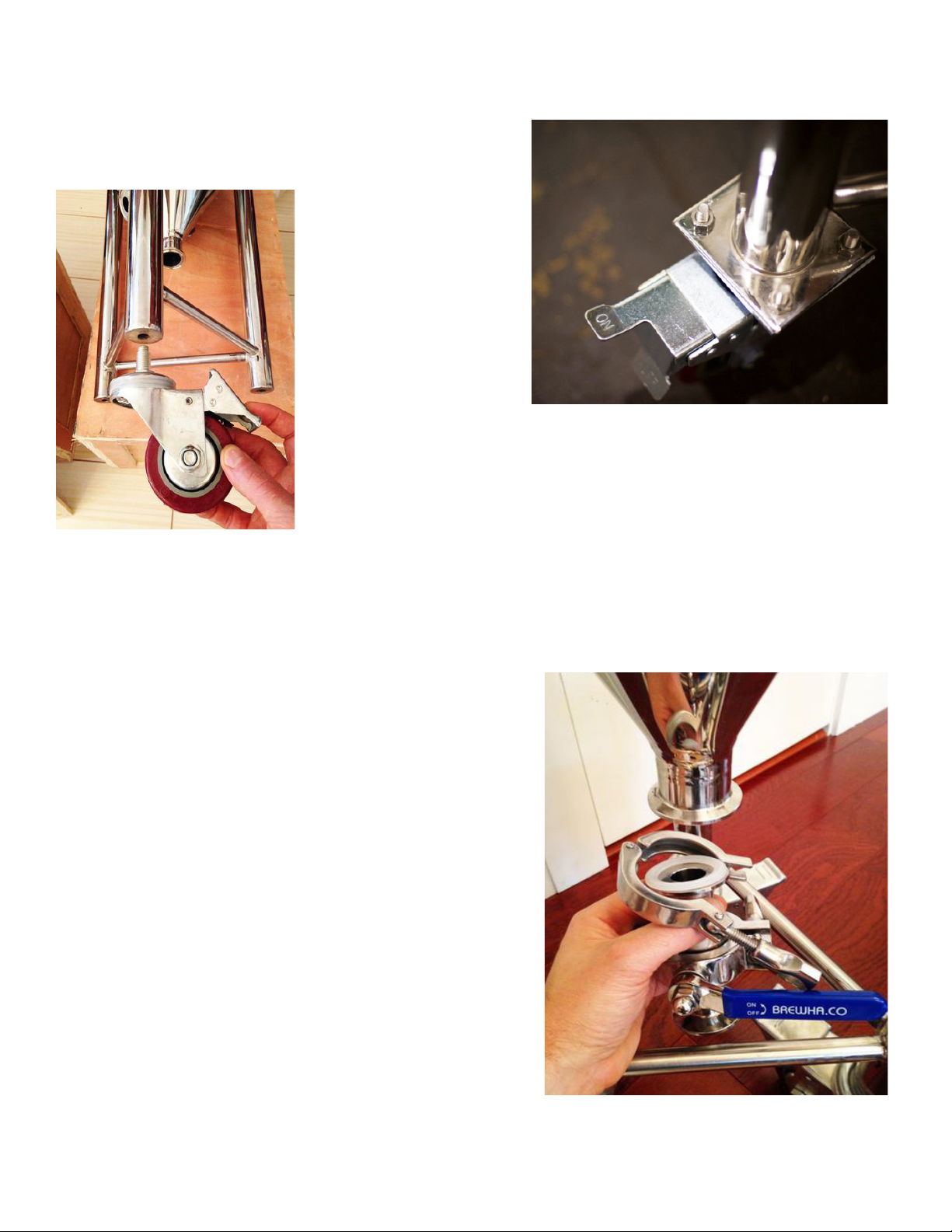
3. The fermenter is
shipped without the
casters installed to
prevent damage in
transit. To install the
casters for the smaller
fermenters, rst lock
the wheel which will
allow the caster/
bolt to be turned in
manually (Figure 13). The
casters on the larger models attach with four M8 bolts and there
are two swivel casters and two xed casters for each fermenter.
The xed casters should be installed on the side opposite of the
fermenter push bar. The bolts should be installed through the
caster plate and fermenter leg plate with the nut side up, so the bolt
does not impede movement of the swivel caster (Figure 14). Only use the fermenters on a at,
smooth surface and use wheel chocks to prevent rolling. To minimize risk of accidental tipping,
fermenters should not be moved when full, or if moved, moved with extreme care.
3. Attach the rst of the four sanitary valves (ve with
the 1.5BBL, 3BBL, 5BBL and 7BBL) to the bottom port
of the fermenter by placing a gasket between the
vessel and the valve and attaching a clamp; use the
large valve (1-3/8” dump valve) here if you purchased
one with the smaller tanks, or the 2” buttery valve
with the larger tanks. The valve can be installed in
either direction and it will not aect performance.
(With the large dump valve and the Small fermenter,
the handle may need to turn up to fully open the valve.
And during fermentation if using the Yeast Harvester
with the Small BIAC, use only the standard 7/8” valve.)
Tighten the valve clamp manually until it is snug.
Over-tightening (e.g. with a tool) could damage the
silicone gasket. (It is good to ll the fermenter with
water to check for leaks before each brew day. If a
valve is leaking, wiggling the handle while tightening
may help, or the valve may need to be reassembled
to ensure the gaskets are properly seated.) One can
attach a hose barb to the outer side of the valves to
Figure 13
Figure 14
Figure 15

16
BIAC User Manual Installation
1
2
3
4
5
6
17
connect your own hose (generally a large
hose barb will go on the bottom port to
assist in draining of trub/yeast cake from the
fermenter). During fermentation, the brewer
can dump yeast/trub out the bottom port
when fermentation is ending (after about
4-5 days with ales) to prevent the yeast ‘cake’
from getting too hard (be sure to rinse the
port thoroughly with water and sanitizer
after every use so that microbial growth
doesn’t occur).
4. There are two sizes (1.5” and 2” or 3”) of
Tri-clamp (TC) ferrules/ports on the cone
portion of the fermenter. The 2” TC ports (3”
on 7BBL only) are for heating elements—one
each on the fermenters up to 90L/24gal,
two on the 1.5BBL, four on the 3BBL, six on
the 5BBL and ve (3 phase) on 7BBL (see the
section later in the manual for instructions on
installing the heating elements). The uppermost 1.5” port on the side of the cone
is for the temperature sensor. The middle 1.5” port on the side of the cone is for
a racking valve (since it sits above the level that trub/yeast normally settles during
fermentation it can be used to transfer/rack beer to kegs—other ports can be used
Figure 16
Figure 17 Figure 18
18
BIAC User Manual Installation
as well for racking if desired). A racking arm can be inserted here before the racking valve; when
using such a tting, a teon gasket will rotate more easily than silicone but is harder to seal. The
lower 1.5” port on the cone that only opens into the jacket (it doesn’t open into the fermenter) is
for chilling water to enter the jacket (see Step 5). The bottom dump port on the tip of the cone
was described in step 3 above. The Microbrewery 3–7BBL models have a fourth 1.5” port on the
cone, just above the bottom of the cone to which a valve
can be attached for connecting a serving or racking hose
(once yeast is removed), as well as a port on the lower
side of the cylindrical portion of the vessel to which a
valve or sight glass can be attached.
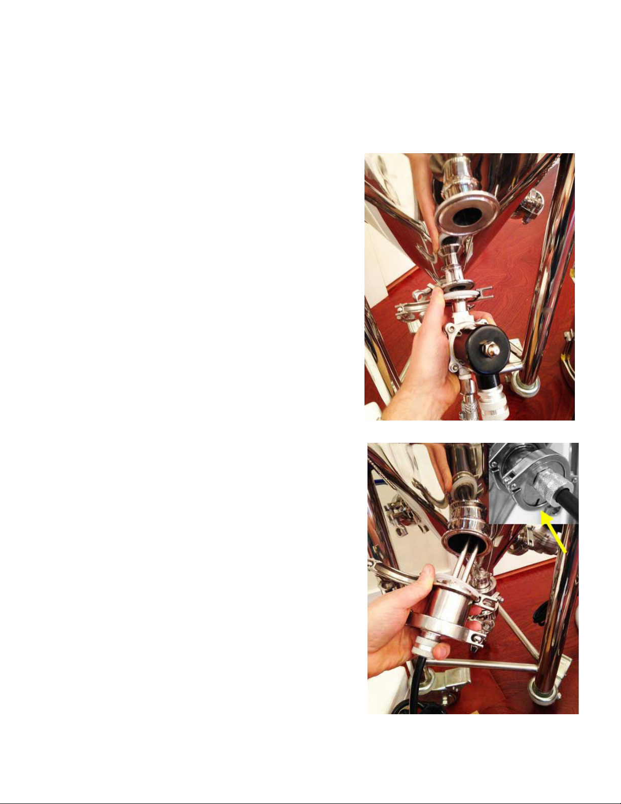
5. If using tap water for temperature regulation, attach
the Temperature Control Valve (TCV) to the 1.5” port
on the side of the cone that opens only into the jacket
of the fermenter, or, it might be easier to rst attach a
valve to the jacket port and then the TCV, since the TCV
can then be removed without emptying the jacket. This
might be the case when switching from tap water (after
cooling the boil) to Chiller water (during fermentation).
(Use only clean water with the TCV at temperatures
between 2°C/36°F and 40°C/104°F.) The TCV is used
to shut o chilling tap water going into the jacket to
cool the wort after boiling, and during fermentation
so doesn’t need to be installed until after the boil is
completed (especially with the 120V Small BIAC it is
best to leave the jacket empty during boil to reduce
heat loss). The power cord on the TCV should be
plugged into the ‘C’ or ‘blue snowake’ receptacle on the
Electronic Temperature (ETC) Controller (see section on
‘Programming and Operating the BREWHA ETC’ for more
information) or the Chiller cord on the Touchscreen
Controllers. If using warm water (don’t exceed
40ºC/104ºF) to warm the fermenter, connect the TCV to
the ‘H’ or ‘red ame’ receptacle on the ETC. The Water
Pressure Regulator (WPR) should be installed either
before or after the TCV (depending on whether you have
a WPR with garden hose or tri-clamp connectors) to
ensure that water pressure does not exceed the design
limit of the jacket. The regulator should be installed with
the arrow (etched on the back) pointing in the direction
of water ow. During fermentation, if using the Chiller
to maintain fermentation temperature, the TCV should
be removed and the Chiller pump (or the main Chiller
power) plugged into the ETC instead of the TCV and the
Chiller pump hose connected to the jacket inlet, and
Figure 19
Figure 20
18
BIAC User Manual Installation
1
2
3
4
5
6
19
the jacket exit hose returning to the Chiller
water reservoir (it should be submerged
and secured so it doesn’t move). When
the fermenter needs chilling, the ETC
will power the Chiller pump (or Chiller
itself) instead of the TCV to let cool water
circulate through the jacket. (See Chiller
installation section in this manual for more
details.)
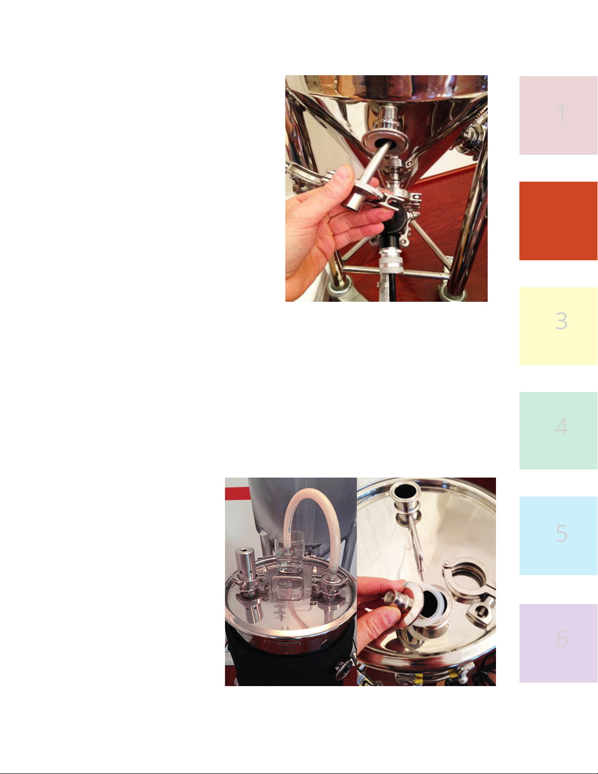
6. Attach the temperature sensor (liquid-
tight sensor or thermowell) through the
upper 1.5” port in the side of the cone.
7. Install the heating element and gasket
on the larger 2” port(s) on the side of the
cone (3” for the 7BBL). Install the element
with the slot on the outer cap of the guard
facing down (so it will drain if there is an internal leak).
8. Attach one of the 1/2” hose barbs to the upper jacket port. If you are using
tap water for chilling, connect a hose to this port and run to a drain. It is strongly
recommended to never close or impede ow out of the fermenter jacket in any
way, and to have a high quality, high-temperature kink-resistant hose attached
to the jacket exit port, so that back-pressure does not build up in the jacket and
damage the vessel. For closed-loop chillant circulation (e.g. with a BREWHA Chiller
during fermentation) connect your Chiller return hose to the jacket exit port and
run it back into the Chiller water reservoir (if the Chiller is below the top of the
jacket, the return hose should
be fully immersed and secured
in the water bath or air will enter
the jacket through the hose and
the jacket will empty, possibly
ooding the Chiller and your
oor). All ow out of the jacket
port should be unimpeded (e.g.,
no valve) in order to prevent
any pressure buildup; the jacket
is designed to withstand not
more than 5psi pressure (7psi
in the 4-in-1). A Water Pressure
Regulator can also be purchased
that will add a measure of safety
and should be installed on the
water line going into the jacket.
Figure 21
Figure 22
Table of contents
Popular Brewing System manuals by other brands

Bloomfield
Bloomfield 8740 owner's manual

BREWISTA
BREWISTA NutraMilk Quick start guides

Grindmaster
Grindmaster AMERICAN METAL WARE 87710 Installation and operation manual

Grindmaster
Grindmaster AT-2W Brochure & specs

Keg King
Keg King KegMaster Solstice installation guide

Grainfather
Grainfather S40 instructions


