BREWISTA Cold Pro Nitro User manual

Customer Service (North America): 1-888-538-8683
Local (Wyoming, USA): 307-222-6086
Email: help@mybrewista.com
READ THIS MANUAL PRIOR TO FIRST USE
AND SAVE FOR FUTURE REFERENCE
1-year Limited Warranty

2
IMPORTANT SAFEGUARDS
When using electrical appliances, basic safety precauons should always be followed
including the following:
• READ ALL INSTRUCTIONS.
• Place the unit vercally in a level, dry, and clean place.
• Operate dispenser within a temperature range of 42° - 95° F (6 - 35° C).
• To protect against risk of electrical shock, do not put body of the Cold Pro Nitro™
Machine in water or other liquid.
• Close supervision is necessary when any appliance is used by or near children.
• Always unplug from outlet when not in use, before pung on or removing parts
and before cleaning. To unplug, grasp plug and pull from electrical outlet. Never
pull cord.
• Avoid contacng moving parts. Do not insert objects into rotang parts (fan or
compressor).
• Prevent dirt (dust, bers, etc.) from entering the unit.
• Connect only the specied supply voltage.
• Protect the device against moisture, especially by penetrang liquids
• Do not operate any appliance with a damaged cord or plug, or aer appliance
has been dropped or damaged in any manner. Return appliance to the nearest
authorized service facility for examinaon, repair or adjustment.
• The use of aachments is not recommended as this may cause re, electric
shock or injury.
• The device is only approved for use with cold liquids and is not suitable for
cooling hot liquids, unltered liquids, chemicals or similar.
• Do not use outdoors.
• Do not let cord hang over edge of table or counter, or touch hot surfaces.
• Do not aempt to defeat the cover interlock mechanism.
• Be certain all removable doors and compartments are securely locked in place
before operang appliance.
SAVE THESE INSTRUCTIONS
3
ADDITIONAL SAFEGUARDS
DO NOT OPERATE APPLIANCE IF THE LINE CORD SHOWS ANY DAMAGE OR IF
APPLIANCE WORKS INTERMITTENTLY OR STOPS WORKING ENTIRELY.
EXTENSION CORDS
A short power-supply cord is to be provided to reduce the risk resulng from
becoming entangled in or tripping over a longer cord. Longer detachable power-
supply cords or extension cords are available and may be used if care is exercised in
their use. If a longer detachable power-supply cord or extension cord is used,
1) The marked electrical rang of the cord set or extension cord should be at least
as great as the electrical rang of the appliance, and
2) The extension cord should be a grounding-type 3-wire cord, and
3) The longer cord should be arranged so that it will not drape over the countertop
or tabletop where it can be tripped over, snagged, or pulled on unintenonally
(especially by children).
GROUNDING INSTRUCTIONS
This appliance must be grounded while in use.
CAUTION: To ensure connued protecon against risk of electric shock, connect to
properly grounded outlets only.
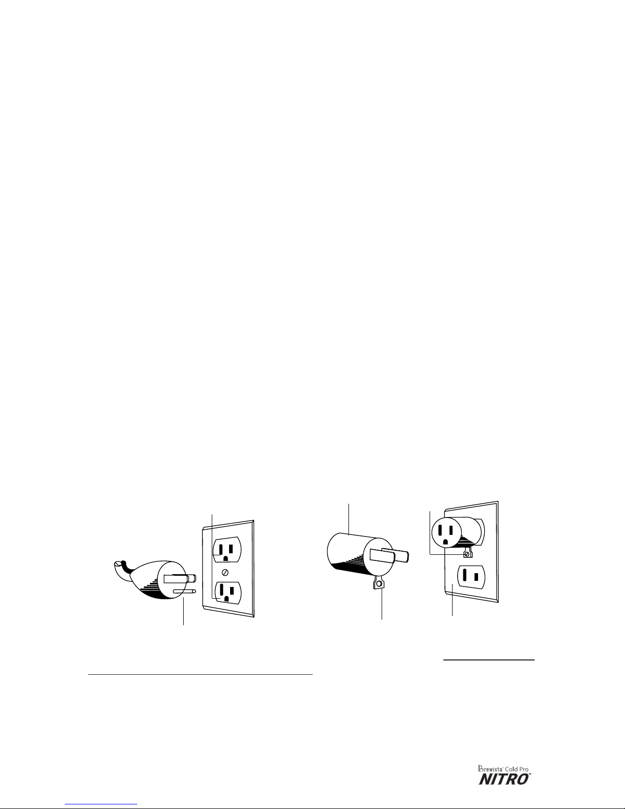
GROUNDING INSTRUCTIONS
In North American markets the appliance has a plug that looks like Figure A. DO NOT
aempt to insert a power cord into an incompable outlet. Appliance damage,
electrical system damage or physical harm may result. An adaptor, as shown in
Figure B, should be used for connecng a 3-prong grounding plug to a 2-wire
receptacle. The grounding tab, which extends from the adaptor, must be connected
to a permanent ground such as a properly grounded receptacle as shown in Figure
C, using a metal screw.
Warning: It is best to use this appliance on a dedicated circuit or with all other
appliances o during this appliance’s use. It will not damage electrical systems but
cauon should be used to not overload this circuit with other appliances running at
the same me.
Circuit grounding conductor
connected properly
Grounding prong
(A) (B)
Adapter
Grounding means
Adaptor
Cover of grounded
outlet box
Metal mounting
screw
(C)

4
Table of Contents
Cover/Customer Service Informaon 1
IMPORTANT SAFEGUARDS 2
ADDITIONAL SAFEGUARDS 3
Cold Pro Nitro™ Components 5
Intended Usage 6
Operaon Instrucons 6
• Assemble your Cold Pro Nitro™ 6
• Connect the Intake Line 6
• Connect your Cold Brew Container 7
• Dispensing your Nitro Cold Brew 7
• Adjustable Sengs 7
◦ Temperature 7
◦ Gas Level 7
◦ Flowrate 8
Higher Cooling Power for High Volume Dispensing 8
Filtraon 8
Decomissioning 8
Product Shelf Life 9
Downmes 9
Cleaning Instrucons 9
Maintenance 9
• Changing the Air Filter 10
• Remove Dust at Condensator Grid 10
• Changing O-rings and Connectors 10
Troubleshoong 11
1-year Limited Warranty Informaon 14
Correct Disposal of this Product 14
Warnings and Technical Data 15
5
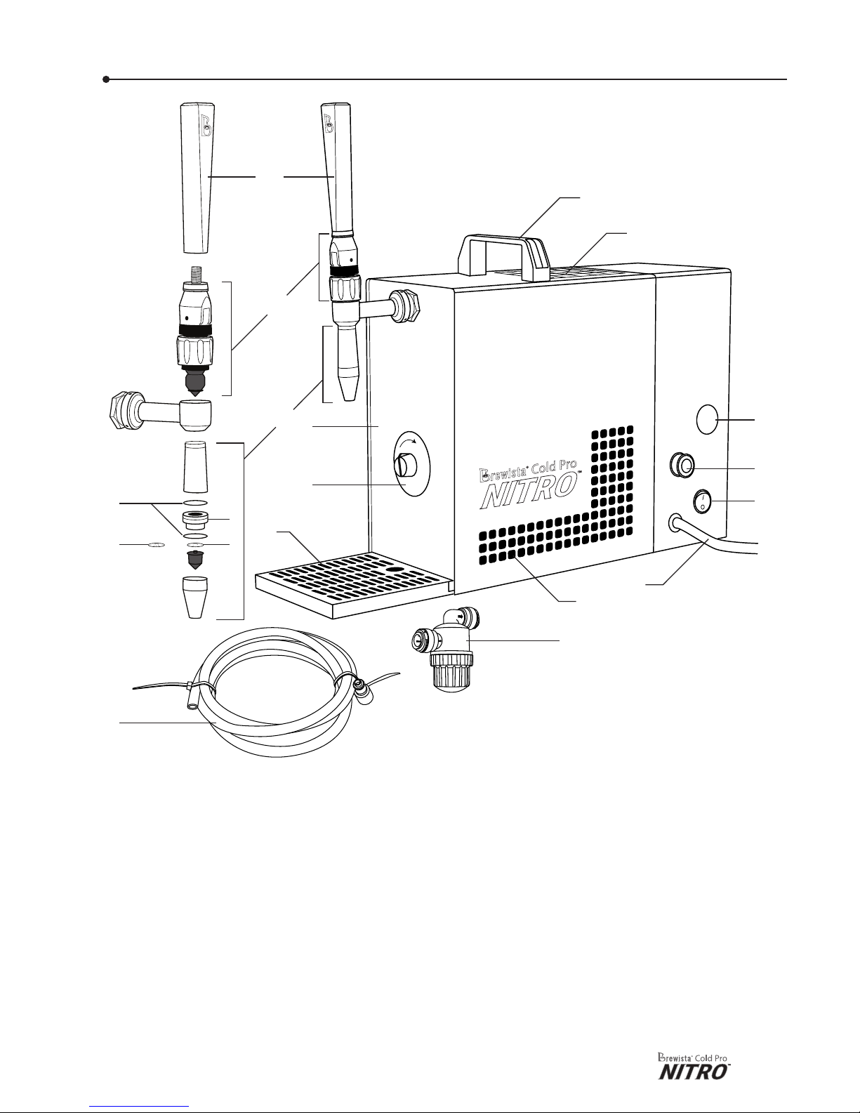
Cold Pro Nitro™ Components
1. Tap handle
2. Tap valve body
3. Jet-nozzle tap-outlet spout
4. Machine casing
5. Temperature control
6. Drip tray
7. O-rings
8. Strainer
9. 5 hole disc for fast tapping at
1.2 L / min
10. 2-hole disc for standard
tapping at 0.6 L / min
11. Intake line (2.0 m) with coupler to
connect to dispenser
12. Carry handle
13. Air intake vent
14. Gas control cap
15. Product intake port
16. Air compressor power switch
17. Power cord
18. Air output vent
19. Intake lter
6
5
4
19
18
17
16
15
14
13
12
1
3
2
9
11
7
10
8
Table of contents
Other BREWISTA Coffee Maker manuals

Popular Coffee Maker manuals by other brands


Bunn
Bunn LCA-1 Installation & operating guide

Chris Coffee Service
Chris Coffee Service Silvano owner's manual

Black & Decker
Black & Decker BLACK DECKER HOME DE790 Use and care book

Saeco
Saeco Vienna Plus Sup 018M operating instructions

INCAPTO
INCAPTO BXCO1470E Instructions for use

Bosch
Bosch TASSIMO finesse TAS16B Series user manual