1312
Professional Double Oven
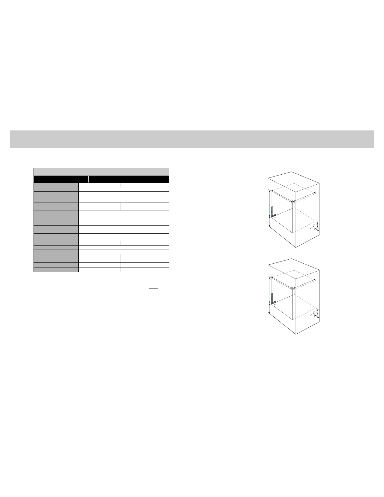
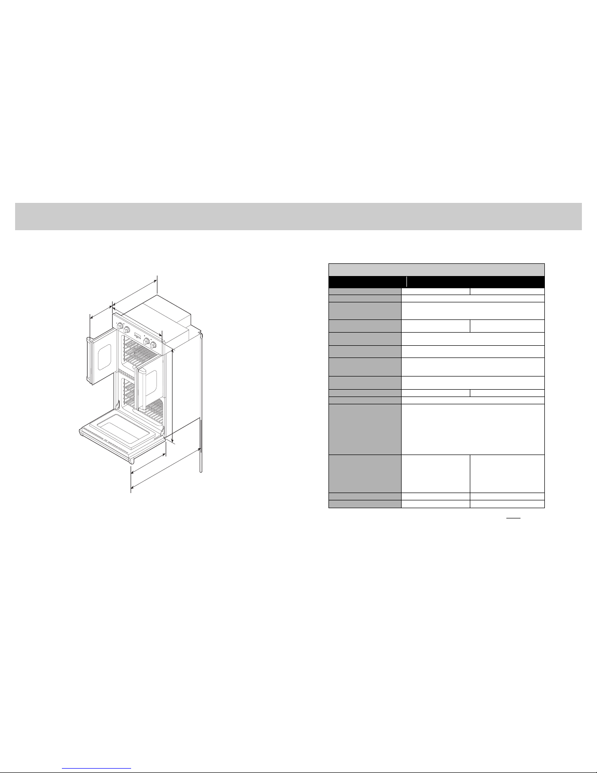
Description
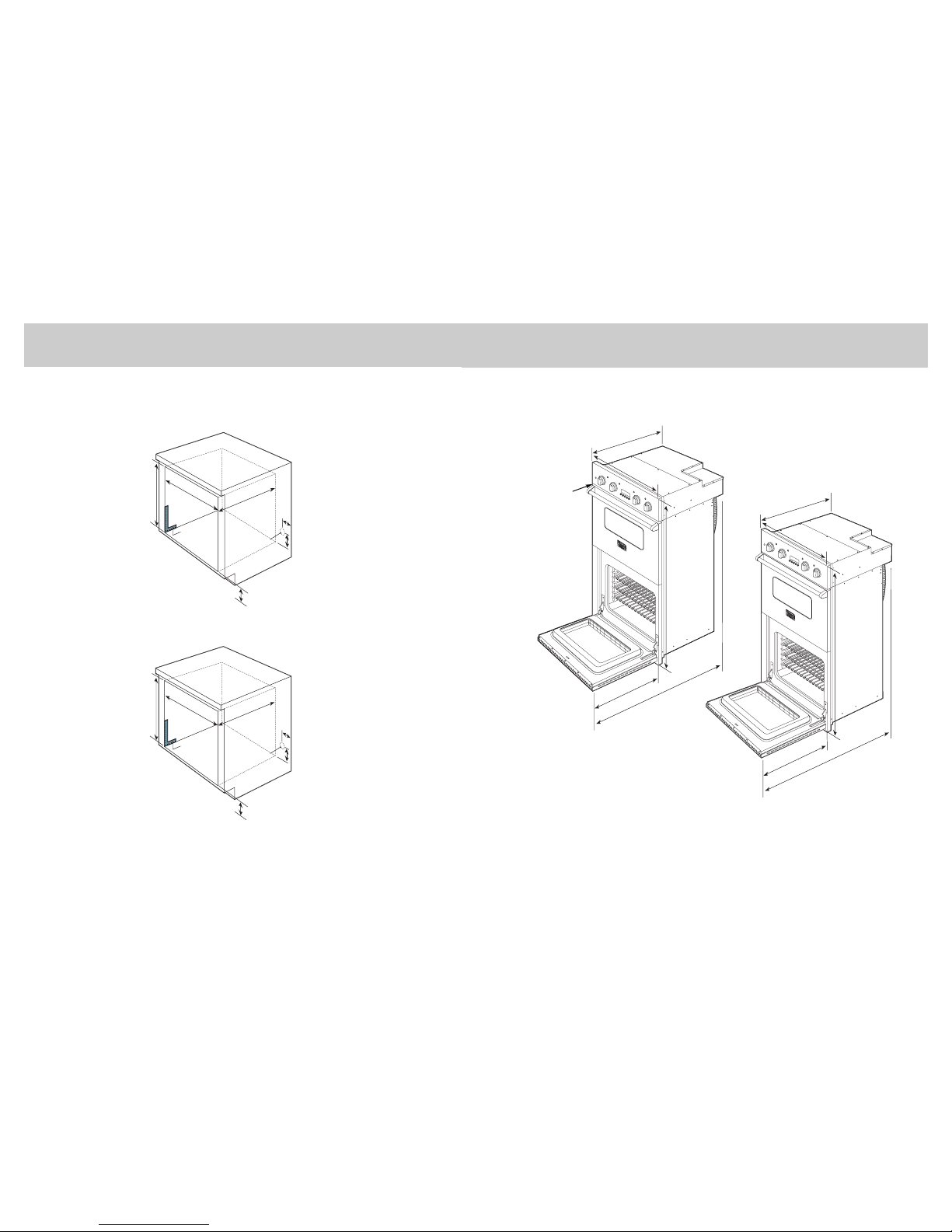
- 27” Wide - 30” Wide
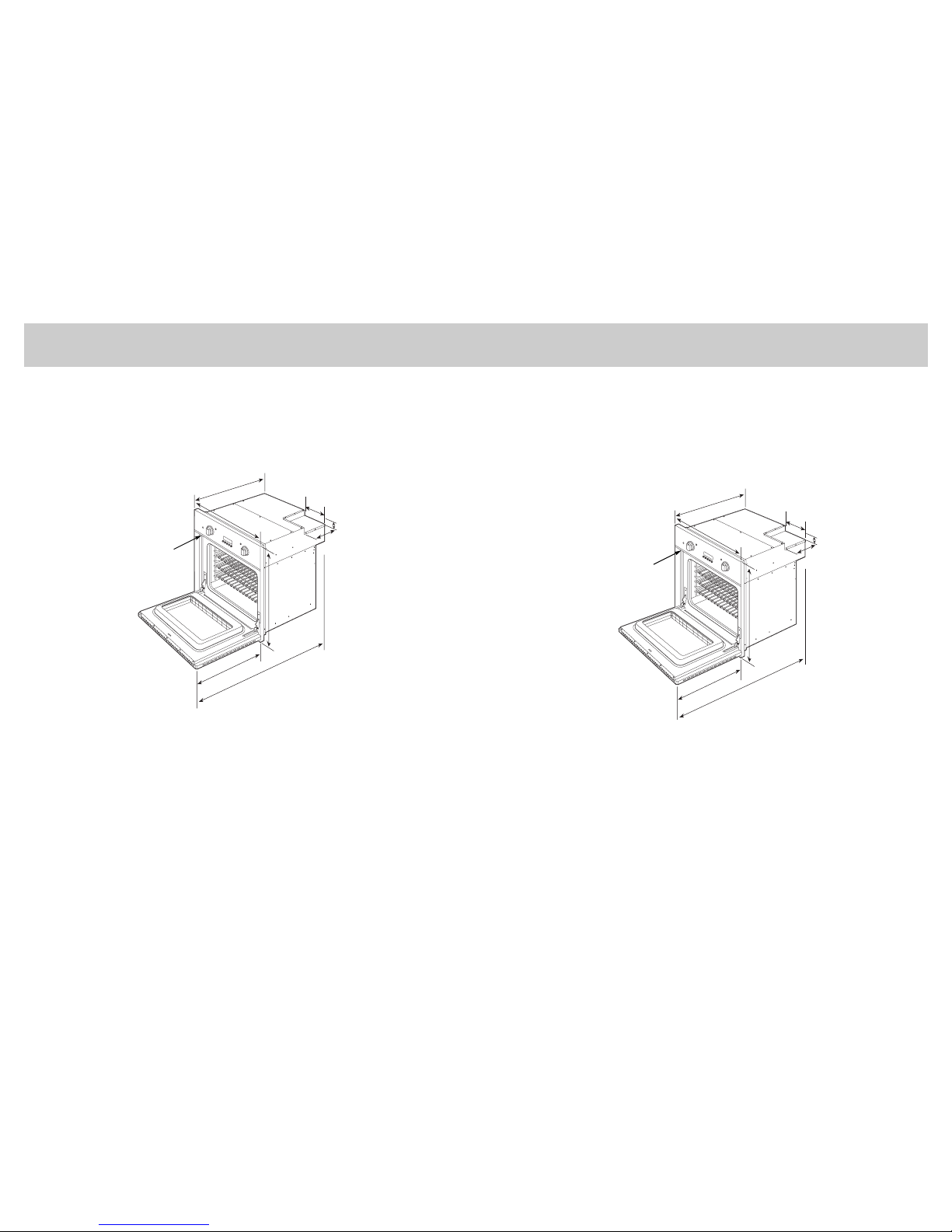
Overall Width 26-1/2” (67.3 cm) 29-1/2” (74.9 cm)
Overall Height 51-7/8” (131.7 cm)
Overall Depth to edge of control panel—25-3/4” (65.4 cm)
with door open (Select/Premiere Models)—46” (116.8 cm)
with door open (French Door Models)—39-1/2” (100.3 cm)
Cutout Width Standard—25-1/2” (64.8 cm)
Flush Mount—26-15/16” (68.4 cm)*
Standard—28-1/2” (72.4 cm)
Flush Mount—29-15/16” (76.0 cm)*
Cutout Height Standard—50-5/8” (128.6 cm)
Flush Mount—53-1/4” (135.3 cm)*
Cutout Depth Standard—24” (60.9 cm)
Flush Mount—25-3/4” (65.4 cm)*
Electrical Requirements 4-wire ground, 240VAC, 50 amp electrical connection
Unit is equipped with No.10 ground wire in conduit.
Should be fused separately.
Maximum Amp Usage 40.0 amps—240 VAC
34.7 amps—208 VAC
Oven Interior Width–both ovens 22-5/16” (56.7 cm) 25-5/16” (64.3 cm)
Oven Interior Height–both ovens 16-1/2” (41.9 cm)
Oven Interior Depth Upper Oven:
16-13/16” (42.7 cm) - AHAM
19-1/2” (49.5 cm) - Overall
Lower Oven - VEDO1272/VEDO1302/VEDO1302(T):
18-1/2” (46.9 cm) - AHAM
19-1/2” (49.5 cm) - Overall
Lower Oven - VEDO5272/VEDO5302/VEDO5302T/VDOF730 :
16-13/16” (42.7 cm) - AHAM
19-1/2” (49.5 cm) - Overall
Oven Volume
(measured to AHAM standard)**
Upper Oven: 3.6 cu. ft.
Lower Oven:
CVEDO1272: 4.0 cu. ft.
CVEDO5272: 3.6 cu. ft.
Upper Oven:
CVEDO1302(T)/CVEDO5302(T): 4.1 cu. ft.
CVDOF730: 4.3 cu. ft.
Lower Oven:
CVEDO1302(T): 4.5 cu. ft
CVEDO5302(T): 4.1 cu. ft.
CVDOF730: 4.1 cu. ft.
Oven Volume (Overall) Both Ovens: 4.1 cu. ft. Both Ovens: 4.7 cu. ft.
Approximate Shipping Weight 360 lbs. (163 kg) 402 lbs. (182 kg)
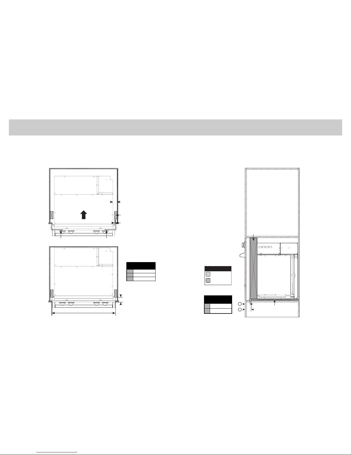
*Flush mount dimensions are for Select and Premiere models only. French door models cannot be
installed flush to cabinets.
**The AHAM Standard for measuring oven capacity subtracts the door plug and convection baffle
dimension from the total oven volume.
Specifications & Electrical RequirementsDouble Oven Dimensions (French Door Models)
(For cutout dimensions - refer to pages 14 and 15)