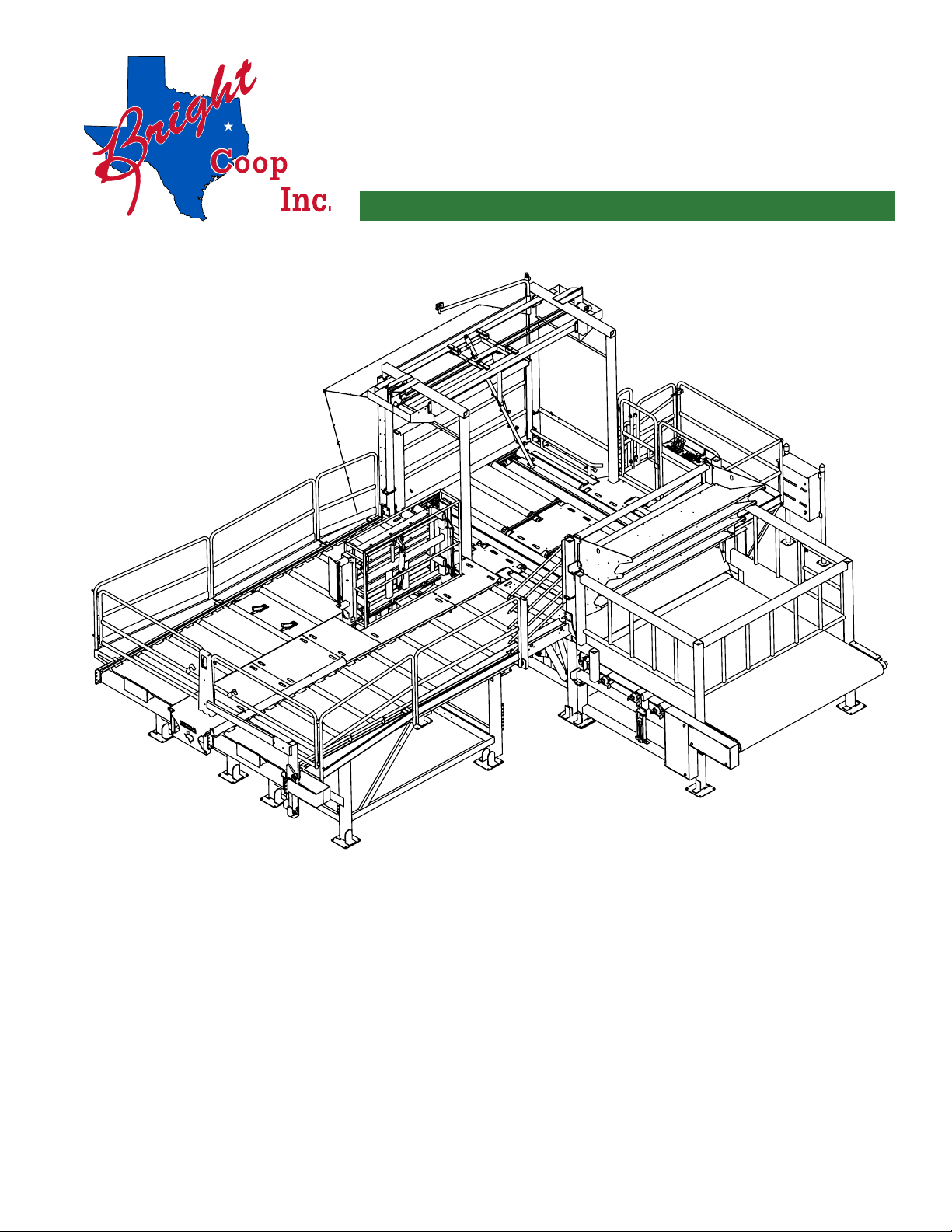
Operator's & Maintenance Manual
Cage Unloading System
3
CONFIGURATION............................................................................................................................................................................ 4
QUICK REFERENCE ........................................................................................................................................................................ 5
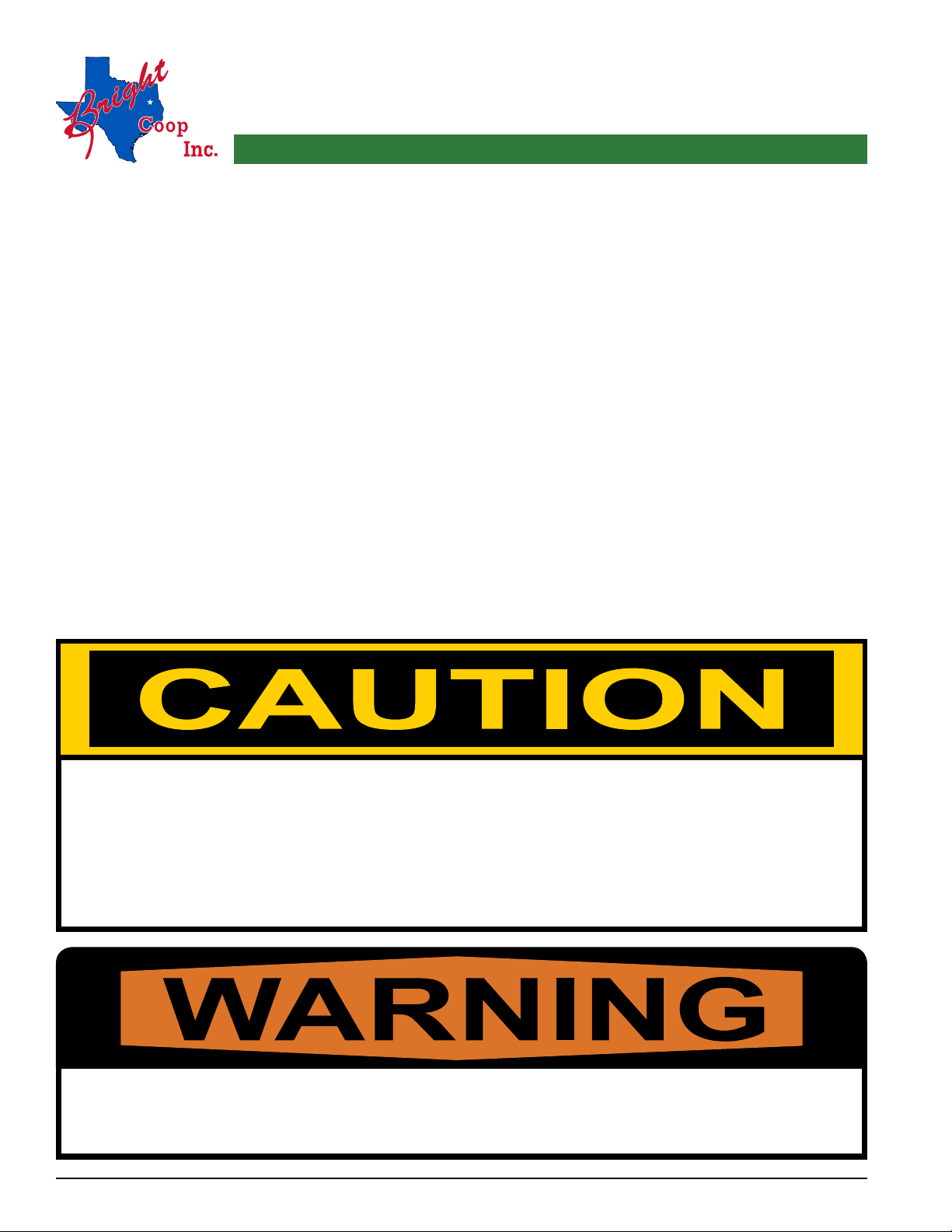
IMPORTANT! PRECAUTIONS & DANGERS ............................................................................................................................... 7
FOR THE OPERATOR ............................................................................................................................................................ 7
FOR MAINTENANCE PERSONNEL ..................................................................................................................................... 8
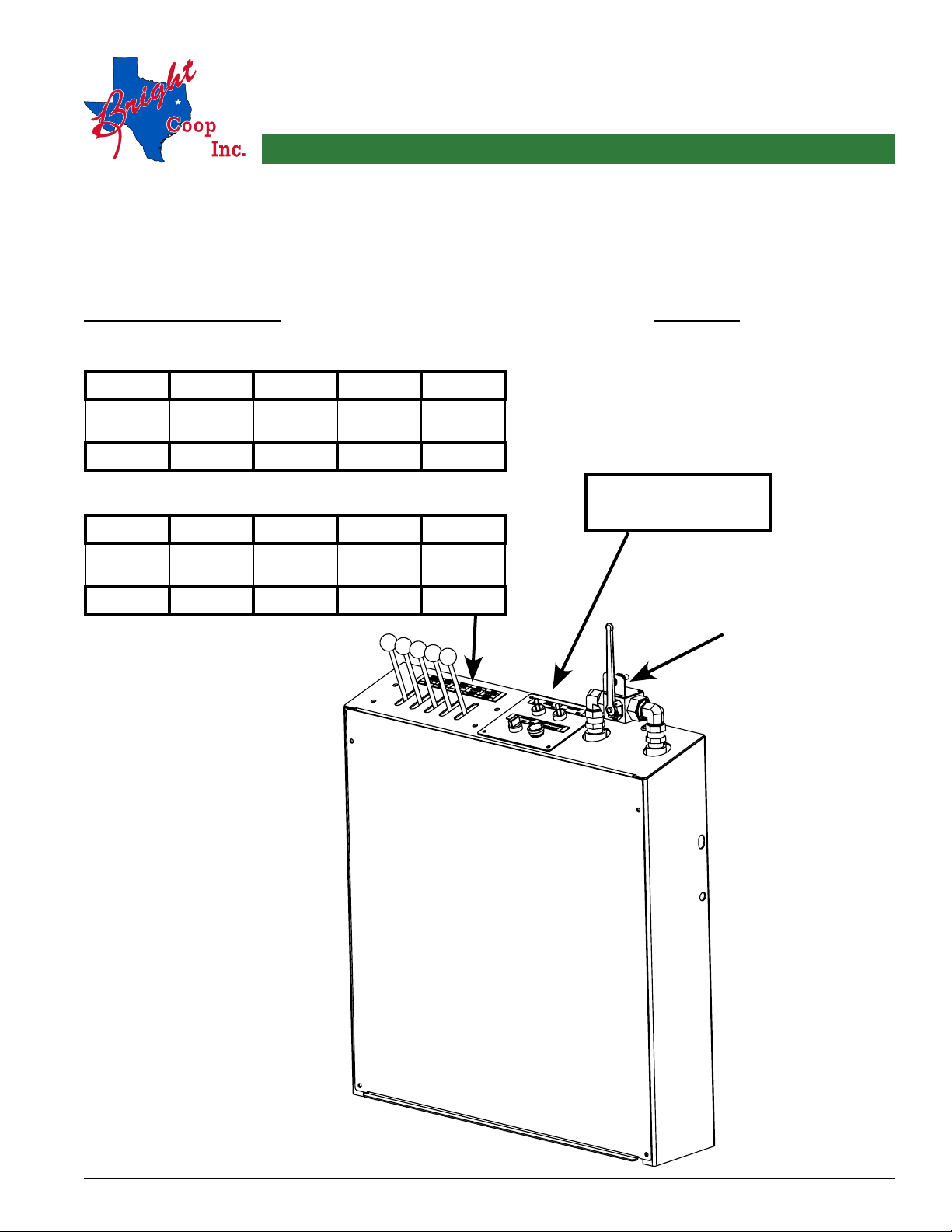
OPERATOR CONSOLE FUNCTIONS & CONTROLS................................................................................................................... 9
LEVER FUNCTIONS.............................................................................................................................................................. 11
UNLOADING SYSTEM WITHOUT CAGE WASHING SYSTEM...................................................................................... 15
UNLOADING SYSTEM WITH CAGE WASHING SYSTEM ............................................................................................. 17
OPERATING PROCEDURES......................................................................................................................................................... 20
VISUAL INSPECTION PRIOR TO OPERATION............................................................................................................... 20
UNLOADING SYSTEM WITHOUT CAGE WASHING SYSTEM...................................................................................... 21
UNLOADING SYSTEM WITH CAGE WASHING SYSTEM ............................................................................................. 30
MAINTENANCE.............................................................................................................................................................................. 40
MAINTENANCE, UNLOADING SYSTEM........................................................................................................................... 40
MAINTENANCE SCHEDULE QUICK REFERENCE.......................................................................................................... 47
RECOMMENDED HYDRAULIC FLUID .............................................................................................................................. 48
WARRANTY AND LIMITATIONS OF LIABILITY..................................................................................................................... 49
DUMPER TROUBLESHOOTING ................................................................................................................................................... 51
SCHEMATICS.................................................................................................................................................................................. 60
ELECTRICAL SCHEMATIC (TRANSFER CHAIN) (091-21963-01).................................................................................. 61
ELECTRICAL SCHEMATIC (TRANSFER CHAIN) (091-21963-02).................................................................................. 63
ELECTRICAL SCHEMATIC (TRANSFER CHAIN AND WASHER) (091-21964-01)...................................................... 65
ELECTRICAL SCHEMATIC (TRANSFER CHAIN AND WASHER) (091-21964-02)...................................................... 67
ELECTRICAL SCHEMATIC HYDRAULIC POWER UNIT (091-22900)........................................................................... 69
ELECTRICAL SCHEMATIC SMART RELAY (091-21961T) ............................................................................................. 71
ELECTRICAL SCHEMATIC SMART RELAY (091-21961W) ............................................................................................ 73
HYDRAULIC SCHEMATIC CAGE UNLOADING SYSTEM WITHOUT WASHER (091-23900) ................................... 75
Table of Contents