GSi 21' Diameter Gamma User manual

PNEG-2145
21' Diameter Gamma
Roof Assembly Instructions
Construction Manual
PNEG-2145
Version: 1.0
Date: 03-31-17

2 PNEG-2145 21' Diameter Gamma Roof Assembly Instructions
All information, illustrations, photos, and specifications in this manual are based on the latest
information available at the time of publication. The right is reserved to make changes at any
time without notice.

Table of Contents
PNEG-2145 21' Diameter Gamma Roof Assembly Instructions 3
Contents
Chapter 1 Safety ..................................................................................................................................... 4
Safety Guidelines .................................................................................................................................. 4
Cautionary Symbols Definitions ............................................................................................................ 5
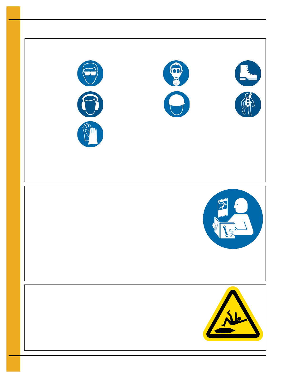
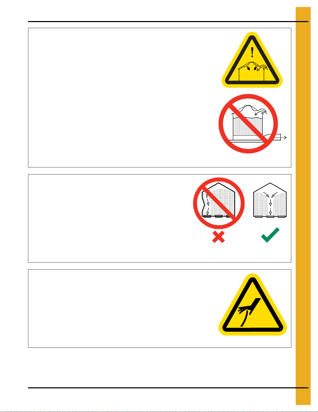
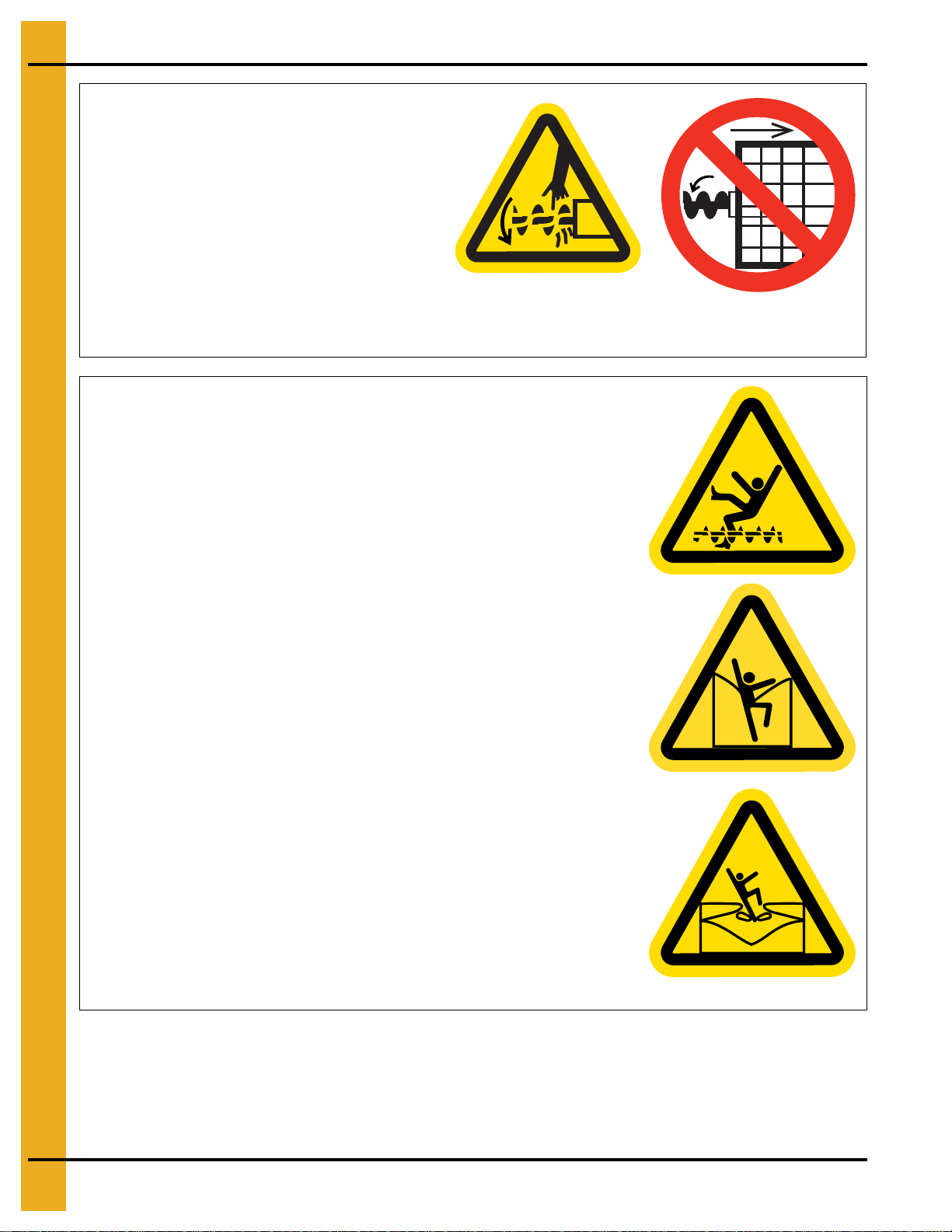
Safety Cautions ..................................................................................................................................... 6
Safety Sign-Off Sheet ......................................................................................................................... 10
Guidelines for Proper Storage of Grain Bin Materials Prior to Construction ....................................... 11
Chapter 2 Decals .................................................................................................................................. 12
Chapter 3 Hardware Requirements .................................................................................................... 14
Bolt Torque Specifications .................................................................................................................. 14
Chapter 4 Roof Assembly .................................................................................................................... 15
Installing the Roof Rafter Bracket to the Top Outside Stiffener .......................................................... 15
Installing the Eave Clip and Intermediate Eave Angle to the Sidewall Sheet ..................................... 18
Attaching the Peak Ring Attach Clips to the Rafter ............................................................................. 20
Attaching the Center Collar to Peak Ring Weldment .......................................................................... 21
Peak Ring/Center Collar Placement ................................................................................................... 22
Attaching the Rafter assembly to Roof Rafter Bracket ........................................................................ 23
Attaching the Rafter Assembly to Peak Ring Weldment ..................................................................... 24
Installing the Tension Rods ................................................................................................................. 25
Assembling the Purlin ......................................................................................................................... 26
Installation of the Roof Panel Support Clips ........................................................................................ 28
Attaching the Roof Panels ................................................................................................................... 29
Installing the Roof Flashing ................................................................................................................. 32
Roof Ring Location (Optional) ............................................................................................................. 34
Installing a Roof Ring .......................................................................................................................... 35
Chapter 5 Warranty .............................................................................................................................. 37

4 PNEG-2145 21' Diameter Gamma Roof Assembly Instructions
1. Safety
Safety Guidelines
Safety guidelines are general-to-specific safety rules that must be followed at all times. This manual is
written to help you understand safe operating procedures and problems that can be encountered by the
operator and other personnel when using this equipment. Save these safety guidelines for future
reference.
As owner or operator, you are responsible for understanding the requirements, hazards, and precautions
that exist and to inform others as required. Unqualified persons must stay out of the work area at all times.
Alterations must not be made to the equipment. Alterations can produce dangerous situations resulting in
SERIOUS INJURY or DEATH.
This equipment must be installed in accordance with the current installation codes and applicable
regulations,whichmustbecarefully followed inallcases. Authoritieshaving jurisdictionmustbe consulted
before installations are made.
When necessary, you must consider the installation location relative to electrical, fuel and water utilities.
Personnel operating or working around equipment must read this manual. This manual must be delivered
with equipment to its owner. Failure to read this manual and its safety instructions is a misuse of the
equipment.
ST-0001-3

1. Safety
PNEG-2145 21' Diameter Gamma Roof Assembly Instructions 5
Cautionary Symbols Definitions
Cautionary symbols appear in this manual and on product decals. The symbols alert the user of potential
safety hazards, prohibited activities and mandatory actions. To help you recognize this information, we
use the symbols that are defined below.
DANGER
WARNING
CAUTION
NOTICE
This symbol indicates an imminently hazardous situation
which, if not avoided, will result in serious injury or death.
This symbol indicates a potentially hazardous situation
which, if not avoided, can result in serious injury or death.
This symbol indicates a potentially hazardous situation which,
if not avoided, can result in minor or moderate injury.
This symbol is used to address practices not related to
personal injury.
This symbol indicates a general hazard.
This symbol indicates a prohibited activity.
This symbol indicates a mandatory action.
ST-0005-2

1. Safety
6 PNEG-2145 21' Diameter Gamma Roof Assembly Instructions
Safety Cautions
Use Personal Protective Equipment
Eye
Protection
Hearing
Protection
Hand
Protection
Head
Protection
Respiratory
Protection Foot
Protection
Fall
Protection
• Use appropriate personal protective equipment:
• Wear clothing appropriate to the job.
• Remove all jewelry.
• Tie long hair up and back.
ST-0004-1
Follow Safety Instructions
• Carefully read all safety messages in this manual and
safety signs on your machine. Keep signs in good
condition. Replace missing or damaged safety signs.
Be sure new equipment components and repair parts
include the current safety signs. Replacement safety
signs are available from the manufacturer.
• Learn how to operate the machine and how to use
controls properly. Do not let anyone operate without
instruction.
• If you do not understand any part of this manual or
need assistance, contact your dealer.
ST-0002-1
Maintain Equipment and Work Area
• Understand service procedures before doing work. Keep area
clean and dry.
• Never service equipment while it is operating. Keep hands, feet,
and clothing away from moving parts
• Keep your equipment in proper working condition. Replace worn
or broken parts immediately.
ST-0003-1

1. Safety
PNEG-2145 21' Diameter Gamma Roof Assembly Instructions 7
Prevent Roof Damage Due to Vacuum Pressure
• Roof damage can result from excessive vacuum or internal
pressure from fans or other air moving systems. The manufacturer
does not warrant this type of roof damage.
• Adequate ventilation or “makeup air” devices must be provided for
all powered air handling systems.
• The manufacturer does not recommend the use of downward flow
systems (suction).
• Severe roof damage can result from any blockage of air
passages.
• Running fans during high humidity or cold weather conditions can
cause air exhaust or intake ports to freeze.
ST-0028-2
Unload the Bin Correctly
• Use CENTER FLOOR OUTLET ONLY until NO grain
remains above this outlet.
• Side floor outlets to be used ONLY when above condition
is satisfied.
• Lock all side floor outlets to avoid accidental premature use.
• See manufacturers instructions for proper use of factory
supplied sidedraw (wall) discharge systems.
ST-0060-1
Sharp Edge Hazard
• This product has sharp edges, which can cause serious injury.
• To avoid injury, handle sharp edges with caution and always use
proper protective clothing and equipment.
ST-0036-2

1. Safety
8 PNEG-2145 21' Diameter Gamma Roof Assembly Instructions
Rotating Auger Hazard
• Keep clear of rotating augers and moving
parts.
• Do not remove or modify guards or
covers.
• Lock-out power source before making
adjustments, cleaning, or maintaining
equipment.
• Failure to follow these precautions will
result in serious injury or death.
ST-0037-1
Do Not Enter Bin
• Rotating flighting will kill or dismember.
• Flowing material will trap and suffocate.
• Crusted material will collapse and suffocate.
- If you must enter the bin:
1. Shut off and lock out all power sources.
2. Use a safety harness and safety line.
3. Station another person outside the bin.
4. Avoid the center of the bin.
5. Wear proper breathing equipment or respirator.
ST-0061-1

1. Safety
PNEG-2145 21' Diameter Gamma Roof Assembly Instructions 9
Stay Clear of Hoisted Equipment
• Always use proper lifting or hoisting equipment when
assembling or disassembling equipment.
• Do not walk or stand under hoisted equipment.
• Always use sturdy and stable supports when needed for
installation. Not following these safety precautions creates
the risk of falling equipment, which can crush personnel and
cause serious injury or death. ST-0047-1
Do Not Overfill the Bin
• Do not overfill bin. Stored grain must be no higher than
the roof eaves at the outer edge.
• Filling the bin above this point creates excessive internal
pressure and can cause swelling and eventual roof
failure. The over filling of a bin can also cause the
blockage of roof vents and eaves, which will lead to a
build-up of air pressure causing roof damage.
ST-0050-1
Install and Operate Equipment Properly
• This product is intended for the use of grain storage only. Any other
use is a misuse of the product.
ST-0057-1
Store Bin Sheets Properly
• Sidewall bundles or sheets must be stored in a safe manner.
The safest method of storing sidewall bundles is by laying them
horizontally with the arch of the sheet upward, like a dome.
• Sidewall sheets stored on edge must be secured so that they
cannot fall over and cause injury.
• Use care when handling and moving sidewall bundles.
ST-0058-1

1. Safety
10 PNEG-2145 21' Diameter Gamma Roof Assembly Instructions
Safety Sign-Off Sheet
Below is a sign-off sheet thatcan be used to verify that all personnel have read and understood the safety
instructions. This sign-off sheet is provided for your convenience and personal record keeping.
Date Employee Name Supervisor Name
ST-0007

1. Safety
PNEG-2145 21' Diameter Gamma Roof Assembly Instructions 11
Guidelines for Proper Storage of Grain Bin Materials Prior to
Construction
Storage of the build materials prior to construction is important. Do not to allow moisture to remain
between sheets or panels.
Wetstorage stain(rust)will developwhen closelypacked bundlesof galvanizedmaterial,such assidewall
and roof sheets, have moisture present. Inspect roof and sidewall bundles on arrival for any moisture. If
moisture is present, it must not be allowed to remain between the sheets. Separate the sheets or panels
immediately and wipe them down. Spray with a light oil or diesel fuel.
If possible, sidewall bundles, roof sheets and other closely packed galvanized materials should be stored
in a dry, climate controlled building. If outdoor storage is unavoidable, the materials should be stored so
that they are raised above the ground and vegetation. Any stacking and spacing materials should not be
corrosive or wet. Be sure to protect materials from the weather, but permit air movement around the
bundles if possible.
Storing roof bundles and sidewall sheets at a slight incline can also help minimize the presence of
moisture. Storing the bundles with the center of the dome up (like an arch) is one option for minimizing
moisture during storage. Sidewall bundles can also be stored on edge but must be secured so that they
do not fall over and cause injury.
If “white rust” or “wet storage stain” occurs, contact the manufacturer immediately about ways to minimize
the adverse effect upon the galvanized coating.

12 PNEG-2145 21' Diameter Gamma Roof Assembly Instructions
2. Decals
The safety decals on your equipment are safety indicators which must be carefully read and understood
by all personnel involved in the installation, operation, service and maintenance of the equipment.
To replace a damaged of missing decal, contact us to receive a free replacement.
GSI Decals
1004 E. Illinois St.
Assumption, IL. 62510
Phone: 1-217-226-4421
Location Decal # Decals Description
Located next to
aeration system. DC-969 Caution Vacuum
Pressure
Excessive vacuum (or pressure) may
damage roof. Use positive aeration
system. Make sure all roof vents are
open and unobstructed. Start roof
fans when supply fans are started.
Do not operate when conditions exist
that may cause roof vent icing.
DC-969
CAUTION
GSI Group, Inc. 217-226-4421

2. Decals
PNEG-2145 21' Diameter Gamma Roof Assembly Instructions 13
On bin door
covers DC-GBC-1A Danger Keep Clear
of Augers
On bin door
covers DC-GBC-2A Warning Unload
Instructions
Location Decal # Decals Description
Rotating flighting will
kill or dismember.
Flowing material will
trap and suffocate.
Crusted material will
collapse and suffocate.
DANGER
Keep clear of all augers.
DO NOT ENTER this bin!
If you must enter the bin:
1. Shut off and lock out all power.
2. Use a safety harness and safety line.
3. Station another person outside the bin.
4. Avoid the center of the bin.
5. Wear proper breathing equipment or respirator.
Failure to heed these
warnings will result in
serious injury or death.
DC-GBC-1A
GSI GROUP, INC. 217-226-4421
WARNING
GSI GROUP, INC. 217-226-4421
1. Use CENTER FLOOR OUTLET ONLY until NO grain
remains above this outlet.
2. Side floor outlets to be used ONLY when above
condition is satisfied.
3. Lock all side floor outlets to avoid accidental
premature use.
4. See manufacturers instructions for proper use of
factory supplied sidedraw (wall) discharge systems.
UNLOADING INSTRUCTIONS:
Failure to heed these warnings
could result in serious injury, death,
structural damage or collapse of tank.
DC-GBC-2A

14 PNEG-2145 21' Diameter Gamma Roof Assembly Instructions
3. Hardware Requirements
Bolt Torque Specifications
The specification torque table below will help the installer determine how tight a specific bolt must be.
A bolt that has been over tightened can be just as dangerous as one that has not been tightened enough.
IMPORTANT: Bolts should not be tightened in excess of the torque specifications chart listed below.
Bolt
Minimum Torque Minimum Torque
Sealing Joints
(Joints with
Sealing Washers)
Structural Joints
(Joints without
Sealing Washers)
Sealing Joints
(Joints with
Sealing Washers)
Structural Joints
(Joints without any
Sealing Washers)
ft./lbs. N-m ft./lbs. N-m ft./lbs. N-m ft./lbs. N-m
5/16"-18 JS Grade 8 with Seal 20 27 - -2534 - -
3/8"-16 JS Grade 8 with Seal 30 41 - - 35 47 - -
7/16"-14 JS Grade 8 with Seal 50 68 - -6060 - -
3/8"-16 YDP Grade 8 Flanged - - 40 54 - - 45 61
7/16"-14 YDP Grade 8 Flanged - - 65 88 - - 72 97
1/2"-13 YDP Grade 8 Flanged - - 100 135 - - 110 149

PNEG-2145 21' Diameter Gamma Roof Assembly Instructions 15
4. Roof Assembly
Installing the Roof Rafter Bracket to the Top Outside Stiffener
The roof rafter bracket is the vertical member which supports the rafter. It is installed to the inside
perimeter of the sidewall sheet at the same time as the top outside stiffener.
What You Should Know
NOTE: Do not tighten the nuts (C) until all hardware has been installed attaching the rafter bracket, to
the sidewall and the outside stiffener.
1. From the inside perimeter of the sidewall, place the bolt (B) to attach the rafter bracket (D) to
the top outside stiffener (A) through the hole located approximately 4" down from the top of the
sidewall sheet (G).
NOTE: Install the bolts from the inside to the outside of the bin, passing through the rafter bracket,
corrugation spacer, sealing washer, sidewall sheet and outside stiffener and flange nut.
NOTE: Make sure to install the bolts through every second hole from the top of the rafter bracket.
2. On the inside perimeter, install a sealing washer (F), corrugation spacer (E) and rafter bracket (D).
3. On the outside perimeter, install the outside top ring stiffener (A).
4. Tighten the hardware to the recommended torque specifications. See bolt torque specifications
on Page 14.
Figure 4A Installing the Roof Rafter Bracket to the Top Outside Stiffener (FC Stiffened Bins) - 4.00"
Ref # Part # Description Ref # Part # Description
AFC-42066XX 1 Ring Top Stiffener ES-7041 Corrugation Spacer
B S-7488 3/8" x 1-1/2" Flange Bolt F S-3558 Sealing Washer
CS-9426 3/8" Nut GSidewall Sheet
D CTR-1364 Roof Rafter Bracket H Assembled View

4. Roof Assembly
16 PNEG-2145 21' Diameter Gamma Roof Assembly Instructions
Figure 4B Installing the Roof Rafter Bracket to the Top Outside Stiffener (40-Series Stiffened Bins) - 4.00"
Ref # Part # Description
ACTS-2185XX 1 Ring Top Stiffener
B S-7488 3/8" x 1-1/2" Flange Bolt
CS-9426 3/8" Nut
D CTR-1364 Roof Rafter Bracket
ES-7041 Corrugation Spacer
F S-3558 Sealing Washer
GSidewall Sheet
H Assembled View

4. Roof Assembly
PNEG-2145 21' Diameter Gamma Roof Assembly Instructions 17
Figure 4C Installing the Roof Rafter Bracket to the Top Outside Stiffener (Universal Stiffened Bins) - 2.66"
Ref # Part # Description
ASS-7066XX 1 Ring Top Stiffener
B S-7488 3/8" x 1-1/2" Flange Bolt
CS-9426 3/8" Nut
D CTR-1364 Roof Rafter Bracket
ES-7041 Corrugation Spacer
F S-3558 Sealing Washer
GSidewall Sheet
H Assembled View
ISS-7064XX 1 Ring Offset Stiffener

4. Roof Assembly
18 PNEG-2145 21' Diameter Gamma Roof Assembly Instructions
Installing the Eave Clip and Intermediate Eave Angle to the
Sidewall Sheet
The eave clips and intermediate eave angles are installed onto the sidewall sheet to assemble the
roof panels.
1. Install the eave clips (B or F) to the sidewall sheet (E) with flange bolts (C) and flange nuts (D).
NOTE: Make sure to install the eave clips (B or F) to the inside of the sidewall sheet (E).
2. Install the intermediate eave angle (A) to the sidewall sheet (E) with flange bolts (C) and flange
nuts (D) between the two (2) eave clips (B or F).
NOTE: Make sure to install the intermediate eave angle (A) to the outside of the sidewall sheet (E)
for 4.00" bins. (See Figure 4D.)
NOTE: Make sure to install the intermediate eave angle (A) to the inside of the sidewall sheet (E)
for 2.66" bins. (See Figure 4E on Page 19.)
3. Repeat the process to continue installing the remaining eave clips (B or F) and intermediate eave
angles (A).
4. Tighten the hardware to the recommended torque specifications. See bolt torque specifications
on Page 14.
Figure 4D Installing the Eave Clip and Intermediate Eave Angle to the Sidewall Sheet for 4.00"
Ref # Part # Description Ref # Part # Description
ACTR-1183 Intermediate Eave Angle DS-3611 5/16" Flange Nut
B CTR-1201 Eave Clip E Sidewall Sheet
CS-10260 5/16" x 1" Flange Bolt

4. Roof Assembly
PNEG-2145 21' Diameter Gamma Roof Assembly Instructions 19
Figure 4E Installing the Reverse Rolled Eave Clip and Intermediate Eave Angle to the Sidewall Sheet for 2.66"
Ref # Part # Description
ACTR-1183 Intermediate Eave Angle
C S-10260 5/16" x 1" Flange Bolt
DS-3611 5/16" Flange Nut
E Sidewall Sheet
FCTR-1198 Reverse Rolled Eave Clip

4. Roof Assembly
20 PNEG-2145 21' Diameter Gamma Roof Assembly Instructions
Attaching the Peak Ring Attach Clips to the Rafter
Peak ring attach clips secure the rafter to the peak ring weldment.
What You Should Know
Each roof rafter receives two (2) peak ring attach clips.
1.Determine thecorrectorientationofeach rafter(A) byidentifying theroof panelholes(E)located near
the end of each rafter (A).
2. Install peak ring attach clips (B) to both sides of the roof rafter (A).
3. Use flange bolts (C) and flange nuts (D) to secure the peak ring attach clips (B) to the rafter (A).
Tighten to the recommended torque specification. See bolt torque specifications on Page 14.
Figure 4F Exploded View of Peak Ring Attach Clips
After You Finish
Repeat this process for the remaining roof rafters.
Ref # Part # Description
ACRP-7346 Roof Rafter
B CRP-6092 Peak Ring Attach Clip
CS-7487 3/8" x 1" Flange Bolt
D S-9426 3/8" Flange Nut
ERoof Panel Hole
Table of contents
Other GSi Accessories manuals
Popular Accessories manuals by other brands

Waterpik
Waterpik Water Flosser WP-560 quick start guide

Philio Technology Corporation
Philio Technology Corporation PSM08 manual

HumanTechnik
HumanTechnik lisa operating instructions

MICRO-EPSILON
MICRO-EPSILON surfaceCONTROL 3D instruction manual

Waterpik
Waterpik Pearl user manual

commercial cool
commercial cool CCB51GB user manual