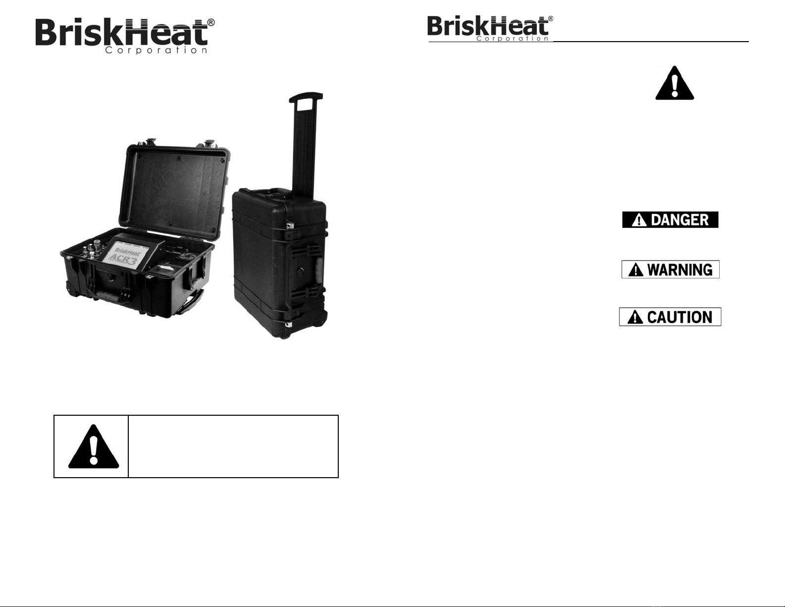
BriskHeat ACR 3 User manual

ACR®3 Hot Bonder
Instruction Manual
Read and understand this manual before operating or
servicing this temperature control system. Failure to
understand how to safely operate this controller could result
in an accident causing serious injury or death. Only qualified
personnel should operate or service this controller.
Language Page
English ...................................................................................................... 1
Spanish (Español) .................................................................................... 29
French (Français) ..................................................................................... 57
German (Deutsch) .................................................................................... 85
Italian (Italiano) ......................................................................................... 113
English
© BriskHeat® Corporation. All rights reserved.
2
ACR®3 Hot Bonder
TABLE OF CONTENTS
Safety Alert Symbol ............................................. 2
Important Safety Instructions .............................. 3
Introduction .......................................................... 4
Package Contents ................................................ 4
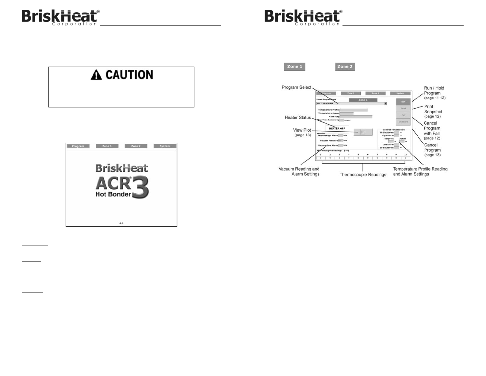
Getting to Know Your ACR®3 Hot Bonder .......... 5
Specifications ....................................................... 6
Equipment Setup and Start-up ............................ 7
Power Input ................................................... 7
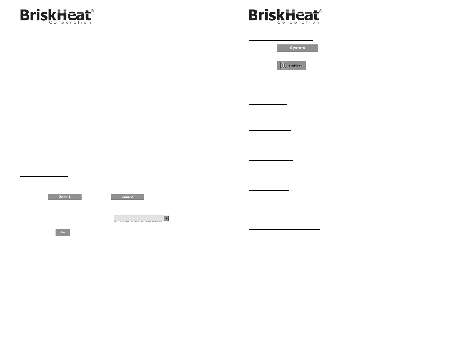
Starting Up .................................................... 7
Heater Output Power Cord Attachment ......... 7
Temperature Sensor Attachment ................... 8
Vacuum Hose Connect ................................. 8
Electric Pump ................................................ 8
Vacuum Venturi ............................................. 8
External Vacuum ........................................... 8
Touchscreen Operating Instructions .................. 9
Operating Menu 10
Starting a Program ........................................ 11
Safely Shut Down ACR®3 .............................. 12
Save a Log File ............................................. 12
Print a Snapshot ............................................ 12
Silence the Alarm .......................................... 12
Hold a Program ............................................. 12
Cancel a Program with a Fall ........................ 12
Cancel a Program ......................................... 13
View Plot ....................................................... 13
Alarms ........................................................... 14
Program Menu ................................................. 14
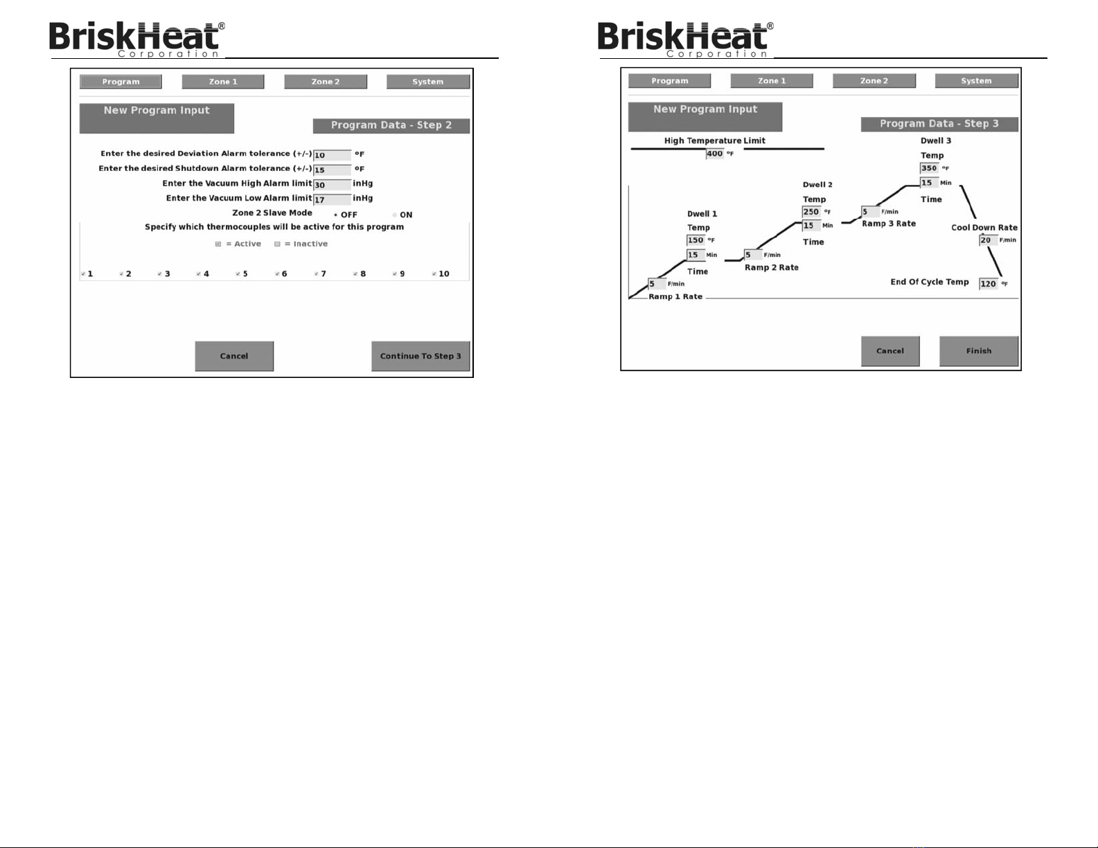
Write a New Program .................................... 15
Edit an Existing Program ............................... 19
Delete a Program .......................................... 19
Edit an Existing Program while Running ........ 20
Change Program Password .......................... 20
System Menu ................................................... 21
Save a Single Log File to USB Drive ............. 21
Save All Log Files to USB Drive .................... 22
Delete a Single Log File ................................ 22
Delete All Log Files ....................................... 22
Save a Single Program File to USB Drive ..... 23
Save All Program Files to USB Drive ............ 23
Load a Single Program File from USB Drive. 23
Load All Program Files from USB Drive......... 24
Shut Down System ........................................ 24
Change System Date and Time .................... 24
Change Language ......................................... 25
Change Administrator Password ................... 25
Delete All Program Passwords ...................... 26
Factory Settings ............................................ 26
Cleaning and Decontamination ........................... 26
Equipment Maintenance .....................................
26
Notes ..................................................................... 27
Warranty Information ........................................... 28
SAFETY ALERT SYMBOL
The symbol above is used to call your
attention to instructions concerning your
personal safety. It points out important safety
precautions. It means “ATTENTION!
Become Alert! Your Personal Safety is
involved!” Read the message that follows
and be alert to the possibility of personal
injury or death.
SAVE THESE INSTRUCTIONS!
Additional copies of this manual
are available upon request.
Immediate hazards which WILL result in
severe personal injury or death.
Hazards or unsafe practices that COULD
result in severe personal injury or death.
Hazards or unsafe practices that COULD
result in minor personal injury or property
damage.

© BriskHeat® Corporation. All rights reserved.
3
ACR®3 Hot Bonder
IMPORTANT SAFETY INSTRUCTIONS
Agency Approvals
Approval valid only when installed with UL listed
products.
DANGER
Do not immerse or spray hot bonder with liquid.
Keep volatile or combustible material away from
hot bonder when in use.
Use hot bonder only in approved locations.
Keep sharp metal objects away from hot bonder.
The operator is not to open the enclosure. Only a
trained service person may open the enclosure.
Disconnect the power cord before opening the
enclosure. Turning off the power switch leaves
dangerous voltage levels accessible to the service
person.
If the equipment is used in a manner not specified
by the manufacturer, the protection provided by
the equipment can be impaired.
The unit must be connected to Protective Earth
Grounding.
Failure to observe these warnings may result in electric
shock, risk of fire, and personal injury or death.
WARNING
End-User Must Comply to the Following:
Only qualified personnel are allowed to connect electrical wiring.
All electrical wiring must follow local electrical codes and highly recommend following NEC Article 427.
The end-user is responsible for providing a suitable disconnecting device.
The end-user is responsible for providing suitable electrical protection device. It is highly recommended that a
ground fault circuit breaker is used.
If a Protective Earth Conductor must be removed during service, it must be replaced.
Failure to observe these warnings may result in personal injury or damage to the heater.
CAUTION
Inspect hot bonder before use.
Do not use hot bonder if damaged.
Do not repair damaged or faulty hot bonders.
Do not position the equipment so that it is difficult
to operate the disconnect device. The power cord
is the disconnect device.
Do not crush or apply severe physical stress on
hot bonder or cord assembly.
Unplug hot bonder when not in use.
Only use power cords provided by BriskHeat®
Failure to observe these warnings may result in personal
injury or damage to the heater.
A person who has not read and
understood all operating
Instructions is not qualified to
operate this product.
DANGER WARNING
© BriskHeat® Corporation. All rights reserved.
4
ACR®3 Hot Bonder
INTRODUCTION
The BriskHeat® ACR®3 Hot Bonder is the world’s most complete, all-in-one equipment to
debulk and cure resins, prepregs, adhesives, fibers, and more. This equipment controls the
heat and vacuum for on-the-spot composite and metal bond repairs / cures. These systems
are portable and self-contained. For successful operation of this system, read and understand
these instructions prior to use.
PACKAGE CONTENTS
ACR®3 Hot Bonder unit
An accessory storage case containing:
One 10ft (3m) input power cord with plug per zone (20937-120 or 20937-240)
One 5ft (1.5m) heater output power cord per zone (20936-01)
10 J-type thermocouples with mini connectors per zone (11510)
10 Standard connector adapters for thermocouple receptacles per zone (41253)
Two 10ft (3m) vacuum hoses per zone (20938)
Two vacuum bag feed-throughs per zone (20931)
One extra printer ribbon (40795-02) and roll of printer paper (40795-01) per zone
USB flash disk (11514-03)
If any items are missing from the package, call your local distributor or BriskHeat®at
(800) 848-7673 (U.S. and Canada) or (614) 294-3376.

© BriskHeat® Corporation. All rights reserved.
5
ACR®3 Hot Bonder
GETTING TO KNOW YOUR ACR® 3 HOT BONDER
Full-Color Touchscreen Interface ype J Thermocouple
Main Power Switch and Circuit
Breaker Switches
Inputs Vacuum Hose Inputs, Vacuum
Adjustments, and Vacuum Pump
Switch.
Power Input Receptacles Printer and Printer Feed Button
Heater Output Receptacles USB Data Port
© BriskHeat® Corporation. All rights reserved.
6
ACR®3 Hot Bonder
SPECIFICATIONS
General
Single or dual zone
8.4” (213mm) touch screen with easy-to-use interface
USB port for data transfer
Input ground fault interrupter breaker protected
Audible and visual alarms for high and low temperature / vacuum limits
Power
Input Voltage: 100-130VAC, 200-240VAC
MAINS supply voltage fluctuations up to ±10% of the nominal voltage
Transient overvoltages typically found on a Category II power source: i.e. a lighting circuit
Frequency: 50/60Hz
30 amps maximum per zone
Maximum output rating: 240VAC, Single Phase
Environment
Intended for use in dry environments. Do not expose to spray
Altitude up to 6562ft (2000m)
Storage temperature range: -4°F to 140°F (-20°C to 60°C)
Operating temperature range: 41°F to 104°F (5°C to 40°C)
Maximum relative humidity: 80% for temperatures up to 88°F (31°C) decreasing linearly to
50% relative humidity at 104°F (40°C)
Pollution Degree 2 (Normally only non-conductive pollution occurs, however a temporary
conductivity caused by condensation must be expected)
Vacuum
Pressure: 27-28in Hg (13.26-13.75PSI)
Flow: 5.7 scfm (Vacuum Venturi)
0.9 scfm (Electric Vacuum Pump)
Ability to manually adjust pressure for each zone
Temperature Control
Cures up to 1400°F (760°C)
10 thermocouple sensor inputs per zone
Accepts mini Type J thermocouple connectors

© BriskHeat® Corporation. All rights reserved.
7
ACR®3 Hot Bonder
VOLTAGE:
100-130, 200-240VAC
Read and understand this entire manual before
operating this hot bonder.
EQUIPMENT SETUP AND START-UP
Power Input
1. For the ACR®3 to operate, power must be supplied to Zone 1. Power only needs to be
applied to Zone 2 if that zone will be used for a cure.
2. Locate the surface mount connector labeled POWER INPUT on the front panel of the ACR®3.
3. Align the power cord connector with the surface mount connector and insert. The power input
cord connectors are keyed to prevent improper connections.
4. Turn the locking ring clockwise 1/2 turn to lock the cord into place. The power cord must be
fully inserted and locked for proper operation.
5. Connect the power input cord to the properly rated power supply.
Each Zone must be plugged into its own dedicated 30A branch circuit.
Starting Up
1. Flip the circuit breaker switches to the ON position.
2. Flip the red main power switch to the ON position. The main power switch illuminates when
on.
The system goes through a boot-up cycle. At the end of the boot up cycle, the printer prints the
message “PRINTER READY”.
Heater Output Power Cord Attachment
1. Locate the surface mount connector labeled HEATING POWER for the specific zone to be
used on the front panel of the ACR®3.
2. Align the cord connector with the surface mount connector and insert. The connectors are
keyed to prevent improper connections.
3. Turn the locking ring clockwise 1/2 turn to lock the cord into place. The cord must be fully
inserted and locked for proper operation.
© BriskHeat® Corporation. All rights reserved.
8
ACR®3 Hot Bonder
Temperature Sensor Attachment
The ACR®3 Hot Bonder uses Type J thermocouples for temperature input. There are 10 sensor
inputs per zone.
Connect thermocouple sensors as required. The program to be run will determine the number of
sensors necessary.
Vacuum Hose Connect
The ACR®3 requires two vacuum hoses per zone for proper vacuum operation. One hose is for
the vacuum source. The second hose is for vacuum monitoring. To assure proper vacuum levels,
the two hoses must be attached to the vacuum bag / repair area as far apart as possible.
The vacuum connectors are self-sealing and designed for quick disconnect allowing it to be
operated by one hand.
1. Attach the female end of the vacuum source hose the port marked VAC. CONNECT and the
other to one of the vacuum ports on the repair.
2. Attach the female end of the vacuum monitor hose to the port marked VAC MONITOR and
the male end to the second vacuum feed- through on the repair.
3. The vacuum level can be adjusted independently for each zone. Turn the VAC. ADJUST
valve counter clockwise to decrease that vacuum level and clockwise to increase the vacuum
level.
Electric Pump
Each zone has its own electric pump. To turn on the built-in electric vacuum pump, flip the green
PUMP ON/OFF switch to on. The switch illuminates when activated. To turn the pump off, flip the
green PUMP ON/OFF switch to off. The switch will no longer be illuminated.
Vacuum Venturi
The vacuum venturi converts compressed air to vacuum.
1. Attach a compressed air source to the AIR INLET port. The air must be clean and dry to
avoid problems with the Venturi system. It is recommended to utilize an in line filter system for
the compressed air.
2. Adjust the inlet air pressure to 80 PSI.
External Vacuum
The ACR®3 has the option of using an external vacuum source. To use, connect an external
vacuum source to the EXTERNAL VACUUM port.

© BriskHeat® Corporation. All rights reserved.
9
ACR®3 Hot Bonder
TOUCHSCREEN OPERATING INSTRUCTIONS
All commands for the touchscreen interface can be made by touching the screen with your finger
or a touchscreen-safe stylus.
Introduction:
The opening screen has the following buttons: PROGRAM, ZONE 1, ZONE 2 (if applicable), and
SYSTEM. It also displays the software version number.
PROGRAM: In this menu you can write a new program, make changes to an existing program,
add or remove a program’s password protection, view a program’s profile, or delete a program.
ZONE 1: In this menu you can run a stored program for Zone 1, view the current status of a
program, and view a plot display of a running program.
ZONE 2 (if applicable): In this menu you can run a stored program for Zone 2, view the current
status of a program, and view a plot display of a running program.
SYSTEM: In this menu you can access password administrative settings, save log files to a USB
drive, save programs to a USB drive, load programs from a USB drive, change system date &
time, change language, and safely shutdown hot bonder.
Software Version Number: The newest version of the ACR®3 software can be found at
www.briskheat.com.
Do not touch touchscreen with sharp objects or marking objects such
as pens, pencils, markers, etc. These objects cause irreversible
damage to the touchscreen.
© BriskHeat® Corporation. All rights reserved.
10
ACR®3 Hot Bonder
Operating menu
From this menu you can start a program, save a log file, hold a program, cancel a program,
cancel a program with a fall, and view a graphical plot.
Touch button or at top of screen to access the Operating menu.
Temperature Profile:
Displays the current running program profile: Fixed, Single, Dual, Triple, or Monitor
Temperature Source:
Displays the current running program temperature source: Average, Highest, Lowest,
or specific
Cure Step:
Displays the current active step of running program
Step Time Remaining:
Displays the calculated length of time remaining for the current running program
Vacuum Reading and Alarm Settings
Vacuum High Alarm:
Displays the high vacuum alarm set point
Vacuum Pressure:
Displays the actual vacuum measured
Vacuum Low Alarm:
Displays the low vacuum alarm set point

© BriskHeat® Corporation. All rights reserved.
11
ACR®3 Hot Bonder
Temperature Profile Reading and Alarm Settings
High Shutdown:
Displays the high temperature shutdown set point
High Alarm:
Displays the high alarm set point
Set point:
Displays the current system set point
Actual:
Displays the current actual control temperature as measured or calculated
Low Alarm:
Displays the low alarm set point
Low Shutdown:
Displays the low temperature shutdown set point
Thermocouple Readings
Displays the actual temperature of each individual sensor. A grey field indicates a disabled
sensor. A red field indicates a faulty input: i.e. open, high temperature, or low temperature.
Starting a program:
1. Attach the necessary cords, sensors and hoses as described in Equipment Setup and Start-
up on page 7.
2. Touch button or at top of screen to access
the OPERATING menu.
3. Select the program from the drop down list .
Note: See page 15 for instructions on how to Write a New Program.
4. Touch the button. The Repair Data screen displays.
5. Enter the necessary repair data or skip by pressing ENTER.
6. To enter the repair data, touch the data field to be entered.
7. Using the keyboard on the data entry screen, enter the required data and touch ENTER.
8. When all necessary data has been entered, press the ENTER button and the program starts.
© BriskHeat® Corporation. All rights reserved.
12
ACR®3 Hot Bonder
Safely Shut Down ACR® 3:
1. Touch button at the top of the screen to access the SYSTEM
menu.
2. Touch button.
3. Press OK to shut down hot bonder.
4. Flip the red main power switch to the OFF position. The main power switch is not illuminated
when off.
Save a Log File:
1. After successful run, Press YES button to save log file and data. Press NO button to exit
without saving.
Print a Snapshot:
This function prints a snap shot of the cure cycle.
1. Touch PRINT button in the OPERATING menu to print snapshot of cure cycle.
Silence the Alarm:
This function silences the audible alarm.
1. Touch ALARM button in upper right screen that appears after audible alarm starts.
Hold a Program:
This function holds / pauses a program after it has begun.
1. Touch HOLD button in the OPERATING menu to hold a program.
2. Touch RUN button in the OPERATING menu to resume program.
Cancel a Program with a Fall:
This function allows you to cancel a program with a gradual fall.
1. Touch FALL button in the OPERATING menu to cancel program with a fall.
2. Press YES button to save log file and data. Press NO button to exit without saving.

© BriskHeat® Corporation. All rights reserved.
13
ACR®3 Hot Bonder
Cancel a Program:
This function cancels a program prior to its completion.
1. Touch END CURE button in the OPERATING menu to cancel running program.
2. Press YES button to save log file and data. Press NO button to exit without saving.
View Plot:
This function views a graphical plot of current activity. The graphical plot shows actual
temperature, target temperature, high and low alarms. To switch between normal and zoomed
view, touch the ZOOM button.
1. Touch button in the OPERATING menu to view plot.
Explanation of Lines
Black - Actual Plot
Dotted Green - Target Plot
Blue - Time Corrected Target Plot. Time is corrected when either:
1 . Hot bonder is unable to achieve ramp up or down at targeted rate OR
2 . User places program on hold.
Purple - High / Low Deviation Alarm Limit
Red - High / Low Shut Down Alarm Limit
2. Touch or at top of screen to return to
zone operating screen.
© BriskHeat® Corporation. All rights reserved.
14
ACR®3 Hot Bonder
Alarms:
If all conditions are inside the programmed limits while a zone is running, the zone tab is green.
If while running, any condition exceeds programmed limits, the zone tab turns red.
If a variable exceeds a programmed limit, the display field of the variable turns red and a flashing
red alarm box appears in the zone screen. Touching the red alarm box silences the audible
alarm. The red alarm box and the red variable field remains red until the alarm condition is
corrected.
Program menu
From this menu, you can write a new program, add or remove a program’s password protection,
view a program’s profile, or delete a program.
Touch button at top of screen to access the PROGRAM menu.
Programs can be written or changed at any time even when the program is running. Changes to
an active program do not take place until the active zone is restarted. For additional information
see Edit an Existing Program While Running on page 20.
See page 19 for instructions to edit existing program parameters.

© BriskHeat® Corporation. All rights reserved.
15
ACR®3 Hot Bonder
Write a New Program:
This function designs and creates a curing / debulking program to the specific requirements of
your process.
1. Enter the new program mode by pressing the button at the right of the screen.
2. Enter the program name. Touch the program name field and the program name entry screen
opens. The program name can be any combination from 1 to 48 characters. Press ENTER
once to complete.
NOTE: If a duplicate name is entered, a warning displays and a default name is given using
the current date and time.
3. If the program is to be password protected press the YES button at the end of the question
“Do you want to password protect the program?” After pressing YES, the password entry
field appears.
4. To enter a password: touch the password field, enter the password, and then press enter.
5. Select the desired temperature profile: FIXED, SINGLE, DUAL, TRIPLE, or MONITOR.
© BriskHeat® Corporation. All rights reserved.
16
ACR®3 Hot Bonder
FIXED: The hot bonder ramps to this point as quickly as possible and holds until
changed by the operator.
SINGLE: The hot bonder ramps once to a single set point, holds for the programmed
length of time then ramps down.
DUAL: The hot bonder ramps once to a first set point, holds for the programmed
length of time, ramps to a second set point, holds for the programmed length of time,
then ramps down.
TRIPLE: The hot bonder ramps once to a first set point, holds for the programmed
length of time, ramps to a second set point, holds for the programmed length of time,
ramps to a third set point, holds for the programmed length of time, then ramps
down.
MONITOR: The hot bonder records input readings.
6. Select the temperature measurement source. The source can be AVERAGE, LOWEST,
HIGHEST, or any specific thermocouple.
AVERAGE: This mode uses a mathematical average of all active temperature inputs
as the control temperature.
LOWEST: This mode uses the lowest active thermocouple as the control
temperature.
HIGHEST: This mode uses the highest active thermocouple as the control
temperature.
SPECIFIC: Any active thermocouple, T/C 1 to T/C 10, can be selected as the control
sensor.
7. Select the temperature units by touching either Deg F or Deg C.
8. Select the vacuum pressure units by touching inHg for inches of mercury, mmHg for
millimeters of mercury, or mBar for millibars.
9. Set printer mode to ON or OFF as required.
10. Set data logging interval from 1 to 99 minutes.
NOTE: The data logging interval applies to both the printer output and to the file saved in
the internal memory of theACR®3.
11. Press the CONTINUE TO STEP 2 button.

© BriskHeat® Corporation. All rights reserved.
17
ACR®3 Hot Bonder
12. Enter the desired deviation alarm tolerance. The deviation alarm is an alarm point that
changes with the temperature set point. If this alarm point is exceeded, the alarm horn
sounds and ALARM displays in the zone operating screen.
13. Enter the desired shutdown alarm tolerance. The shutdown alarm is an alarm point that
changes with the temperature set point. If this alarm point is exceeded, the alarm horn
sounds and the controller aborts the cure cycle. A notification of the cycle abort displays in
the zone screen.
14. Enter the vacuum high and low alarm set points. The alarm sounds and ALARM displays in
the zone operating screen if either of these points are exceeded. Exceeding either of the
vacuum alarm points does not cause the controller to abort the cure cycle.
15. Set Zone 2 Slave Mode to ON or OFF (dual zone units only). Setting the slave mode to ON
assigns all 20 thermocouples to Zone 1.
16. Specify active and inactive thermocouples. Active thermocouples are indicated by a check
mark in the check box next the corresponding thermocouple number. Touch the check boxes
to remove the check mark from the inactive thermocouples.
17. Press the CONTINUE TO STEP 3 button.!
© BriskHeat® Corporation. All rights reserved.
18
ACR®3 Hot Bonder
18. Fill in all fields to the desired setting. Touch FINISH when complete:
Ramp Rate: the heat up rate in degrees per minute from starting temperature to
Dwell Temperature.
Dwell Temp: the temperature the program is to hold for the programmed length of
time.
Dwell Time: the length of time to hold at the programmed Dwell Temperature.
Cool Down Rate: the rate in degrees per minute from the last dwell temperature to
the End of Cycle Temp.
NOTE: Since the Hot Bonder cannot force an object to cool down faster than the
physical conditions will allow, both high temperature alarms are disabled during
the cool down phase.
End of Cycle Temp: the temperature at which the cure is considered complete.
NOTE: The end of cycle temperature must be above the ambient temperature for it to
complete.

© BriskHeat® Corporation. All rights reserved.
19
ACR®3 Hot Bonder
High Temperature Limit: allows the administrator to set a limit which any user will
not be able to exceed while writing programs. This safety feature is used to protect
the facilities equipment and the items being repaired. This variable can only be
changed in the program screen. Upon completing the high temperature limit change,
clear out the administrator password before rebooting. Requires administrator
password.
NOTE: This feature will change the high temperature limit inALL programs/recipes.
Edit an Existing Program:
This function makes changes to an existing program.
Programs can be written or changed at any time even when the program is running. Changes to
an active program do not take place until the active zone is restarted. For additional information
see Edit an Existing Program While Running on page 20.
1. Access the PROGRAM menu.
2. Select the program to edit by touching the drop down menu for STORED PROGRAM NAME.
3. Make changes to the following settings by touching the necessary field.
4. Touch SAVE button to save changes.
NOTE: The only parameter of a program that cannot be changed is the program name.
Delete a Program:
1. Access the PROGRAM menu.
2. Select the program to delete by touching the drop down menu for STORED PROGRAM
NAME.
3. Touch DELETE button to delete program.
4. Touch YES to confirm.
Thermocouple source
Data logging interval
Thermocouple settings!
Shutdown alarm temperature
Deviation alarm temperature
Vacuum pressure high-limit &!low-limit
alarm settings!
© BriskHeat® Corporation. All rights reserved.
20
ACR®3 Hot Bonder
Edit an Existing Program While Running:
Programs can be written or changed at any time even when the program is running. Changes
to an active program do not take place until the active zone is restarted.
1. Change the program to the desired parameters by following the steps in Edit an Existing
Program on page 19.
2. Select the zone to be reset by touching either .
3. In the zone operating screen, touch the HOLD button.
4. Press the RUN button. The cure step field returns to the previous active step of the program
and the printer, if active, prints out the new program.
NOTE: Changes to completed portions of a running program does not take effect until the
next time the program is ran. For example, if changes are being made to step one
of a two-step program and the program has already started into the second step, the
change does not take place until the next time the program is ran.
Change Program Password:
This function changes a program password. You must know the current password. If current
password is not known, refer to the SYSTEM menu section of this manual for assistance.
1. Access the PROGRAM menu.
2. Touch the STORED PROGRAM NAME field. Select the program to change password
protection.
3. Touch the CHANGE PASSWORD button.
4. Enter all required password information in the provided fields on screen. Touch OK button
when finished.

© BriskHeat® Corporation. All rights reserved.
21
ACR®3 Hot Bonder
SYSTEM MENU
From this menu, you can save log files to a USB drive, save programs to a USB drive, load
programs from a USB drive, access password administration settings, change system date &
time, change language, and shutdown system.
Touch button to access the SYSTEM menu.
Save
a Single Log File to USB Drive:
This function saves a single log file to a USB flash disk (thumb drive). This data can be
transferred to a PC for analysis or archiving.
NOTE: The ACR®3 Hot Bonder is capable of storing up to the 12 most recent log files in its
internal memory.
1. Access the SYSTEM menu.
2. Touch SAVE LOG FILES TO USB DRIVE button.
3. Select the desired log file from the drop down menu.
4. Touch COPY SELECTED FILES button.
5. Insert USB flash drive (thumb drive) in USB port located on the operator console. Touch OK
button.
6. Follow remaining on-screen commands.
Password
Administrative
(page 25)
Save / Delete
Log Files to USB
(page 21-22)
Save Programs
to USB
(page 23)
Load Programs
from USB
(page 23-24) Factory Settings
(page 26)
Shut Down System
(page 24)
Change Language
(page 25)
Change System
Date and Time
(page 24)
© BriskHeat® Corporation. All rights reserved.
22
ACR®3 Hot Bonder
Save All Log Files to USB Drive:
This function saves all stored log files to a USB flash disk (thumb drive). This data can be
transferred to a PC for analysis or archiving.
NOTE: The ACR®3 Hot Bonder is capable of storing up to the 12 most recent log files in its
internal memory.
1. Access the SYSTEM menu.
2. Touch SAVE LOG FILES TO USB DRIVE button.
3. Touch COPY ALL FILES button.
4. Insert USB flash drive (thumb drive) in USB port located on the operator console. Touch OK
button.
5. Follow remaining on-screen commands.
Delete a Single Log File:
This function deletes a single log file.
NOTE: The ACR®3 Hot Bonder is capable of storing up to the 12 most recent log files in its
internal memory.
1. Access the SYSTEM menu.
2. Touch SAVE LOG FILES TO USB DRIVE button.
3. Select the desired log file from the drop down menu.
4. Touch DELETE SELECTED FILES button.
5. Touch OK button to confirm.
Delete All Log Files:
This function deletes all stored log files.
NOTE: The ACR®3 Hot Bonder is capable of storing up to the 12 most recent log files in its
internal memory.
1. Access the SYSTEM menu.
2. Touch SAVE LOG FILES TO USB DRIVE button.
3. Touch DELETE ALL FILES button.
4. Touch OK button to confirm.

© BriskHeat® Corporation. All rights reserved.
23
ACR®3 Hot Bonder
Save a Single Program File to USB Drive:
This function saves a single program file to a USB flash disk (thumb drive). Use the USB
flash disk to transfer programs to another hot bonder or archive programs.
1. Access the SYSTEM menu.
2. Touch SAVE PROGRAMS TO USB DRIVE button.
3. Select the desired program file from the drop down menu.
4. Touch SAVE SELECTED PROGRAM TO USB DRIVE button.
5. Insert USB flash drive (thumb drive) in USB port located on the operator console. Touch OK
button.
6. Follow remaining on-screen commands.
Save All Program Files to USB Drive:
This function saves all stored program files to a USB flash disk (thumb drive). Use the USB flash
disk to transfer programs to another hot bonder or archive programs.
1. Access the SYSTEM menu.
2. Touch SAVE PROGRAM TO USB DRIVE button.
3. Touch SAVE ALL PROGRAMS TO USB DRIVE button.
4. Insert USB flash drive (thumb drive) in USB port located on the operator console. Touch OK
button.
5. Follow remaining on-screen commands.
Load a Single Program File from USB Drive:
This function loads a single program from a USB flash disk (thumb drive) to your hot bonder.
NOTE: The ACR®3 Hot Bonder is capable of storing up to 30 programs in its internal
memory.
1. Access the SYSTEM menu.
2. Touch LOAD PROGRAMS FROM USB DRIVE button.
3. Insert USB flash drive (thumb drive) in USB port located on the operator console. Touch OK
button.
4. Select the desired program file from the drop down menu.
5. Touch LOAD SELECTED PROGRAM FROM USB DRIVE button.
6. Follow remaining on-screen commands.
© BriskHeat® Corporation. All rights reserved.
24
ACR®3 Hot Bonder
Load All Program Files from USB Drive:
This function loads all stored programs from a USB flash disk (thumb drive) to your hot bonder.
NOTE: The ACR®3 Hot Bonder is capable of storing up to 30 programs in its internal
memory.
1. Access the SYSTEM menu.
2. Touch LOAD PROGRAMS FROM USB DRIVE button.
3. Touch LOAD ALL PROGRAM FROM USB DRIVE button.
4. Insert USB flash drive (thumb drive) in USB port located on the operator console. Touch OK
button.
5. Follow remaining on-screen commands.
Shut Down System:
This function safely shuts down the ACR®3. This function is recommended to provide optimal
performance.
1. Access the SYSTEM menu.
2. Touch button.
3. Press OK to shut down hot bonder.
4. Flip the red main power switch to the OFF position. The main power switch is not illuminated
when off.
Change System Date and Time:
1. Access the SYSTEM menu.
2. In the DATE / TIME SETUP section of the SYSTEM menu, touch the desired field. Enter the
new date / time.
3. Touch LOAD NEW DATE / TIME button.

© BriskHeat® Corporation. All rights reserved.
25
ACR®3 Hot Bonder
Change Language:
This function changes the displayed language. The ACR®3 displays either English or German
(Deutsch).
NOTE: This function requires a shut down and reboot.
1. Access the SYSTEM menu.
2. Touch LANGUAGE, SPRACHE button.
3. Select either English, Deutsch, or Cancel.
4. Press OK to shut down hot bonder.
5. Flip the red main power switch to the OFF position. The main power switch is not illuminated
when off.
6. Flip the red main power switch to the ON position. The main power switch is illuminated when
on.
7. Software now displays desired language.
Change Administrator Password:
This function permanently changes the administrator password: Requires administrator
password.
1. Touch the SYSTEM tab at the top of the screen.
2. Touch the PASSWORD ADMINISTRATION button.
3. Touch the ENTER ADMINISTRATOR PASSWORD field. A keyboard screen appears.
4. Type your administrator password. Touch the ENTER button when complete.
NOTE: Factory default password is “3-RCA”.
5. Touch the ENTER NEW PASSWORD field. A keyboard screen appears.
6. Type your new administrator password. Touch the ENTER button when done.
7. Touch the RE-ENTER NEW PASSWORD field. A keyboard screen appears.
8. Re-type your new administrator password. Touch the ENTER button when done.
9. Touch the UPDATE ADMIN PASSWORD button.
NOTE: System is in administrator mode until the hot bonder is shut down. See Shut Down
System on page 24 to shut down system.
© BriskHeat® Corporation. All rights reserved.
26
ACR®3 Hot Bonder
Delete All Program Passwords:
This function deletes all program passwords stored in the ACR®3. Requires administrator
password.
1. Touch the SYSTEM tab at the top of the screen.
2. Touch the PASSWORD ADMINISTRATION button.
3. Touch the ENTER ADMINISTRATOR PASSWORD field. A keyboard screen appears.
4. Type your administrator password. Touch the ENTER button when complete.
NOTE: Factory default password is “BHT”.
5. Touch the DELETE ALL PROGRAM PASSWORDS button.
6. Touch OK button to confirm.
NOTE: System is in administrator mode until the hot bonder is shut down. See Shut Down
System on page 24 to shut down system.
Factory Settings:
This function is for BriskHeat® factory only. It sets up the initial parameters.
CLEANING AND DECONTAMINATION
Clean only with a damp cloth and mild detergent, exterior only. No water should penetrate the
enclosure.
EQUIPMENT MAINTENANCE
Return to factory for repair, annual calibration, or maintenance. Contact factory at 1-800-848-7673
(toll free, U.S. / Canada) or 614-294-3376 for complete details.

© BriskHeat® Corporation. All rights reserved.
27
ACR®3 Hot Bonder
Notes:
© BriskHeat® Corporation. All rights reserved.
28
ACR®3 Hot Bonder
4800 Hilton Corporate Dr. Columbus, OH 43232
Toll Free: 800-848-7673
Phone: 614-294-3376
Fax: 614-294-3807
Email: bhtsales1@briskheat.com
WARRANTY INFORMATION
BriskHeat warrants to the original purchaser of this product for the period of twenty-four (24)
months. BriskHeat’s obligation and the exclusive remedy under this warranty shall be limited to
the repair or replacement, at BriskHeat’s option, of any parts of the product which may prove
defective under prescribed use and service following BriskHeat’s examination, is determined by
BriskHeat to be defective. The complete details of the warranty can be found online at
www.briskheat.com or by contacting us at 1-800-848-7673 (toll free, U.S. / Canada) or 1-614-294-
3376 (Worldwide).

29
Antes de operar o realizar mantenimiento de este sistema
de control de temperatura, lea y comprenda este manual. Si
no logra entender cómo operar con seguridad el
controlador, se podría producir un accidente que cause
lesiones graves o la muerte. Solamente personal cualificado
debería operar o realizar mantenimiento de este
controlador.
Dispositivo de adhesión
por calor ACR®3
Manual de instrucciones
Spanish (Español)
© BriskHeat® Corporation. Todos los derechos reservados.
30
Dispositivo de adhesión por calor ACR®3
¡CONSERVE ESTAS INSTRUCCIONES!
Existen copias adicionales de este manual
si lo solicita.
Peligros inmediatos que RESULTARÁN en
lesiones personales o muerte.
Peligros o prácticas no seguras que
PODRÍAN resultar en lesiones
personales graves o muerte.
Peligros o prácticas no seguras que
PODRÍAN resultar en lesiones
personales leves o daños a la propiedad.
SÍMBOLO DE ALERTA DE
SEGURIDAD
El símbolo de arriba se usa para que
preste atención a instrucciones que
conciernen a la seguridad personal. Indica
precauciones importantes relativas a la
seguridad. Significa “¡ATENCIÓN! ¡Esté
alerta! ¡Su seguridad personal está en
riesgo!” Lea el mensaje que sigue y esté
alerta a la posibilidad de lesiones
personales o riesgo de muerte.
PRECAUCIÓN
ADVERTENCIA
PELIGRO
ÍNDICE
Símbolo de alerta de seguridad ............................................ 30
Instrucciones importantes de seguridad ............................. 31
Introducción ............................................................................ 32
Contenido del paquete .......................................................... 32
Familiarización con el dispositivo de
adhesión por calor ACR®3 .................................................... 33
Especificaciones .................................................................... 34
Configuración y puesta en marcha del equipo .................... 35
Entrada de alimentación ................................................. 35
Arranque ......................................................................... 35
Aditamento de cable de alimentación en la salida del
calentador ....................................................................... 35
Aditamento de sensor de temperatura ........................... 3 6
Conexión de la manguera de vacío ................................ 36
Bomba eléctrica .............................................................. 36
Vacío Venturi .................................................................. 36
Vacío externo ................................................................. 36
Instrucciones de funcionamiento de la pantalla táctil ......... 3 7
Menú de funcionamiento .................................................. 38
Iniciar un programa......................................................... 39
Apagar con seguridad el ACR®3 .................................... 40
Guardar un archivo de registro ....................................... 40
Imprimir una instantánea ................................................ 40
Silenciar la alarma .......................................................... 40
Hold a Program .............................................................. 40
Poner un programa en suspensión ................................ 40
Cancelar un programa .................................................... 41
Ver diagrama .................................................................. 41
Alarmas .......................................................................... 42
Menú de programas ........................................................... 42
Escribir un nuevo programa ........................................... 43
Editar un programa existente ......................................... 47
Eliminar un programa ..................................................... 47
Editar un programa existente mientras está en
funcionamiento ............................................................... 48
Cambiar la contraseña del programa ............................. 48
Menú del sistema ............................................................... 49
Guardar un solo archivo de registro en u nidad USB ..... 49
Guardar todos los archivos de registro en unidad USB .. 50
Eliminar un solo archivo de registro ............................... 50
Eliminar todos los archivos de registro ........................... 50
Guardar un solo archivo de programa en unidad USB ... 51
Guardar todos los archivos de programa en
unidad USB .................................................................... 51
Cargar un solo archivo de programa desde la
unidad USB. ................................................................... 51
Load All Program Files from USB DriveCargar todos
los archivos de programa desde la unidad USB ............. 52
Apagar el sistema ........................................................... 52
Fecha y hora del sistema cambio ................................... 52
Cambiar idioma .............................................................. 53
Cambiar la contraseña de administrador ........................ 5 3
Eliminar todas las contraseñas de programas ................ 54
Configuración de fábrica ................................................. 54
Limpieza y descontaminación ............................................... 54
Mantenimiento del equipo ...................................................... 54
Notas ........................................................................................ 55
Información sobre la garantía ................................................ 56

© BriskHeat® Corporation. Todos los derechos reservados.
31
Dispositivo de adhesión por calor ACR®3
No sumerja ni rocíe el dispositivo de adhesión por
calor con líquido.
Mantenga material volátil o combustible lejos del
dispositivo de adhesión por calor cuando se está
utilizando.
Utilice el dispositivo de adhesión por calor
solamente en los lugares aprobados.
Mantenga los objetos metálicos afilados lejos del
dispositivo de adhesión por calor.
El operador no debe abrir la carcasa. Solamente
personal de servicio capacitado puede abrir la
carcasa.
Desconecte el cable de alimentación antes de
abrir la carcasa. Al desactivar el interruptor
quedan niveles de tensión eléctrica peligrosos al
alcance de la persona de mantenimiento.
Si se utiliza el equipo de una forma no
especificada por el fabricante, se puede deteriorar
la protección que ofrece el equipo.
La unidad debe conectarse a una puesta a tierra
de protección.
No respetar estas advertencias puede resultar en
descarga eléctrica, riesgo de incendio y lesiones
personales o muerte.
Usuario final debe cumplir lo El siguiente:
Solamente personal cualificado está autorizado para conectar los cables eléctricos.
Todo el cableado eléctrico debe cumplir las normativas eléctricas locales; se recomienda encarecidamente
seguir las instrucciones del artículo 427 de NEC.
El usuario final es responsable de proporcionar un dispositivo de desconexión adecuado.
El usuario final es responsable de proporcionar un dispositivo de protección contra electricidad adecuado. Se
recomienda encarecidamente utilizar un interruptor de circuito para fallos de toma a tierra.
Si es necesario retirar el conductor de conexión a tierra durante el servicio, deberá Failure to observe these
warnings may result in personal injury or damage to the heater.
No prestar atención a estas advertencias puede resultar en lesiones personales o daños al calentador.
INSTRUCCIONES IMPORTANTES DE SEGURIDAD
Aprobaciones de agencias
La aprobación es válida sola-mente cuando se instala
con productos enumerados por la UL.
PRECAUCIÓN
Inspeccione el dispositivo de adhesión por calor
antes de usarlo.
No utilice el dispositivo de adhesión por calor si
está dañado.
No repare dispositivos de adhesión por calor que
estén dañados o defectuosos.
No coloque el equipo de tal forma que sea difícil
accionar el dispositivo de desconexión. El cable
de alimentación es el dispositivo de desconexión.
No permita aplastamiento ni tensión física intensa
en el dispositivo de adhesión por calor o conjunto
de cableado.
Desenchufe el dispositivo de adhesión por calor
cuando no se esté utilizando.
Utilice solamente cables de alimentación
suministrados por BriskHeat®.
No prestar atención a estas advertencias puede resultar
en lesiones personales o daños al calentador.
PELIGRO
Una persona que no haya leído y
comprendido todas las
instrucciones de instalación no
está cualificada para instalar el
producto.
PELIGRO
ADVERTENCIA
ADVERTENCIA
© BriskHeat® Corporation. Todos los derechos reservados.
32
Dispositivo de adhesión por calor ACR®3
INTRODUCCIÓN
El aparato para fijación/unión en caliente BriskHeat® ACR®3 es el equipo integral más completo
del mundo para reducir y endurecer resinas, materiales preimpregnados de resina sintética para
plásticos reforzados, adhesivos, fibras y otros materiales. Este equipo controla el calor y el vacío
para el ma-terial compuesto y para las reparaciones/endurecimiento de uniones de metal en el
preciso momento y lugar. Estos sistemas son portátiles y autónonomos. Para lograr un
funcionamiento satisfactorio del sistema, lea y comprenda estas instrucciones antes de utilizarlo.
CONTENIDO DEL PAQUETE
Dispositivo de adhesión por calor ACR®3
Un estuche de almacenamiento de accesorios que contiene:
un cable de alimentación de entrada de 3 m, con su conec-tor por zona (20937-120
or 20937-240)
Un cable de alimentación de salida del calentador, de 1,5 m, por zona (20936-01)
10 termopares tipo J con mini conectores por zona (11510)
10 adaptadores de conector estándar para los enchufes de termopar, por zona
(41253)
Dos mangueras de vacío de 3 m de longitud, por zona (20938)
Dos conductores de paso de bolsa de vacío por zona (20931)
Una cinta de impresora (40795-02) y rollo de papel de impresora (40795-01) extra
por zona
Unidad de memoria USB (11514-03)
Si algunos de esos elementos no está en el paquete, llame a su distribuidor local o a BriskHeat®
al teléfono (800) 848-7673 (EE. UU. y Canadá) o (614) 294-3376.

© BriskHeat® Corporation. Todos los derechos reservados.
33
Dispositivo de adhesión por calor ACR®3
Pantalla táctil de color completo Termopar de tipo J Interfaz
Interruptor principal y
Conmutadores de interruptor
de circuito
Entradas Entradas de mangueras de
vacío. Ajustes de vacío, y Interruptor
de la bomba de vacío
Tomas de entrada de
alimentación
Impresora y botón de avance de la
impresora
Enchufes de salida del calentador Puerto USB de datos
FAMILIARIZACIÓN CON EL DISPOSITIVO DE ADHESIÓN POR
CALOR ACR® 3 Fusible de la fuente de
alimentación de control
Fusible de la fuente de
alimentación de vacío
Se muestra el modelo de doble zona
© BriskHeat® Corporation. Todos los derechos reservados.
34
Dispositivo de adhesión por calor ACR®3
ESPECIFICACIONES
General
De una zona o de doble zona
Pantalla táctil de 8,4” (213 mm) con interfaz de fácil uso
Puerto USB para transferencia de datos
Interruptor para fallos de conexión a tierra de entrada, con protección
Alarmas audibles y visuales para límites alto y bajo de temperatura/vacío
Potencia eléctrica
Tensión de entrada: 100-130 V CA, 200-240 V CA
Fluctuaciones de tensión de alimentación de la red eléctrica de hasta ±10 % de la tensión
nominal
Sobretensiones transitorias que se encuentran habitualmente en una fuente de alimentación
de Categoría II: por ejemplo, un circuito de iluminación
Frecuencia: 50/60 Hz
30 amperios máximo por zona
Máxima potencia nominal de salida: 240 V CA, monofásica
Medio ambiente
Diseñado para uso en entornos secos. No permitir que quede expuesto a rociado
Altitud máxima de 2000 m
Límites de temperatura para almacenamiento: -4 °F a 140 °F (-20 °C a 60 °C)
Límites de temperatura de funcionamiento: 41 °F a 104 °F (5 °C a 40 °C
Humedad relativa máxima: 80 % para temperaturas de hasta 88 °F (31 °C) disminuyendo
linealmente hasta una humedad relativa del 50 % a 104 °F (40 °C)
Grado de polución 2 (Normalmente solo se produce polución no conductiva; sin embargo,
se puede esperar una conductividad temporal causada por la condensación)
Vacío
Presión: 27-28 pulg Hg (13,26-13,75 PSI)
Caudal: 5,7 scfm (vacío Venturi)
0,9 scfm (Bomba de vacío eléctrica)
Capacidad de ajustar manualmente la presión para cada zona
Control de temperatura
Se endurece hasta una temperatura máxima 1400 °F (760 °C)
10 entradas de sensor de termopar por zona
Admite mini conectores de termopar de tipo J

© BriskHeat® Corporation. Todos los derechos reservados.
35
Dispositivo de adhesión por calor ACR®3
CONFIGURACIÓN Y PUESTA EN MARCHA DEL EQUIPO
Entrada de alimentación
Para que el ACR®3 funcione, se debe proporcionar alimentación eléctrica a la Zona 1. Solo se
debe aplicar alimentación eléctrica a la Zona 2 si se va a utilizar esa zona para algún
endurecimiento.
1. Localice el conector montado en superficie etiquetado como POWER INPUT (entrada de
alimentación) en el panel frontal del ACR®3.
2. Alinee el conector del cable de alimentación con el conector montado en superficie e
insértelo. Los conectores de cables alimentación tienen una ranura o chaveta para evitar
conexiones inapropiadas.
3. Gire el anillo de bloqueo 1/2 vuelta en el sentido de las agujas del reloj para bloquear el cable
en posición. El cable de alimentación debe estar completamente insertado y bloqueado en
posición para funcionar correctamente.
4. Conecte el cable de alimentación a una fuente de alimentación que tenga la corriente
nominal adecuada.
Cada zona debe estar conectada a su propio circuito de derivación de 30 A, de
dedicación exclusiva.
Arranque
1. Ponga los conmutadores de interruptores de circuito en la posición ON.
2. Ponga el interruptor principal rojo en la posición ON. El interruptor principal se ilumina cuando
está activado (en la posición ON).
El sistema realiza un ciclo de arranque. Al final del ciclo de arranque, la impresora imprime el
mensaje "IMPRESORA LISTA".
Aditamento de cable de alimentación en la salida del calentador
1. Localice el conector montado en superficie etiquetado como HEATING POWER
(alimentación para calefacción) para la zona específica que se va a usar, en el panel frontal
del ACR®3.
2. Alinee el conector del cable de alimentación con el conector montado en superficie e
insértelo. Los conectores tienen una ranura o chaveta para evitar conexiones inapropiadas.
3. Gire el anillo de bloqueo 1/2 vuelta en el sentido de las agujas del reloj para bloquear el cable
en posición. El cable de alimentación debe estar completamente insertado y bloqueado en
posición para funcionar correctamente.
TENSIÓN:
100-130, 200-240VAC!
Antes de utilizar el dispositivo de adhesión
por calor, lea y comprenda el manual entero.!
ADVERTENCIA
© BriskHeat® Corporation. Todos los derechos reservados.
36
Dispositivo de adhesión por calor ACR®3
Aditamento de sensor de temperatura
El dispositivo de adhesión por calor ACR®3 utiliza termopares de tipo J para entradas de
temperatura. Hay 10 entradas de sensores por zona.
Conecte los sensores de termopar según sea necesario. El programa que se va a ejecutar
determinará el número de sensores necesarios.
Conexión de la manguera de vacío.
El ACR®3 requiere dos mangueras de vacío por zona para que el vacío funcione correctamente.
Una manguera es para la fuente de vacío. La segunda manguera es para la monitorización del
vacío. Para asegurar los niveles de vacío apropiados, las dos mangueras deben conectarse a la
bolsa de vacío/área de reparación con la mayor separación posible entre ellas.
Los conectores de vacío tienen cierre automático y están diseñados para desconexión rápida,
por lo que pueden accionarse con una sola mano.
1. Conecte el extremo hembra de la manguera fuente de vacío al puerto marcado como VAC.
CONECTE el otro extremo a uno de los puertos de vacío de reparación.
2. Conecte el extremo hembra de la manguera de monitorización del vacío al puerto indicado
como VAC MONITOR y el extremo macho al segundo conductor de paso de la bolsa de
vacío en la reparación.
3. El nivel de vacío puede ajustarse independientemente para cada zona. Gire la válvula VAC
ADJUST en el sentido contrario a las agujas del reloj para disminuir el nivel de vacío y en
sentido de las agujas del reloj para incrementar el nivel de vacío.
Bomba eléctrica
Cada zona tiene su propia bomba eléctrica. Para activar la bomba de vacío eléctrica que viene
incorporada, ponga el interruptor PUMP ON/OFF en la posición ON. El interruptor se ilumina
cuando está activado. Para desactivar la bomba, ponga el interruptor PUMP ON/OFF en la
posición OFF. El interruptor dejará de estar iluminado.
Vacío Venturi
El vacío Venturi convierte el aire comprimido en vacío.
1. Conecte una fuente de aire comprimido al puerto AIR INLET. El aire debe estar limpio y seco
para evitar problemas con el sistema Venturi. Se recomienda utilizar un sistema de filtro en
línea para el aire comprimido.
2. Ajuste la presión del aire de entrada a 80 PSI.
Vacío externo
El ACR®3 tiene la opción de utilizar un fuente de vacío externa. Para usarla, conecte una fuente
de vacío externa al puerto EXTERNAL VACUUM (vacío externo).

© BriskHeat® Corporation. Todos los derechos reservados.
37
Dispositivo de adhesión por calor ACR®3
INSTRUCCIONES DE FUNCIONAMIENTO DE LA PANTALLA TÁCTIL
Todos los comandos para la interfaz de la pantalla táctil pueden realizarse tocando la pantalla
con su dedo o con un lápiz tipo stylus que sea seguro para la pantalla.
Introducción:
La pantalla inicial tiene los siguientes botones: PROGRAM, ZONE 1, ZONE 2 (según sea
aplicable) y SYSTEM. También muestra el número de versión del software.
PROGRAM: En este menú usted puede escribir un nuevo programa, realizar cambios en un
programa existente, añadir o retirar la protección por contraseña de un programa, ver el perfil de
un programa o eliminar un programa.
ZONE 1: En este menú puede ejecutar un programa instalado para Zone 1, ver el estado actual
de un programa y ver un diagrama en pantalla de un programa en ejecución.
ZONE 2 (si procede): En este menú puede ejecutar un programa instalado para Zone 2, ver el
estado actual de un programa y ver un diagrama en pantalla de un programa en ejecución.
SYSTEM: En este menú puede acceder a la configuración administrativa de contraseñas,
guardar archivos de registro en una unidad USB, guardar programas en una unidad USB, cargar
programas desde una unidad USB, cambiar la fecha y hora del sistema, cambiar el idioma y
apagar de forma segura el dispositivo de adhesión por calor.
Número de versión del software: La versión más reciente del software de ACR®3 está disponible
en www.briskheat.com.
No toque la pantalla con objetos afilados u objetos de escritura o
rotulado tales como bolígrafos, lápices, rotuladores, etc. Este objetos
puede causar daños irreversibles a la pantalla táctil.
PRECAUCIÓN
© BriskHeat® Corporation. Todos los derechos reservados.
38
Dispositivo de adhesión por calor ACR®3
MENÚ OPERATING
Desde este menú usted puede iniciar un programa, guardar un archivo de registro, poner un
programa en suspensión, cancelar un programa, cancelar un programa con reducción y ver un
diagrama gráfico.
Toque el botón o en la parte superior de la pantalla para acceder
al menú Funcionamiento.
Temperature Profile:
Muestra el perfil del programa que se está ejecutando en ese momento: Fijo, Único,
Dual, Triple o Monitor
Temperature Source:
Muestra la fuente de temperatura del programa que se está ejecutando en ese
momento: Average (promedio), Highest (más alto), Lowest (más bajo) o específico
Cure Step:
Muestra el paso activo en ese momento del programa que se está ejecutando
Step Time Remaining:
Muestra la duración calculada del tiempo restante del programa que está actualmente
en ejecución
Lectura de vacío y ajustes de alarma
Vacuum High Alarm:
Muestra el punto de referencia de la alarma de vacío alto
Vacuum Pressure:
Muestra el vacío real medido
Vacuum Low Alarm:
Muestra el punto de referencia de la alarma de vacío bajo
Selección de
programa
Estado del
calefactor
Ver diagrama
(página 13)
Lectura de vacío y
ajustes de alarma
Lecturas del termopar Lectura del perfil de
temperatura y ajustes de
alarma
Ejecutar/pausar
programa
(páginas 39-40)
Cancelar programa
(página 41)
Imprimir instantánea
(página 40)
Cancelar programa
con reducción
gradual (página 40)

© BriskHeat® Corporation. Todos los derechos reservados.
39
Dispositivo de adhesión por calor ACR®3
Lectura del perfil de temperatura y ajustes de alarma
High Shutdown:
Muestra el punto de referencia de apagado por temperatura alta
High Alarm:
Muestra el punto de referencia de la alarma alta
Set point:
Muestra el punto de referencia actual del sistema
Actual:
Muestra la temperatura de control actual real, tal y como se ha medido o calculado
Low Alarm:
Muestra el punto de referencia de la alarma baja
Low Shutdown:
Muestra el punto de referencia de apagado por temperatura baja
Lecturas del termopar
Muestra la temperatura real de cada sensor individual Un campo en verde indica que el sensor
está desactivado. Un campo en rojo indica que hay una entrada defectuosa: por ejemplo, abierto,
temperatura alta o temperatura baja.
Iniciar un programa:
1. Conecte los cables, sensores y mangueras que sea necesarios, tal y como se describe en
Configuración y puesta en marcha del equipo, en la página 35.
2. Toque el botón o en la parte superior de la pantalla para acceder al menú
FUNCIONAMIENTO.
3. Seleccione el programa en la lista desplegable .
Nota: Consulte la página 15 para ver las instrucciones sobre cómo Escribir un nuevo
programa.
4. Toque el botón Se muestra la pantalla Datos de reparación.
5. Introduzca los datos de reparación necesarios u omita este paso pulsando
INTRO.
6. Para introducir los datos de reparación, toque el campo en el que se van a introducir los
datos.
7. Utilizando el teclado de la pantalla de entrada de datos, introduzca los datos necesarios y
toque en INTRO.
8. Cuando se hayan introducido todos los datos necesarios, pulse el botón ENTER y el
programa se iniciará.
© BriskHeat® Corporation. Todos los derechos reservados.
40
Dispositivo de adhesión por calor ACR®3
Apagar con seguridad el ACR® 3:
1. Toque el botón en la parte superior de la pantalla para acceder al
menú SYSTEM.
2. Toque el botón .
3. Pulse OK para apagar el dispositivo de adhesión por calor.
4. Ponga el interruptor principal rojo en la posición OFF. El interruptor principal no está
iluminado cuando está desactivado (en la posición OFF).
Guardar un archivo de registro:
1. Después de un funcionamiento satisfactorio, pulse el botón YES para guardar el archivo de
registro y los datos. Pulse el botón NO para salir sin guardar datos.
Imprimir una instantánea:
Mediante esta función se imprime una instantánea del ciclo de endurecimiento.
1. Toque el botón PRINT en el menú OPERATING para imprimir una instantánea del ciclo de
endurecimiento.
Silenciar la alarma:
Esta función silencia la alarma audible.
1. Toque el botón ALARM en la parte superior derecha de la pantalla que aparece cuando
comienza la alarma audible.
Poner un programa en suspensión:
Esta función pone en suspensión/pausa un programa después de que ha comenzado.
1. Toque el botón HOLD del menú OPERATING para poner en suspensión un programa.
2. Toque el botón RUN del menú OPERATING para reanudar el programa.
Cancelar un programa con reducción:
Esta función permite cancelar un programa con una reducción gradual.
1. Toque el botón FALL del menú OPERATING para cancelar el programa con una reducción
gradual.
2. Pulse el botón YES para guardar el archivo de registro y los datos. Pulse el botón NO para
salir sin guardar datos.
Table of contents
Languages:
Popular Welding System manuals by other brands

Lincoln Electric
Lincoln Electric COOLARC 34 Operator's manual

TITANCUT
TITANCUT 40 PFC operating manual

Everlast
Everlast Power i-MIG 315 Operator's manual

ESAB
ESAB Origo Mig 4002cw Service manual

EWM
EWM Phoenix XQ 355 puls D Operator's manual

Lincoln Electric
Lincoln Electric TOMAHAWK 1025 Operator's manual