FIBER FOX Mini 4S User manual
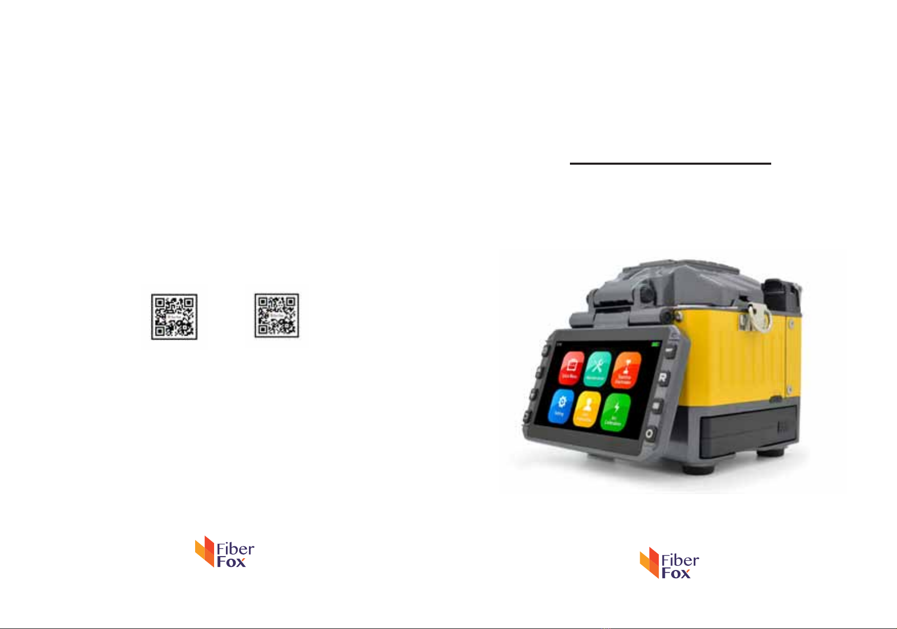
Mini 4S
User Manual
www.fiberfox.co.kr
www.fiberfox.co.kr
80, Dongseo-daero 179beon-gil,
yuseong-gu, Daejeon 305-320, Korea
website youtube

- 2 -
Contents
Introduction
Technical specifications
Splicer description & Part name
How to the replace the fiber folder
Cleaning
Splice Program
- Stabilize Electrodes
- Arc Calibration
- Splice Menu
- Maintenance
- Setting
1) Splice Mode
2) Splice Option
3) Heater Mode
4) Data Storage
5) Menu Lock
6) Reset
1) System Setting
2) Language
3) Power Save Option
4) Set Calendar
4
4
6
7
7
9
10
11
13
14
15
8
8
18
19
20
21
·
·
·
·
·
·

- 3 -
Appendix I
Appendix II
Appendix III
5) Password
6) System Information
26
28
31
23
24
·
·
·
Cautions
Important
The Battery must be taken out of the splicer, when stored in the Hand carrying case.
FiberFox highly recommend’s that all users read this manual before operating Mini 4S.
This manual is valid for the following software version.
- 4 -
Introduction
Technical specifications
Thank you for choosing Mini 4S FTTx Master from FiberFox. The Mini 4S with innovative design and
excellent manufacturing technology gives customers assurance of trust.
Exceptional splicing experience and new technology greatly reduces splicing and heating time.
Advanced estimate method and core alignment technique ensure the accuracy of the splice loss
estimation. Its small size, compact design and reliable protective casing make it suitable for any
operating environment. Dynamic operation interface and automatic splice mode give the custom-
ers great user-friendliness. For more information, please contact your local distributor or visit our
website at www.fiberfox.co.kr
This manual explains the features, specifications, operation, maintenance and warnings about Mini
4S. The primary goal of this manual is to make the user very familiar with the splicer operation.
Camera High precision dual camera
Display 4.3” wide color reinforced LCD
Microscope
x150 : X&Y axis dual view
x300 : X axis single view
x300 : Y axis single view
Power Supply
Splicer
AC 100~240V
50~60HZ
DC 9~14V
Li-ion Battery DC 11.1V
Data Capacity
Splice Mode
Factory pre-set 11 ea
User Mode 11 ea
Data Storage (Splicing result) 2,000
Max 10,000
Splice Speed
SM Quick mode 7 Sec.
SM AUTO mode 9 Sec.
- 5 -
Heater
Applicable Sleeve
Standard : 20, 25, 30, 35, 40, 60mm
Custom : 4*32mm sleeve (For SOC)
Heating Time 8~900sec (Typical: 15sec)
Heater mode
Factory pre-set 4 ea
User Mode 4 ea
Heating block
Standard 1 ea(Pre-installed)
SOC Customized 1 ea(In Package)
Applicable
Fiber
Fiber count : Single core
Fiber Type : SM(ITU-TG.652)/ DS(ITU-TG.653)/ NZDS(ITU-TG.655)/
ITU-TG.657 A,B Type / MM(ITU-TG.651)
Applicable
Cable
Fiber count : Single core fiber in cable
Applicable diameter : 0.25mm / 0.9mm / 2.0mm / 2.4mm / 3.0mm
Applicable buffer Diameter
: Cladding diameter : 80~150µm, Coating diameter : 100~3,000 µm
Splice Loss
SM : 0.03dB
MM : 0.01dB
DS : 0.05dB
NZDS : 0.05dB
G.657 : 0.03dB
Reliability
Operating
Condition
Altitude 0~5,000M
Humidity 0~95%
Temperature -15~60
℃
Wind Speed 15m/s
Storage
Condition
Humidity 0~95%
Temperature
Splicer -40~80
℃
Battery -20~30
℃
- 6 -
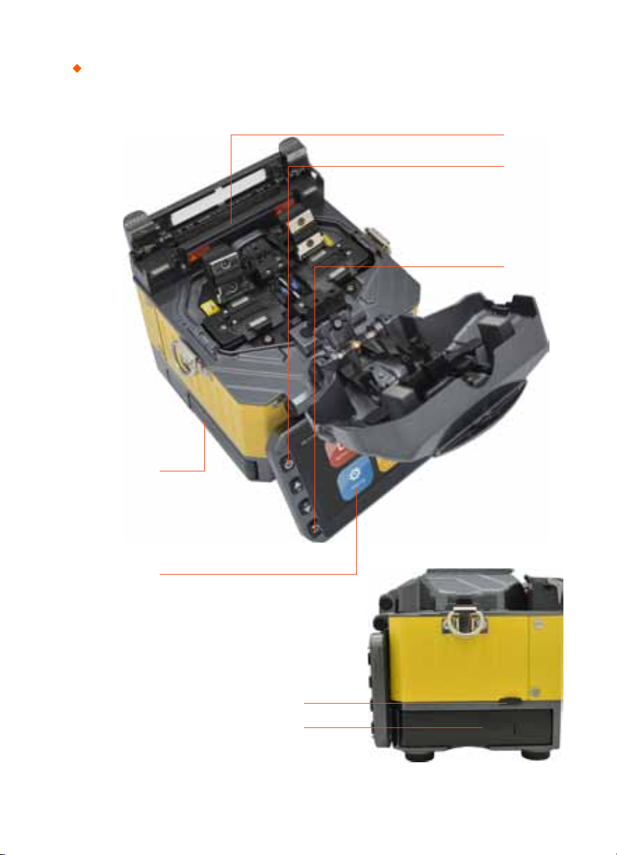
Splicer description & part name
Power Supply / Battery
Micro HDMI Port
Connenctor for Charging Battery
Return Button
ON/OFF Button
Sleeve Heater
Monitor
- 7 -
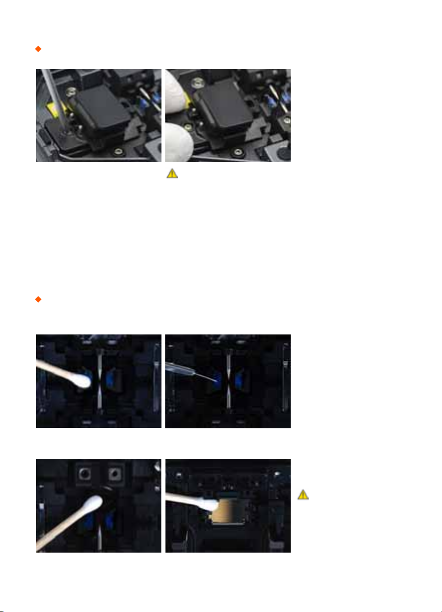
How to replace the fiber holder
Cleaning
1) Unscrew the screws
2) Take out the worn holder
3) Replace it with new one
4) Tighten up the screw
V-Grooves
Check fiber after cleaning
with cotton swab
1) Do not disturb
the electrode tips
2) Use only 99% or better
purity alcohol
Lens Mirrors
Caution
1) The unscrewd screws remain in the
holder (Do not remove the screws out)
2) Do not screw down the holder too tight
Caution

- 8 -
Splice Programs
Splice Menu, Maintenance, Stabilize Electrodes, Setting, User Instruction, Arc Calibration
Atmospheric conditions such as temperature, humidity, and pressure are constantly changing, which
creates variability in the arc temperature. This splicer is equipped with temperature and pressure
sensors that are used in a constant feedback monitoring control system to regulate the arc power
at a constant level. However, changes in arc power due to electrode wear and glass adhesion cannot
be automatically corrected. Also, the center position of arc discharge sometimes shifts to the left or
to the right. In this case, the fiber splicing position has to be shifted in relation to the arc discharge
center. It is necessary to perform an arc power calibration to eliminate these problems.
Note : Performing [Arc calibration] function changes the arc power “Factor” value. The factor value is
used in the algorithm program for all splicing. The arc power value will not change in the splice modes.
Standard Factor value is changed within 11 ± 2, It shows “Complete” word.
[Arc Calibration]
In the event of sudden change in environmental conditions or after cleaning electrodes, the arc power
sometimes becomes unstable, resulting in higher splice loss. This is especially a concern when the
splicer is moved from lower altitudes to higher , it takes time for the arc power to stabilize. In this case,
stabilizing electrodes will expedite the process to normalize the arc power. If many tests are required
to get the “Test ok” message appearing the [Arc calibration], use this function as well.
[Stabilize Electrodes]
*

- 9 -
1) Splice Mode
[Splice Menu]
Factory Pre-Set Mode 11 ea
User Mode User Edit : 11ea
Customized mode : 1 ea
Delete Splice Mode -

- 10 -
2) Splice Option
Auto Start
ON : Automatic splicing procedure
OFF : Maunal Splicing procedure
Pause 1
(Press Motor)
ON : Pause after the fiber gap position process
OFF : Proceeding without the pause
Pause 2
(Align Motor)
ON : Pause after camera focus & Axis alignment process
OFF : Proceeding without the pause
Realign After Pause 2
ON : Automatically proceed realignment
OFF : Proceeding without the pause
Ignore Splicing Error ‘splicing error’ message is not displayed
Fiber Image On Screen Select display structure for each splicing process
- 11 -
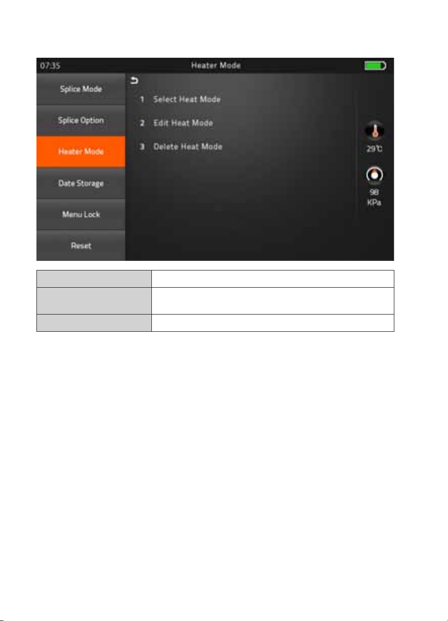
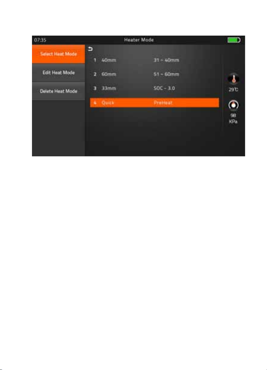
3) Heater Mode
Factory Pre-Set Mode 4 ea
User Mode User Edit : 4ea
Customized mode : 1 ea
Delete Heater Mode -
- 12 -
▶
Preheat Mode
It is performed for reducing heating time and rapid heating task. When it comes to turned
on program, red LED keeps blinking which means it is warming up the heater about 120 to
160
℃
itself. After a few minutes, it is avaiable to shrink the sleeve in 15 seconds (Refer to
60mm sleeve which used to perform in 20 seconds)
However, Please be attention, it wastes more the battery power than Normal heating
mode. (Normal Cycle is approximately 400, whereas, it performs 295 cycle)

- 13 -
4) Data Storage
Display Splice Record Displaying your detailed splice record
Delete Splice Record -
Export Splice Data Downloading saved data (Splice record or Image)
User Information Record the work information into the data save file
Splice Data Save
ON : Automatic data save
* Image data is saved manually *
OFF : Do not save splice record

- 14 -
5) Menu Lock
Input password to access the sub-menu
Splice Mode Lock
ON : Disable ‘Splice mode’ edit
OFF : Ensable ‘Splice mode’ edit
Heater Mode Lock
ON : Disable ‘Heater mode’ edit
OFF : Enable ‘Heater mode’ edit
Recordes Delete Lock
ON : Disable ‘Record mode’ edit
OFF : Enable ‘Heater mode’ edit
Password Lock
ON : Disable to change the password
OFF : Enable to change the password
- 15 -
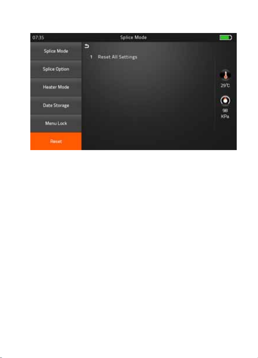
6) Reset
Unexpecting the malfunction occurred on splicer, it is necessary to make all the param-
eter to be the factory set mode. However, It is highly recommended to execute task after
discussed with a fiberfox technician. Whereas lower 1.34 version is necessary to execute
Reset to adapt new function of program on splicer after upgrading process.
- 16 -
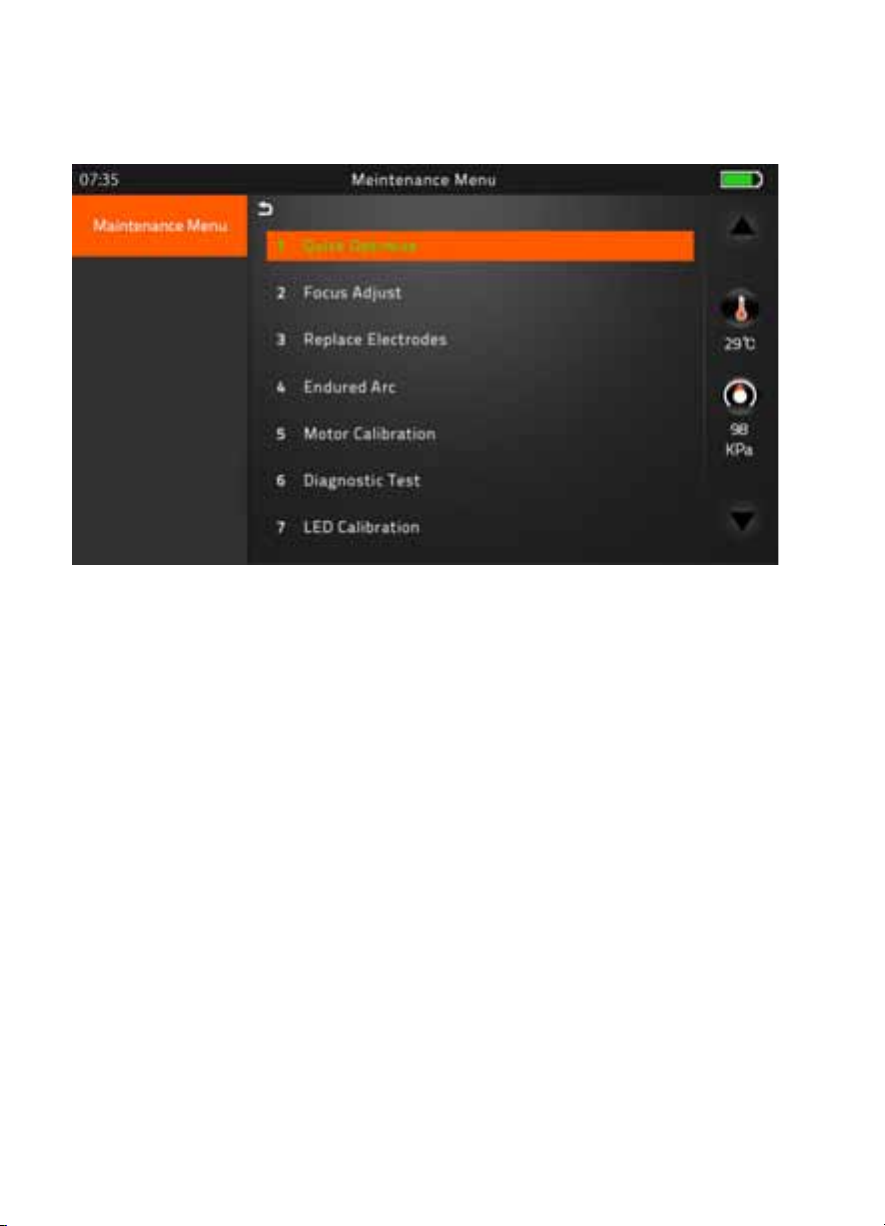
1) Maintenance Menu
▶ Quick Optimize
Quick & Easy overall maintenance
Automatic process ‘Lens focus+motor calibration+fiber training’
▶ Focus Adjust
Find the optimized position for ‘Focus Motor’
▶ Replace Electrodes
Instruction on how to replace electrodes
FiberFox recommendation
It is highly recommended to change the electrodes after every 3,000 splicing
* After finished to use this menu, the current Arc Count would be reset to ‘0’
▶Endured Arc
Training for new electrodes adjustment
It occurs 30 times arc training for adjusting new electrodes function.
It is recommended to try on completion. Replace Electrodes menu.
▶ Motor Calibration
Automatically calibrates the speed of all six motors
[Maintenance]
- 17 -
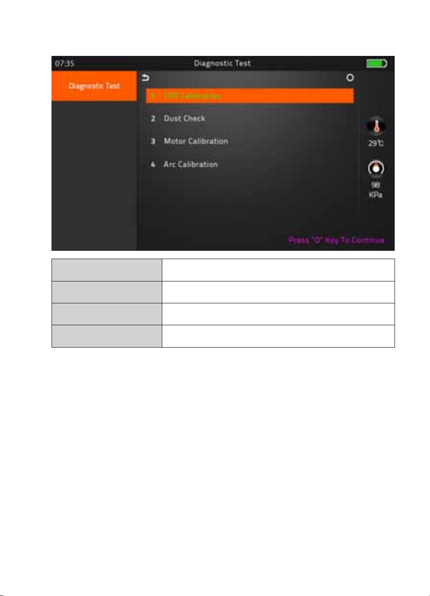
▶ Diagnostic Test
LED Calibration Measures and adjusts the brightness of LED
Dust Check Dust checking process
Motor Calibration Automatically calibrates the motor speed
Arc Calibration Automatically calibrates the Arc power
▶ LED Calibration
Measures and adjusts the brightness of LED
▶ Dust Check
Detects dust&contaminant causing improper splicing
In order to find out optimized position for splicing, the splicer analyses the fiber images being
transmitted by the optical camera & LED inside but dust or contaminant on the camera, lenses,
LED may cause inaccurate splicing results.
Therefore, the dust check process is recommended to proceed in case of frequent splicing fail
or high insertion loss.
- 18 -
Automatic Fiber recognition program
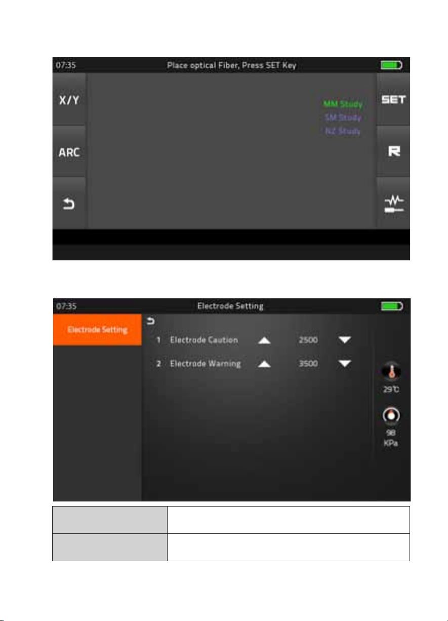
▶ Electrode Setting
▶ Fiber Training
Electrode Caution Caution alram will be displayed when it reachs the number of
splicing cycle you set
Electrode Warning Caution alram will be displayed when it reachs the number of
splicing cycle you set

- 19 -
▶ Motor Drive
This checks the operation status of motors.
* Method : Chosen one of motor by Tapping in middle of motor name, And move to press up and
down arrow keys
▶ Update Software
Upgrade to the latest software version.
Procedure
1Prepare the USB device.
2Download the latest version software to the USB.
3Link to the Splicer (Via link cable in the package).
4Press “O’ Button to proceed update.
5Device will be rebooted once it is done.
6Splice Menu > Reset (Format) > Input Password > Execute Format task
7Execute the Quick Optimize > Stabilize Electrodes > Arc Calibration
- 20 -
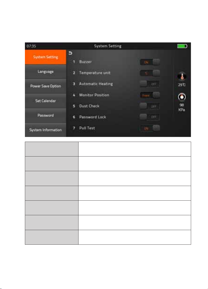
[Setting]
1) System Setting
Buzzer ON : Sound on
OFF : Sound off
Temperature Unit
℃
: Celcisius
℉
: Fahrenheit
Automatic Heating ON : Auto start
OFF : Manual start
Monitor Position Front : Normal direction display
Rear : Opposite direction display
Dust Check ON : Check the dust density
OFF : Skip dust checking process
Password Lock ON : Password is required to operate the device
OFF : No passwerd is required
Pull Test ON : Automatic pull test processing after splicing
OFF : Skip pull test process
This manual suits for next models
4
Table of contents
Other FIBER FOX Welding System manuals


Popular Welding System manuals by other brands


Lincoln Electric
Lincoln Electric FlexCut 200 Operator's manual

Miller Electric
Miller Electric MT-26 Torches owner's manual

KOLARC
KOLARC MX350 owner's manual

Cebora
Cebora Synstar Twin 270 T instruction manual

ESAB
ESAB Precision Plasmarc IEFC-S PT-24 Installation, operation and maintanance manual

Northen Industrial Welders
Northen Industrial Welders MIG 135 Quick setup guide