Briteq VP-P37.5 Manual

VP-P37.5 preliminary setup instructions
Mechanical screen assembly
- Put the screen together using the quick lock adapters
o Always fix the “VP-P37.5 BRACKET” first: suspended to the ceiling or truss construction.
Make sure that the ceiling/truss construction can support the complete screen!
Each bracket can support a column of up to 10 panels. (screen height = 6m)
o Fix the panels in rows: first install 2 rows before you start lock the upper row. This makes it
easier to build the screen together.
Electrical screen assembly
Please refer to the drawing:
The drawing shows the screen from the BACKSIDE! This means that you should place yourself on
the backside of the screen and follow the instructions below:
- Data (video signal) is cabled horizontally: always from left to right, starting from the top row!
o The VP-SCANBOX has 8 outputs:
Output 1 is connected to the most left panel of the upper row. (panel1 on the drawing)
Output 2 is connected to the most left panel of the 2nd row. (panel8 on the drawing)
o If the screen is too big for 1 scan box, you can easily connect several scan boxes together,
using the RJ45 in/out connectors and the (blue) CAT6-cable. Configuration of the setup is
done in the setup software.
o Use the small 30cm data cables to daisy chain panels in a row.
Note: VP-SCANBOX supports theoretically up to 12panels (192pixels) per output but to have
good performance you should limit this number to max. 8 panels per output. (ideal = 5 to 6
panels)
- Power (230Vac) is cabled vertically: always from bottom to top.
o Use the small 30cm power cables to daisy chain panels in a column.
Note: a special power cable (VP-POWERLINE 4/30P) is available: it has a length of 4m and
has 4 outputs so you can connect 4 colums and up to 30 panels.
Interface assembly
You need a Windows PC (or laptop) + “VP-PC INTERFACE” + one or more “VP-SCANBOX” to setup
the interface with the screen.
- PC VP-PC INTERFACE:
2 lines are needed:
o USB line: use the supplied USB-cable. Important! Before you connect the VP-PC
INTERFACE to your PC, you should install the USB-drivers! (see attached file with drivers)

o DVI line: if your PC has an HDMI output, you can buy a simple HDMI/DVI conversion cable. If
your PC only has VGA output, you will need a USB/DVI-converter. In fact this is an external
video card which converts USB signals to DVI. (possible supplier: www.manhattan-
products.com “hi-speed USB2.0 to DVI converter”)
- VP-PC INTERFACE VP-SCANBOX:
1 CAT6-cable can be connected between the U-sender output of the VP-PC INTERFACE and the
RJ45 input of the VP-SCANBOX. This cable can reach a length up to 100m.
Software setup
- Insert the CDROM: a window pops up choose “installing
LED play software”
- Select ENGLISH as installation language
- Registration information:
o Name: put your name
o Company: put the name of the venue or your company.
o Serial: just put key in 888888
- Press the “next” button software will be installed.
- Start LED STUDIO program
- Open the OPTION menu and select “Software setup” a
new window opens.
- Put the cursor (Windows arrow) somewhere in this new
window (but NOT in a data input filed!) and press linsn (you
will hear some noises while typing this word) a password
window opens.
- Please insert the password 168 and press the OK button.
- In the new window (setup hardware
parameters): choose the option
“RECEIVER” on the top.
- On the bottom press the button
“LOAD FROM FILES” and load the
file “p37.5R.RCG” (configuration file,
supplied with the screen) on the
upper right of the window you will
see the name of the file appearing.
(see picture on the right)
- Just below, please change the option
“gray level” to “Hi-brightness 512” (or
Hi-brightness 256”)
- On the second part of the window

you will see “Load capacity setup” here you should tell the software the exact height + width of
the complete screen in pixels!!!
- One P37.5 panel measures 16x16 pixels so for our example screen you will have the following
data:
o Width: 7panels x 16 pixels = 7 x 16 = 112pixels fill in “112” for width
o Height: 5panels x 16 pixels = 5 x 16 = 80pixels fill in “80” for height
Fill in the exact data for your screen and press the button “SEND TO RECEIVER”: in the new
window select ALL and press OK.
When everything works well, you still have to save the settings permanently to the scan box.
To do this, press the “SAVE TO RECEIVER” button: in the new window select ALL and press
OK.
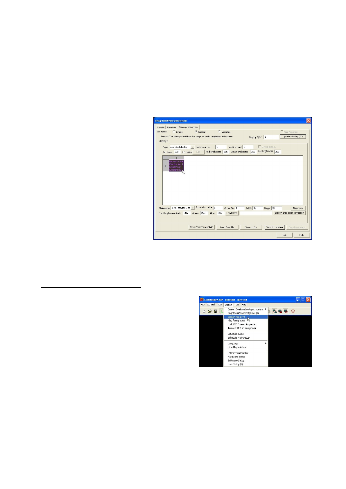
- Now in the window (setup hardware
parameters): choose the option
“DISPLAY CONNECTION” on the
top. the window on the right
appears.
- When only 1 VP-SCANBOX is used,
make sure that “Horizontal card” is
set to 1 and also “Vertical card” is
set to 1. One pink box
(representing the scan box)
appears.
- Press the pink box until it turns grey
and you are able to configure it on
the bottom of the window, fill in:
o Main cable: 1 No sender U
o Extension cable: 1
o Order No: 1
o Width: width of the screen in
pixels (example: 112)
o Height: heigth of the screen in pixels (example: 80)
- Press “SEND TO RECEIVER” button to send the data to screen.
- When everything works well, you still have to save the settings permanently to the scan box. To
do this, press the “SAVE TO RECEIVER” button
- Press EXIT button until come back to the main screen of the program.
Location of the screen capture area:
The screen works simply by sending the contents (copy) of a portion of your PC-screen to the video
screen. So the output of any program you drag in this area
will be shown on the screen. Of course you need to know
which part of the screen is copied to the screen. To make
this part visible, do the following:
- Open the Option screen and select “Screen area (Y)”
a small part of the screen is marked by a red
square. All windows dragged inside this square will be
copied to the video screen.
- On the bottom of this window you can choose to put
the square permanently on the screen: easy to find
the captured screen area.
Please note that this is a first draft which is not finished yet,
we apologize for any inconvenience caused.
Table of contents