HELVAR SCENESET HES91010 User manual
page 1
Document Ref. EPD05113 (08/04/98) ENGLISH Part No. I259GB issue 5
INTRODUCTION
These instructions relate to the installation, basic connection and
setting-up of an HES91010 SCENESET Lighting Controller.
For operational instructions, please refer to the User Guide
(part no. I299GB) supplied separately.
INSTALLATION
Choosing a Suitable Location
The HES91010 is designed to be mounted vertically with the connection
points at the bottom; this is to ensure correct ventilation.
The chosen mounting surface must be flat and the location must meet the
following requirements:
·A clearance of at least 100mm on all sides is recommended to allow
for adequate ventilation.
·Sufficient clearance must be left below the unit to allow for the
connection of cables, conduits or trunking.
·The ambient temperature must be within the range 0C to 35C and the
area must be adequately ventilated.
·Humidity should be within the range of 0 to 90% (non-condensing).
DO NOT install this product in a damp location.
Fixing Method
Mounting is achieved by using the four ‘keyhole’ fixing holes on the side
flanges. The fixing screws (not supplied) must be chosen to suit the
following criteria:
·Wall Construction – suitable wall plugs must be used for masonry
construction and plasterboard partitions.
·Screw Length – must be sufficient to securely anchor the unit.
·Screw Head - round-head, pan-head or cheese-head screws must be
used. The head size should be small enough to just pass through the
large area at the centre of the fixing hole and large enough to clamp
the flange securely in the slotted portion of the hole.
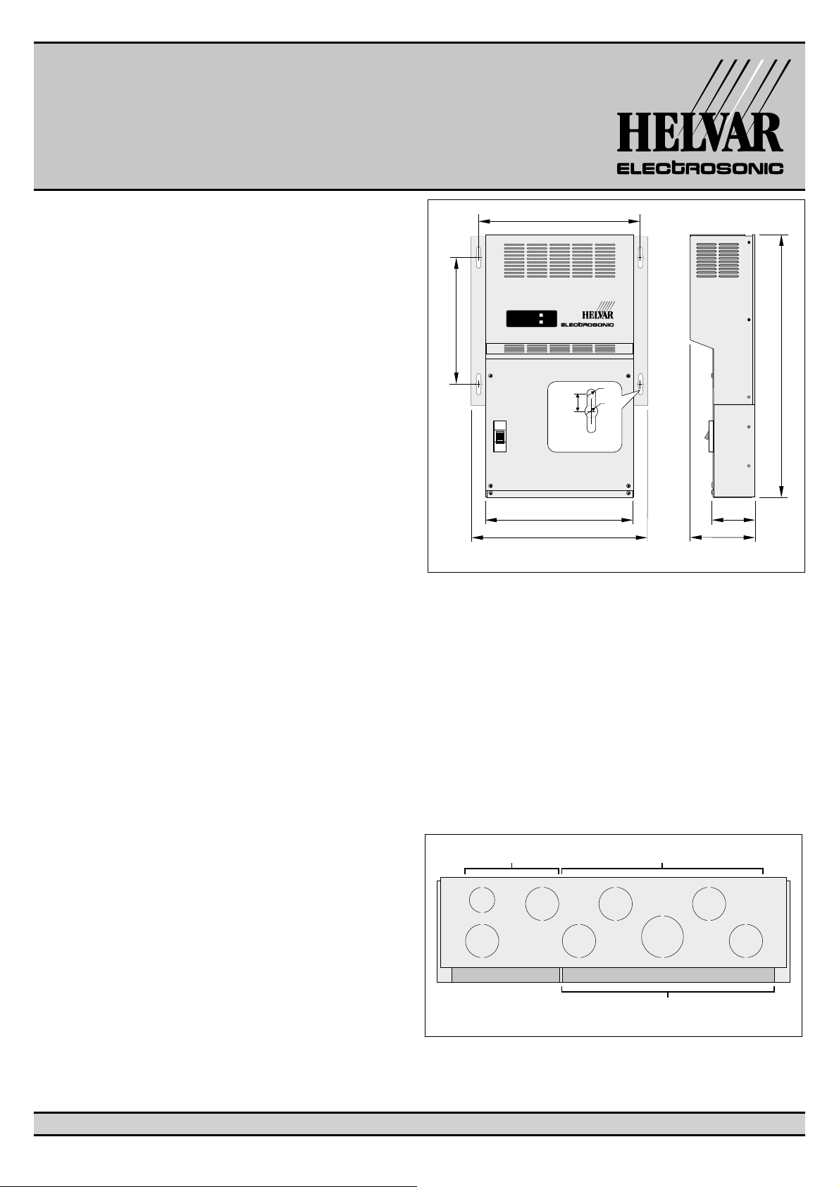
1. Mark and drill four holes to correspond with the centres of the
fixing holes (see Fig.1-1), and fit wall plugs as required. Note the
drop-down clearance of 12mm.
2. Insert the screws, and screw them in until the distance between the
wall and the underside if the screw heads is a little more than the
depth of the flange.
3. Align the centres of the flange fixing holes with the screws, then
allow
the slotted part of the holes to drop-down behind the screw heads.
If necessary, loosen the screws to ease this operation.
4. Finally, tighten all four screws sufficiently to prevent the unit from
being lifted away.
211
230
181
370
251 93
63
(ALL DIMENSIONS IN mm.)
HES91010 SCENESET – LIGHTING CONTROLLER
Ø5.0
KEYHOLE SLOTS
(4 off) for securing the unit
Ø8.0
Drop Height
= 12mm
Fig.1-1: Overall dimensions & fixing holes positions.
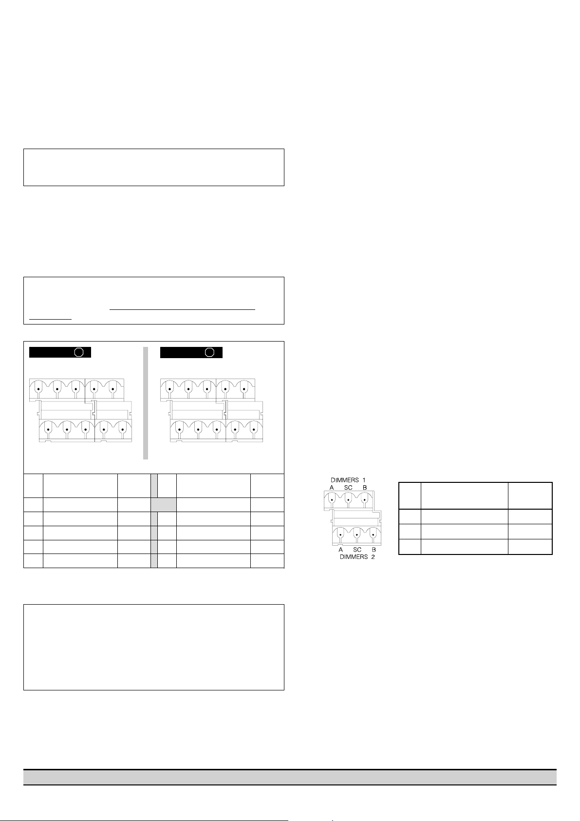
Cable Access
There are various ‘knock-outs’ on the base of the unit which are suitable
for 15, 20, or 25mm conduit fixings (see Fig.1-2).
These are arranged such that the three left hand positions are used
exclusively for mains cables, whilst the remainder are used for the FELV
(Functional Extra-Low Voltage) control connections.
If required, control cables which are not in conduits can enter the unit via
the slot behind the knock-outs.
MAINS CABLES LOW VOLTAGE CONTROL CABLES
Entry point for free cables
(not in conduit)
15
20
20
20 25
20 20
20
Fig.1-2: Cable entry knock-outs
Installation Instructions
SCENESET™Lighting Controller
HES91010
Document Ref. EPD05113 (22/07/03) ENGLISH Part No. I259GB issue 6

Document Ref. EPD05113 (22/07/03) ENGLISH Part No. I259GB issue 6
page 2
MAINS SUPPLY INPUT
Voltage Range
The SCENESET Lighting Controller is factory-set for use with one of the
following voltage ranges which cannot be changed by the user:
·230V a.c. (nominal); 180V – 260V a.c. (absolute).
·115V a.c. (nominal); 90V – 130V a.c. (absolute).
Check that the controller is set for the correct range for the intended power
supply by referring to the serial no./rating plate which is mounted inside
the control connection compartment (behind the right-hand access plate).
WARNING: THE MAINS INPUT MUST BE CONNECTED TO A
SINGLE-PHASE SUPPLY ONLY AND MUST BE EARTHED.
CAUTION:Connecting a supply which exceeds the maximum voltage for the
appropriate input range may cause irreparable damage to the SCENESET.
Frequency Range
The input supply frequency should be within the range 45 – 65Hz.
Supply Protection
The supply input is protected by the internal 3A MCB. No further
external supply protection is required.
Connecting the Mains Supply
Access to the mains input terminals is gained by removing the access
plate (four-screw fixing).
Cable Function Connection Point
Live Input Bottom screw terminal of the MCB
Neutral Cream coloured screw-terminal block.
Earth Green/Yellow coloured screw-terminal block.
Suitable cable type: Solid, stranded or flexible.
Cable size: 1.5mm2– 4.0mm2.
Stripping length: 12mm (for MCB)
10mm (for other terminals).
EARTH
NEUTRAL
LIVE
Fig.1-3: Mains connection terminals
BREAKOUT MODULE
The BREAKOUT module is located behind the access plate (on the
right-hand side) and provides connection points to the various FELV
(Functional Extra-Low Voltage) data and control circuits (see Fig.1-4.).
·S-COM (external) power & data highway.
·S-COM (star) data highway.
·S-COM (internal) data highway.
·S-DIM data highways.
·SCENESET watchdog relay contacts.
·BREAKOUT module relay coil and contacts.
·DIMMER level override input.
These allow the connection of various external control input or output
devices and enable separate SCENESETs to be linked. Full details of each
connector and its function are given in the User Guide.
Suitable Cable
All of the S-COM and S-DIM data highways require a screened twisted
pair, whilst all other connections should use equipment wire. For full
details, refer to the Electrosonic Control Cable Specifications data sheet
(part no. I237GB).
Special S-COM cable is available from Helvar Electrosonic which
comprises the following conductors in an overall sleeve:
·Twisted pair with screen (for data lines).
·Two power wires (for S-COM supply).
This is ideally suited for use with the S-COM (external) line, but may also
be used on the other S-COM and S-DIM lines if the two power wires are
cut back.
Configuration Switches
A bank of eight DIL slide switches is provided on the module which are
used for the following purposes (from left to right):
·Switches1–3 Toselect different interconnections of the
SCENESET watchdog and DIMMER override circuits.
·Switches4–8 Toselect line termination on the various
data highways .
All of the configuration switches are factory-set to the ‘ON’ (up) position,
but these can be changed if required.
1
23
456
78
LEVEL RELAY SCENESET DIMMERS 1 STAR PANEL
CN1
LK1
CN10
OFF
CONFIGURATION
SWITCHES
TEMP WATCHDOG SCENESET DIMMERS 2 RELAY PA NE L
Fig.1-4: Location of BREAKOUT Module.
Document Ref. EPD05113 (22/07/03) ENGLISH Part No. I259GB issue 6
page 3
S-COM Loading
Each device that can be connected to the S-COM (external) data highway
has a Unit Loading Factor (ULF) according to its power consumption.
The total of the ULF’s for all devices connected must not exceed 15:
SCENECOMMANDER:1
SCENETIMER:1
INPUT module: 1 (using bistable inputs & LCS only).
1.5 (using LCS, analogue & bistable inputs).
LCS panels: 0.25 (via INPUT module only).
LCS infra-red unit: 0.5 (via INPUT module only).
CHANNEL COMMANDER:1
STAR DISTRIBUTION unit: 2.
The S-COM (external) line also has the capacity to support either
SCENEMAKER or SCENEPLANNER without affecting the total number of
devices permitted.
Line Termination
If the BREAKOUT module is located at one end of the data highway, set
switch 4 (‘PANEL’) to the ‘ON’ (up) position.
If the module is located along the highway, set switch 4 to ‘OFF’.
S-DIM
Two data highways are available (S-DIM #1 and S-DIM #2) which can be
used to connect various output devices (e.g. DIMMER modules, OUTPUT
modules, etc.).
Connection Details
Connection to each S-DIM highway is made via the 3-way connectors
labelled ‘DIMMERS 1’ and ‘DIMMERS 2’ (Fig.1-5). Both S-DIM highways
are functionally identical but are electrically buffered. If the BREAKOUT
module is located along either data highway, both halves of the highway
need to share the same connector.
Mating connector part no.: P9830 (3-way).
Cable size: 0.2 – 2.5mm2.
Stripping length: 7.0mm.
S-DIM Loading
Each highway can support up to 64 channels (e.g. 16 x HES99400). Thus a
total of 128 channels can be controlled when using both highways.
Line Termination
If the BREAKOUT module is located at one end of the data highway(s), or
if the connections are not used, set switch 7 (‘DIM 1’) or switch 8 (‘DIM 2’)
to the ‘ON’ position accordingly.
If the module is located at some point along the highway(s), set switches
7or8tothe‘
OFF’ position.
S-COM (external)
This data highway is used to connect the following scene-recall devices:
·SCENECOMMANDERs.
·SCENETIMER.
·INPUT Module.
·CHANNEL COMMANDER
·STAR DISTRIBUTION Unit [also requires S-COM (star) line].
Connection Details
CAUTION
Ensure that the SCENESET controller is turned-off before attempting to
connect the S-COM (external) highway.
Connection of the S-COM (external) highway is made via the 5-way
connectors labelled ‘PANEL’ (Fig.1-6). Both connectors are electrically
identical. If the BREAKOUT module is located along the data highway,
one connector should be used for each half of the highway.
Mating connector part no.: P9850 (5-way).
Cable size: 0.2 – 2.5mm2.
Stripping length: 7.0mm.
CAUTION
Please note that the power supply connections are different on issue Cand D
BREAKOUT Modules — check for correct polarity before powering the
S-COM line.
CAUTION
Incorrect connections may result in damage to the internal circuitry of the
controller and of any other devices connected to the S-COM (external)
highway.
Check that all connections are correct and that there are no short-circuits
before powering-up the SCENESET controller. In particular, ensure that the
data lines are not accidentally or deliberately connected to the supply lines.
Fig.1-5: Connection details for S-DIM#1 & S-DIM#2.
Pin Function Wire
Colour
A S-DIM data A Red
SC Power ground (0V) —
B S-DIM data B Black
B
B
+
+
–
–
A
A
SC
SC
PANEL
PANEL
B
B
–
–
+
+
A
A
SC
SC
PANEL
PANEL
PCB Issue :C
PCB Issue :C
PCB Issue :D
PCB Issue :D
Fig.1-6: Connection details for S-COM (external).
Pin Function Wire
Colour Pin Function Wire
Colour
– Power ground (0V) Grey Power supply (40V) Purple
A S-COM data A Red A S-COM data A Red
SC Screen (earth) — SC Screen (earth) —
B S-COM data B Black B S-COM data B Black
Power supply (40V) Purple – Power ground (0V) Grey
page 4
WATCHDOG/LEVEL OVERRIDE
The SCENESET watchdog and DIMMER level override circuits are
provided to allow the DIMMER outputs to be taken to a pre-defined level
if the SCENESET controller loses control (automatic watchdog). This level
override facility can also be triggered by a separate security/fire alarm
system.
These two circuits, together with a relay on the BREAKOUT module can be
interconnected by using switches 1,2&3;forfull details of other circuit
applications, refer to the User Guide. Note that although switches2&3
are separate, they are always operated as a pair (i.e. both ‘on’ or both
‘off’).
Selecting Automatic Watchdog (Switches 1,2&3)
These are factory-set to the ‘ON’ position but may be changed as
required.
With all three switches set to the ‘ON’ position (default), automatic
watchdog is enabled; with all three switches set to the ‘OFF’ position,
automatic watchdog is disabled.
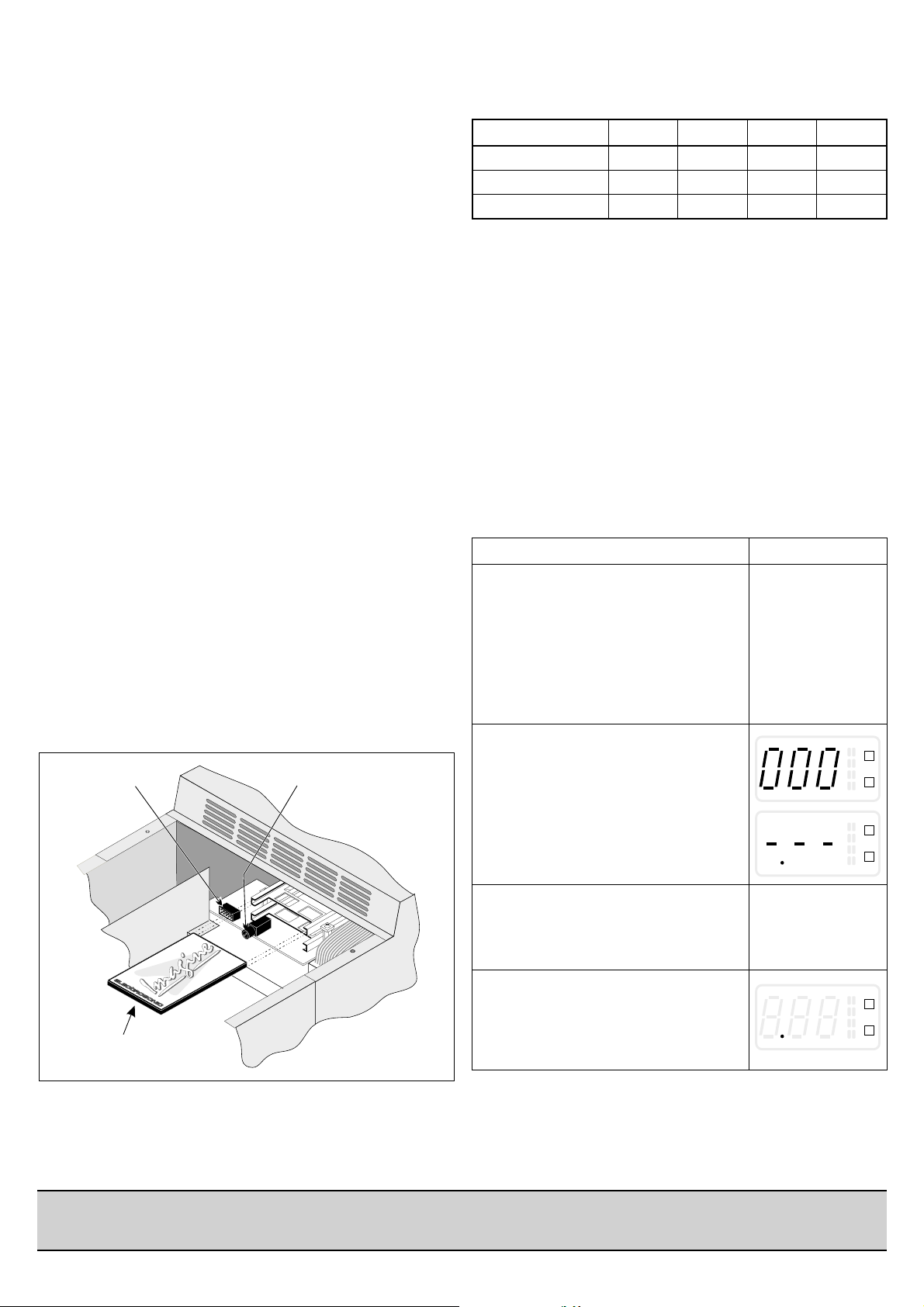
SCENESOFT CARDS
There are two slots behind the access plate (on the right-hand side)
which are used for SCENESOFT memory cards (see Fig.1-7):
The card in slot ‘A’ (which is nearest the front panel) is used by the
SCENESET controller to retrieve and store the following data:
·SCENESET address.
·DIMMER output levels for each scene.
·DIMMER parameters.
·Scene parameters (linking, fade times, re-directions, etc.).
ASCENESOFT card must be plugged into slot ‘A’ to allow the SCENESET
to function correctly. The card can either be pre-programmed or
programmed in situ by connecting a SCENEMAKER or SCENEVIEWEDITOR
to the Programming Connector.
Slot ‘B’ is used in conjunction with the SCENESET‘s ‘Copy’ function to make
a copy of the card in Slot ‘A’ (see the User Guide for further details).
Card Capacity
The number of scenes stored on the card depends on its capacity. Three
types of card are available offering different system capabilities:
Card Type/Capacity Scenes Triggers Redirects Clusters
HES90120 8K 40 10 10 2
HES90240 128K 600 150 150 15
HES91280 512K 1024 500 500 50
Choose the card type carefully to match current requirements, and also
allow for any anticipated future expansion.
Default Scene
The SCENESOFT card can be programmed to perform one of two actions
when the SCENESET controller is powered-up:
·Default to scene zero (‘000’).
·Restore the last known output levels (‘000’ is displayed but any
programmed levels for scene zero are ignored).
NOTE Whilst scene zero can be programmed in the same way as any other,
it cannot be recalled via the S-COM line (except with
SCENEPLANNER).
POWER-UP PROCEDURE
Procedure Display & Buttons
1. Remove the access plate and insert a
programmed SCENESOFT card into slot ‘A’
(nearest the front) and turn-on the mains
supply.
Note: Ensure that the card is correctly
orientated i.e. with the logo side facing
outwards and with the ‘arrowhead’ symbol
pointing towards the slot.
(see Fig.1-7)
2. After approximately one second, the
display should change to show scene zero.
If the display shows three dashes, this
indicates that the card cannot be read. This
may be caused by an unformatted card, or
if the card’s internal battery is discharged
or missing.(Refer to the User Guide).
3. The SCENESET will now perform a
‘logging-on’ process of all the devices
connected to it. This may take up to 30
seconds in a large system, during which
time the display will not change.
4. If the diagnostic flag indicator is lit
(between the first two digits), one or more
diagnostic codes are waiting to be
displayed.
Refer to the User Guide for details.
Programming
Connector
S-COM Supply
Fuse Holder
scenesoft
SceneSoft Card
(inserted into slot A)
Fig.1-7: Card slots, program connector & fuse holder.
© 1997 HELVAR ELECTROSONIC Group Part No. I259GB
Hawley Mill, Hawley Road, Dartford, Kent. DA2 7SY (U.K.) Document Ref. EPD05113
Tel: 01322 222211 Fax: 01322 282282 issue 6 (22/07/03)
Table of contents
Other HELVAR Recording Equipment manuals


