Broadcast Concepts Inc
11700 NW 102nd Road Suite 4Medley FL 33178
Tel: 305.887.8400 FAX 305.887.8444
Broadcast Concepts Inc
Revised 8/20/2014 3
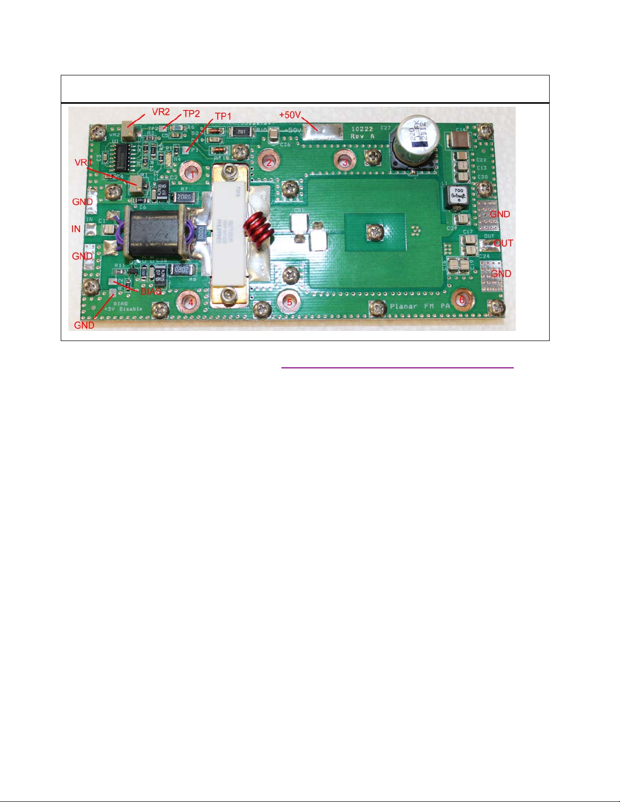
Electrical Notes:
There is 1 +50V pad for the main power supply. The Meanwell RSP1500 is the suggested power supply
for this amplifier. Do not attempt to connect ground to the pallet or modify the PCB for ground
attachment. Ground can be attached to the heat sink that the pallet is mounted on.
The pot VR1 marked “Bias” controls the bias current for BLF188XR. The factory setting is 100ma and
adjustment is not required.
The adjustment pot VR2 marked sets up the thermal compensation slope. Adjustment of this pot is not
required; however, if it is accidently tampered with simply re-adjust it until “7.2 volts” is present at TP1 as
this is the factory setting. “Bias disable” removes bias voltage from the transistor. A voltage above 2.0V is
required to activate the “bias disable” condition.
If coax cables are being soldered to the module use Teflon cables MIL-C-17 rated only. Do not use a coax
larger than RG402 on the output. Attempting to solder large coax cables like LMR400 directly to the PCB
may damage the pallet and render it beyond economical repair. The best cable for the output is 0.141 inch
conformable 50 ohm type.
If transistor replacement is necessary always verify that the bias circuits are functioning before installing
new parts. Transistor pocket must be cleaned with alcohol, all debris removed and new thermal compound
applied prior to installing new transistor. Bias voltage should be adjusted to 0.5V before new part is
installed. We assume no responsibility for self repairs. Please consider sending pallet back to factory for
service.
When bias adjustment is required always use a small lab supply that is current limited. This will prevent
accidental over bias and loss of a transistor.
Warning: Solid state amplifiers can be easily destroyed! Operating the amplifier outside of its
specifications will cause the mosfets to fail. These failures are not covered by warranty.
•Do not over drive the amplifier.
•Do not run the amplifier into an open circuit. Do not run the amplifier when the SWR is unknown.
System integrator must foresee adding VSWR protection if there is a risk that the amplifier will be
subjected to high VSWR conditions. Do not adjust the bias settings or attempt transistor
replacement without a current limited lab supply.
•Do not allow the amplifier to overheat. Do not let the base plate temp exceed 70C. This amplifier
is capable of dissipating over 350W in the maximum working condition. This product requires
prior experience working with high power RF amplifiers. This is not for beginners.
•This amplifier has been designed for analog FM broadcast. Performance in digital FM has not been
evaluated.
•Expensive test equipment like RF wattmeters, dummy loads, Ammeters and thermal meters are
required to verify proper installation. Operating this amplifier without this equipment is like