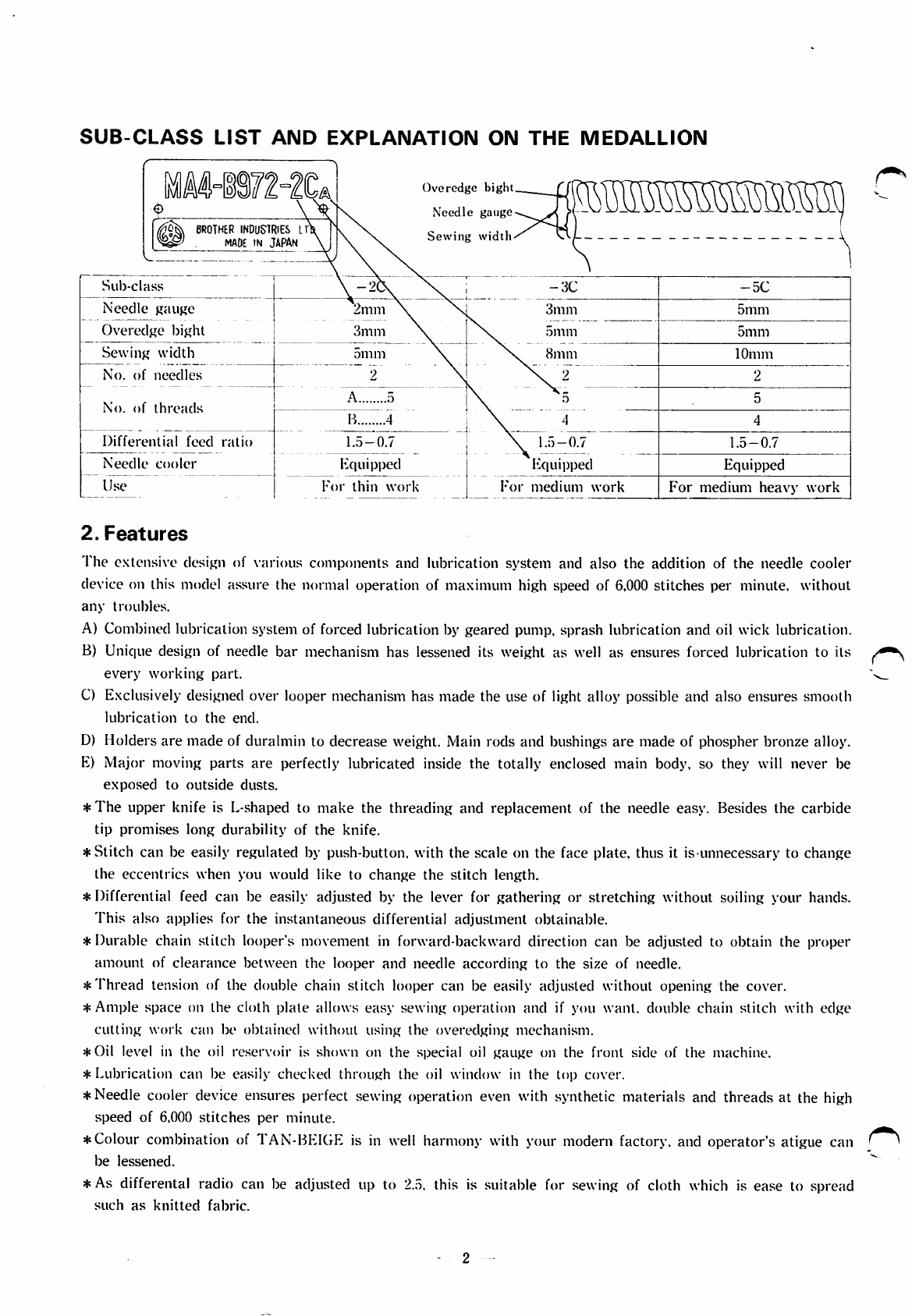
SUB-CLASS
LIST
AND
EXPLANATION
ON
THE
MEDALLION
BROTHER
INDUSTRIES
IT
MADE
IN
JAPAN
Overedge
biglu
Needle
gauge
Sewing
width
Sub-class
\
-2\
\
-3C
—
5C
Needle
gauge
2mm
\
3mm
5mm
Overedge
bight
3mm
\N.
5min
5mm
Sewing
width
5mm
\N.
8mm
10mm
No.
of
needles
2 \ \ 2 2
No.
of
threads
A 5 \5
B 4 \4
Differential
feed
ratio
1.5-0.7
\
1.5-0.7
1.5-0.7
Needle
cooler
Equipped
Equipped
Equipped
Use
For
thin
work
For
medium
work
P'or
medium
heavy
work
2.
Features
The
extensive design of various components and lubrication system and also the addition of the needle cooler
device
on
this
model
assure
the
normal
operation
of
maximum
high
speed
of 6,000
stitches
per
minute,
without
any
troubles.
A) Combined lubrication system of forced lubrication by geared pump, sprash lubrication and oil wick lubrication.
B) Unique design of needle
bar
mechanism
has
lessened its weight as well as ensures forced lubrication to its
every
working
part.
C) Exclusively designed over looper mechanism has made the use of light alloy possible and also ensures smooth
lubrication
to
the
end.
D) Holders
are
made
of duralmin to decrease weight. Main rods and bushings
are
made of phospher bronze alloy.
E)
Major
moving
parts
are
perfectly lubricated inside the totally enclosed main body, so they will never be
exposed
to
outside
dusts.
*The
upper knife is L-shaped to
make
the threading and replacement of the needle easy. Besides the carbide
tip
promises
long
durability
of
the
knife.
*Stitch can be easily regulated by push-button, with the scale on the face plate, thus it is unnecessary to change
the
eccentrics
when you would
like
to
change
the
stitch
length.
*Differential feed can be easily adjusted by the lever for gathering or stretching without soiling your hands.
This
also
applies
for
the
instantaneous
differential
adjustment
obtainable.
*Durable chain stitch looper's movement in forward-backward direction can be adjusted to obtain the proper
amount
of
clearance
between
the
looper
and
needle
according
to
the
size
of needle.
*
Thread
tension of the double chain
stitch
looper can be easily adjusted without opening the cover.
*
Ample
space
on
the
cloth
plate
allows
easy
sewing
operation
and
if you
want,
double
chain
stitch
with
edge
cutting
work
can
be
obtained
without
using
the
overedging
mechanism.
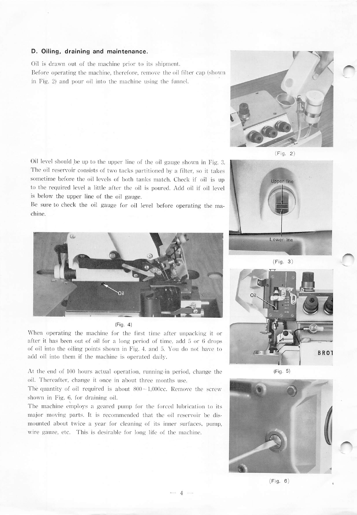
*Oil
level in
the
oil
reservoir
is
shown
on
the
special oil
gauge
on
the
front
side
of
the
machine.
*Lubrication can be easily checked
through
the oil window in the top cover.
*Needle cooler
device
ensures perfect sewing operation even with synthetic materials and threads at the
high
speed
of 6,000
stitches
per
minute.
* Colour combination of TAN-BEIGE is in well harmony with your modern factory, and operator's atigue can
be
lessened.
* As differental radio can be adjusted up to
2.5,
this is suitable for sewing of cloth
which
is ease to spread
such
as
knitted
fabric.