Brother Industries SUPER ACE+e User manual

2.2001.
www.promelectroavtomat.ru

This service manual has been compiled for explaining repair procedures of SUPER ACE+e.
This was produced based on up-to-date product specifications at the time of issue, but there may have been
changes of specifications for the purpose of improvements.
Contact manufacturer or local sales company for information concerning such changes.
Brother Industries, Ltd.
Nagoya, Japan
I.PRINCIPAL MECHANISMS..................................................................................1
II.DISASSEMBLING AND REASSEMBLING THE SEWING MACHINE................8
III.HOW TO ADJUST MECHANICAL ELEMENTS.................................................23
IV.HOW TO ADJUST ELECTRONIC ELEMENTS.................................................47
1. Always use rubber gloves when handling printed circuit boards and never touch the metal portion of a printed
circuit board with bare hands.
2. Keep your body earthed in order to avoid generating static electricity.
3. Pack printed circuit boards in aluminum foil and avoid subjecting them to any form of impact during storage
or transportation.
4. Do not touch or damage the metal portion of a printed circuit board with a screwdriver or any other tool while
making repairs or the like.
www.promelectroavtomat.ru

-1-
I.
1.MECHANICAL CHART....................................................................................2
2.POWER TRANSMISSION CHART..................................................................3
3.ELECTRONIC PARTS ARRANGEMENT CHART...........................................4
4.CONTROL SYSTEM BLOCK DIAGRAM........................................................4
5.MAIN MOTOR CONTROL................................................................................5
6.PATTERN GENERATOR.................................................................................5
7.AUTOMATIC THREAD TENSION....................................................................6
8.OTHER ELECTRONIC COMPONENT FUNCTIONS......................................7
www.promelectroavtomat.ru

-2-
1. MECHANICAL CHART
EMBROIDERY UNIT MECHANISM (OPTION)
www.promelectroavtomat.ru

-3-
2. POWER TRANSMISSION CHART
(A) Generating mechanism of needle bar, thread take-up lever and zigzag movements
(B) Mechanism of feed dog and rotary hook movement
www.promelectroavtomat.ru

-4-
3. ELECTRONIC PARTS ARRANGEMENT CHART
4. CONTROL SYSTEM BLOCK DIAGRAM
www.promelectroavtomat.ru

-5-
5. MAIN MOTOR CONTROL
The main motor for the sewing machine is required to smoothly change from low speed to high speed without any
fluctuations due to load or temperature changes. To fully comply with this requirement, this model adopts PWM
control using FET.
6. PATTERN GENERATOR
For conventional sewing machines, the pattern was generated by rocking the needle bar and the feed regulator
by means of a pattern cam onto which the pattern data had been mechanically engraved. In contrast to this, this
model stores the data electronically in memory and uses a feed pulse motor and a zigzag pulse motor to directly
rock the needle bar and the feed regulator to generate the pattern. In addition, the pulse motors must move the
position of the needle while the needle is raised and stop it in the correct position (and similarly, they must move
the position of the feed regulator while the needle is lowered). Thus, highly-precise positioning and a fast
response speed are required. Because of this, the feed pulse motor and a zigzag pulse motor were adopted, and
a simple open-loop structure circuit was employed.
Block diagram of pattern generator control
www.promelectroavtomat.ru

-6-
7. AUTOMATIC THREAD TENSION
On former models, the operator adjusted the thread tension of the needle and bobbin threads by changing the
pressure between the tension disks.
On this model, however, the thread tension is calculated based on the horizontal and vertical movements of the
embroidery frame, and the appropriate needle thread amount is fed by the thread tension pulse motor.
This always gives you correct the thread tension regardless of thread, kinds of fabric or sewing speed.
Automatic thread tension block diagram
www.promelectroavtomat.ru

-7-
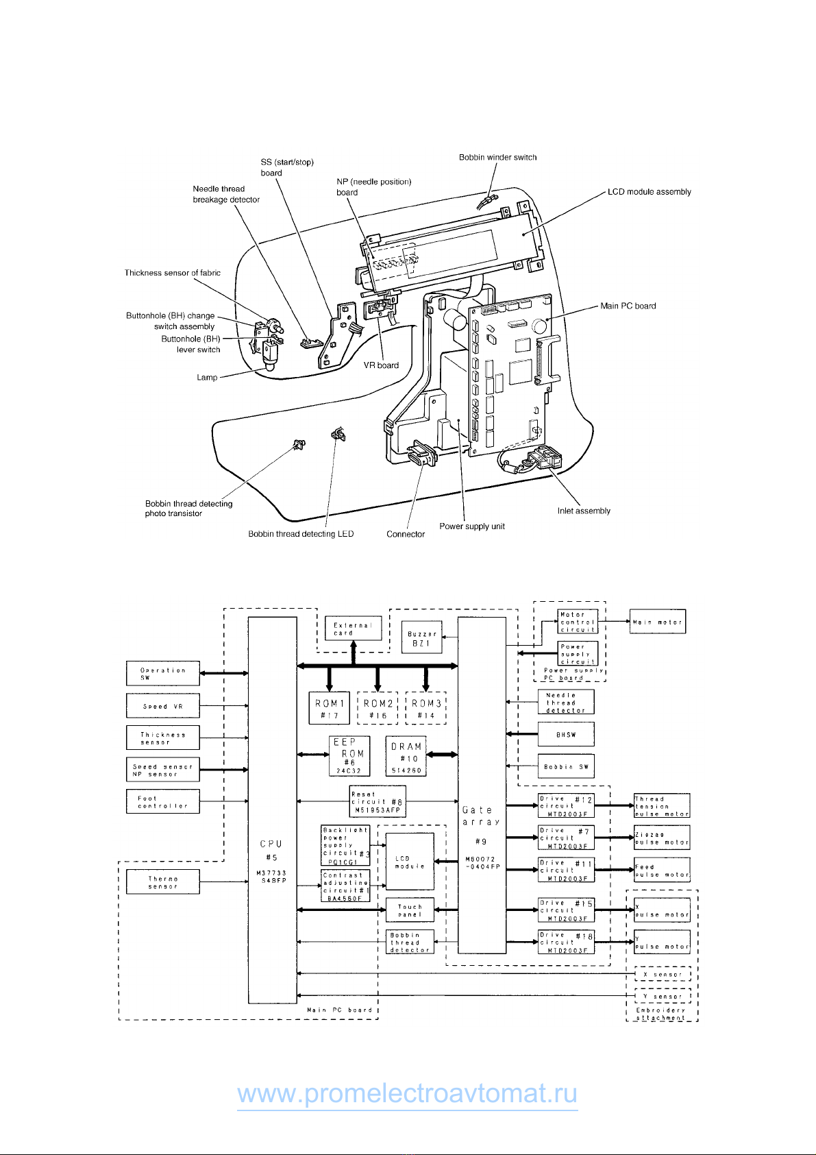
8. OTHER ELECTRONIC COMPONENT FUNCTIONS
Start/stop switch.................................. used to start and stop (SS) the machine. If you want to start sewing at low
speed, keep this switch depressed and start sewing.
Backstitch switch................................. used for backstitching and lockstitching. Backstitching is performed at low
speed in the reverse direction while the switch is pressed. For
lockstitching, three stitches are made at the current needle position and
then sewing stops.
Needle position (UP/DOWN) switch.... used to change the needle position either up or down.
Automatic thread cutter switch............ used to cut the thread automatically. When you press this switch, the
machine will automatically cut the thread, regardless of the needle
position, and stop with the needle at its upper position.
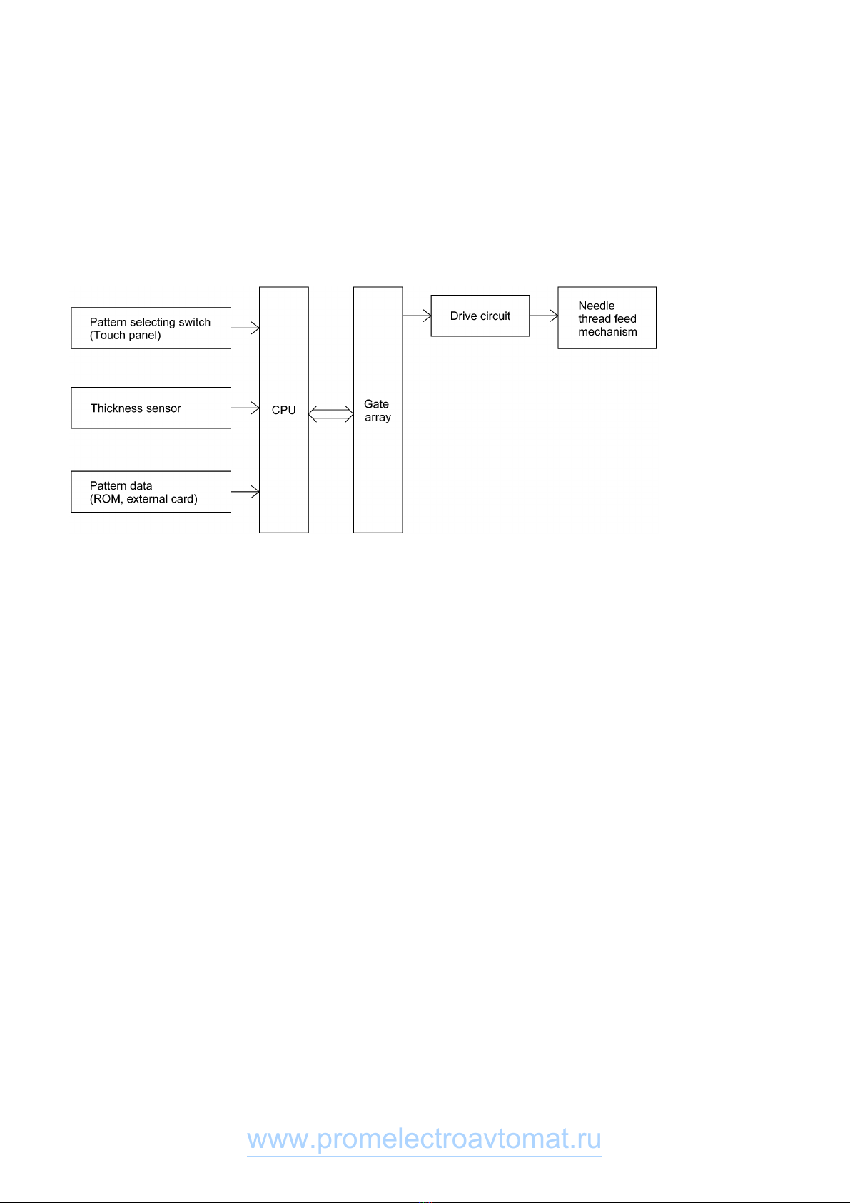
Touch panel......................................... used to select pattern and input number required for sewing by simply
touching the display on the panel. This simplifies the operation for
selecting the desired pattern and number.
Buttonhole stitch switch....................... used to detect the edges of the buttonhole stitch by means of the
buttonhole stitch presser foot and lever.
Buttonhole stitch lever switch.............. used to detect whether the buttonhole stitch lever is raised or lowered.
Rotation sensor ................................... detects the drive timing of the embroidery frame drive, zigzag, feed and
thread feed pules motor and detects the vertical position of the needle.
Also detects the turning angle of the upper shaft by means of a
photointerruptor and shutter installed on the upper shaft.
Speed sensor ...................................... used to detect the rotation speed of the main motor.
detects the operating speed of the main motor by means of a
photointerruptor and shutter installed on the upper shaft.
Bobbin winder switch........................... used to detect whether the bobbin winder has been set when winding the
lower thread.
Junction for foot controller................... when using the foot controller, connect it to this terminal.
Transformer......................................... used for driving the pulse motors, to illuminate the lamps and to supply
power to the electronic circuitry.
Lamp.................................................... is 12V 5W.
www.promelectroavtomat.ru

-9-
1. DISASSEMBLING AND REASSEMBLING THE OUTER PARTS AND MAIN
PARTS
1. Remove the screw securing the face plate, and the face plate by sliding it to the left.
2. Remove the screw securing the free arm cover, and the free arm cover by sliding it to the left.
3. Remove the blind cap on the belt cover, the screw securing the belt cover, and the belt cover from below by
sliding it to the right.
4. Remove the two screws securing the base cover, slide the base cover to the left and then holding the front,
slide it to the left and out.
5. Remove the screw securing the front cover (near spool pin), and loosen the two screws (below jaw section
on face plate side, below free arm). Open the front cover toward the front, remove the four connectors and
then the front cover.
6. Remove the two screws securing the needle plate, and the needle plate.
7. Remove the three screws securing the rear cover, and the rear cover from the rear side.
Disassembly Points
3. To remove the belt cover, unhook the bottom catch (A), slide the belt cover to the right, then unhook the
top catches (B) by sliding the belt cover downward.
5. To remove the front cover, slide part (C) downward, unhook the two catches (F) from the base plate and the jaw
section of the front cover (D) from the bottom of the thread guide, then pull the front cover away at the front.
7. To remove the balance wheel screw (E) securing the rear cover, move the bobbin winder shaft to the right.
∗Before removing the rear cover, lower the presser foot lifter.
www.promelectroavtomat.ru

-10-
8. Remove the presser holder and needle.
9. Remove the 14 connectors, the two screws, and the main PC board.
10. Remove the two screws and handle holder assembly.
11. Remove the screw and thread winding assembly.
12. Remove the motor belt and pull out the motor connector. Remove the two screws and the main motor.
13. Remove the screw and the board set plate D.
14. Remove the side feed plate spring, the three screws and the SPM holder.
15. Remove the two screws, and pull out the thread guide cover from the tension link.
16. Remove the screw and the H block shaft holder assembly.
17. Remove the three springs and the needle bar block assembly.
18. Remove the two screws and the ZPM assembly.
Disassembly Points
9. To disconnect the connectors, grab the base of the connector and pull it straight out.
∗In order to reduce the risk of static electric damage to the main PC board after it is removed from the
sewing machine, do not touch the board’s front surface and only carry it by its edges in the same way
that you hold a compact disk.
15. To remove the thread guard cover from the tension link more easily, cut the band.
15. Before removing the thread guard cover from the tension link, lower the presser foot lifter and move part
(A) of the thread take-up crank so that its front slants upward.
16. To remove the needle bar supporter stud holder, move it upward while removing it from the pin.
17. Before removing the needle bar supporter assembly, remove the two springs (B).
18. Before removing the ZPM holder assembly, remove the lamp cord connector from the power supply PC
board.
www.promelectroavtomat.ru

-11-
www.promelectroavtomat.ru

-12-
19. Remove the two screws and the thread cutter unit.
20. Remove the screw and the inner rotary hook bracket.
21. Remove the presser bar clamp screw.
22. Remove the presser bar by lifting it from above, and the presser bar clamp.
23. Remove the presser spring screw and the presser bar spring.
24. Remove the presser lifter by pulling the presser lifting shaft straight out from the front.
25. Pull the tension releaser plate out forward.
26. Remove the screw and the thread take-up shaft.
Disassembly Point
19. Before removing the thread cutting assembly, move the thread cutter cam so that its notch faces the front
of the sewing machine (A).
www.promelectroavtomat.ru

-13-
27. Remove the two screws securing the upper shaft metal, and the upper shaft assembly.
28. Remove the screw and the N.P. board assembly.
29. Remove the screw and the tension pulley holder.
30. Remove the two feed rod tension springs.
31. Remove the metal presser screw and horizontal feed shaft bracket screw, and then remove the horizontal
feed assembly.
32. Remove the two screws and the drop guide.
33. Remove the two screws and the FPM holder assembly.
34. Remove the screw and the outer rotary hook assembly .
35. Remove the two metal presser screws and remove the lower shaft assembly and the timing belt.
36. Remove the connector, the two screws and the power supply unit assembly.
37. Remove the three screws and base plate assembly.
Disassembly Points
27. To remove the upper shaft assembly more easily, remove the two feed rod tension springs (A) and the
tension pulley assembly (B) first.
∗When removing the upper shaft assembly, do not to bend the NP or rotary shutters.
31. Before removing the horizontal feed assembly, remove the feed bar tension spring (C).
www.promelectroavtomat.ru

-14-
38. Attach the base plate using the three screws.
39. Attach the power supply unit assembly using the two screws and insert the inlet connector.
40. While attaching the timing belt, assembly the lower shaft assembly using the metal presser and screw.
41. Position the outer rotary hook assembly and the three spacers with the lower shaft assembly (refer to
following illustrations) and attach using the screw.
42. Attach the FPM holder assembly using the two screws.
43. Attach the drop guide with the screw.
44. Use the screw to attach the horizontal feed shaft. Use the presser plate and the screw to attach the
horizontal feed assembly. Attach the feed stand spring. Attach the drop plate spring with the screw.
45. Insert the feed rod shaft into the feed block and attach the two feed rod springs.
46. Attach the tension pulley holder with the screw.
47. Attach the NP board assembly with the screw.
48. Run the upper shaft through the timing belt and attach with the two presser plates and the screws.
Assembly Points
40. When attaching the lower shaft assembly, do so with notch of the lower shaft eccentric metal (A) facing
forwards.
40. After lower shaft is attached, make sure that the lower shaft moves freely. If it does not move freely,
lightly tap the lower shaft metal presser (I) with a punch, or similar tool, and check again.
40. When attaching the outer rotary hook assembly, attach so that lower shaft base hole (B) of the thread
cutter cam and the outer rotary hook assembly baseline (C) are positioned towards the front.
41. ∗Attach so that thick end of the rotary hook shaft washer is in on top.
41. ∗Adjust position of notch of eccentric metal to adjust play of the outer rotary hook assembly and the lower
shaft (rotation direction slack of the outer rotary hook assembly). Positioning the notch at the bottom will
reduce play. Under normal conditions, the ideal position is towards the front. However, when play is
excessive, adjust to prevent the rotary hook noise.
42. For the screw on the top of the FPM holder (D), use a 14 mm cap-attached screw.
42. Attach the washer (polywasher) to the right of feed regulator.
42. Push the FPM holder to the left so that there is no slack between feed regulator and fasten with cap-
attached screw. When fastening next the screw, do so without applying force to holder. After fastening,
check movement and slack of feed regulator.
44. For the screw on the left side of the horizontal feed shaft (H), use a screw of 14 mm.
44. Attach so that the feed dog adjustment knob comes to the right.
44. Check back and forth movement of feed stand.
∗If free movement is hindered, feed pitch is inhibited or a forward and backward motion is inhibited.
45. Attach corner panel so that the "S" mark is on the inside (on feed rod side).
45. Attach the feed rod support plate spring (47-1) to support plate.
46. After tension pulley is attached, adjust tension of the timing belt. (see (G) for reference.)
48. When attaching the timing belt, first run corner panel through the timing belt and attach to the feed rod
shaft, then attach the two feed rod springs (46).
∗After attaching the timing belt, adjust rotation torque of the timing belt.
48. When attaching the timing belt, do so when notch (F) of the horizontal feed cam of the timing belt and the
lower shaft baselines (B) and (E) are facing positioned on the front side.
www.promelectroavtomat.ru

-15-
www.promelectroavtomat.ru

-16-
49. Attach the thread take-up shaft using the screw.
50. Insert the tension plate.
51. Attach the presser spring, washer and clip using the collar and screw.
52. Attach the lifter and the presser foot lifter with the presser foot shaft.
53. Insert and attach the presser bar into the presser bar clamp.
54. Attach the presser bar spring onto the presser bar clamp.
55. Attach the inner rotary hook rotation prevention plate using the screw.
56. Attach the thread cutter unit using the two screws.
Assembly Points
49. The screw (49) used to install the thread take-up lever shaft should have a nominal length of 14 mm.
∗The thread take-up lever shaft should be installed so that there is no gap between the right side of the
thread take-up and the stop ring. If there is a large gap, the right and left clearance may generate an
irregular noise (thread take-up lever noise).
55. Install the inner rotary hook bracket assembly. (Firmly tighten the screw to make no space between (D)
and the arm so that the inner rotary hook bracket assembly does not rotate.)
∗After the inner rotary hook bracket assembly is installed, adjust the position where rotation is prevented.
(Refer to (A).)
∗If there is a small rotation prevention amount, the inner rotary hook may slip and start rotating causing
damage to the inner rotary hook or breaking the needle.
56. Before installing the thread cutting assembly, move the thread cutter cam so that its notch faces the front
(B) of the sewing machine.
56. Thread cutting assembly installation procedure
(1) Insert the projection (C) on the cutter unit into the arm guide hole.
(Insert the projection while checking that the inner rotary hook is correctly positioned.)
(2) Move the thread cutting assembly toward the right without bending the lower thread guide arm assembly
to install it.
∗After installing the thread cutting assembly, perform the following procedure to check that the movable
blade operates correctly.
(1) With the lever pin pressed in by hand, turn the balance wheel by hand to begin operating the movable
blade.
(2) When the movable blade is at its rightmost position, release the lever pin and turn the balance wheel, then
check that the movable blade lightly returns to its previous position.
∗If the movable blade does not operate correctly, loosen the screw (56), move the thread cutting
assembly forward and backward, then move the unit toward the right and tighten the screw.
www.promelectroavtomat.ru

-17-
www.promelectroavtomat.ru

-18-
57. Attach the ZPM holder assembly using the two screws.
58. Attach the needle bar supporter assembly using the two springs. (Insert into the needle bar clamp and
needle bar crank rod)
59. Attach the needle bar supporter stud holder using the screw. (Insert the needle bar supporter arm into the
pin on the needle bar supporter.)
60. While inserting the thread guide cover assembly into the thread release link attach using the two screws.
61. Attach the SPM holder assembly using the three screws, and couple the horizontal feed plate and vertical
feed plate using the horizontal feed plate spring.
62. Attach the set plate D using the screws.
63. Connect the motor connector, attach the main motor using the two screws and catch the motor belt.
64. Attach the bobbin winder assembly using the screws.
65. Attach the handle holder assembly using the two screws.
66. Attach the main board assembly using the two screws. Connect the 14 connectors.
67. Attach the presser holder and needle.
Assembly Points
57. When installing the ZPM holder assembly, the cloth selecting sensor lever should be put on the presser
bar clamp.
∗If the cloth selecting sensor lever slips down, the cloth selecting sensor cannot operate and the thread
tension cannot be adjusted.
58. Before installing the needle bar supporter assembly, insert it into the needle bar crank rod, insert the
needle bar supporter stud holder, then install a spring. Hook the longer end of the other spring (F) to the
main unit.
59. Install the needle bar supporter stud holder from the needle bar supporter pin side, then attaching it using
a 14 mm screw.
60. Before installing the thread guard cover, lower the presser foot lifter and move part (A) of the thread take-
up crank so that its front slants upward.
63. Apply a pressure of 2N (200 g) at the center of the motor belt, then adjust its tension until it only moves 4
to 6 mm (B).
∗If the belt is too tight, the torque becomes too much, causing the motor to rotate slower and generate an
irregular noise. If the tension is too loose, the belt may jump and the upper shaft may not rotate smoothly
while sewing on denim and other thicker fabrics or overlapping fabrics.
64. When installing the bobbin winder assembly, align the tab (C) in the bobbin winder assembly holder with
the positioning hole in the sewing machine.
66. When installing the main PC board, insert the bottom left section of the PC board into the notch (D) in the
SPM holder assembly.
66. Insert the connectors correctly and pass the lead wires under the guides (E).
67. When installing the presser holder, install the presser foot lifter.
www.promelectroavtomat.ru
Table of contents
Other Brother Industries Sewing Machine manuals