– 1 –
1. SPECIFICATIONS
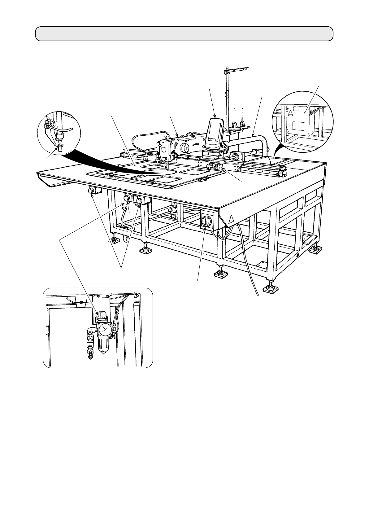
I. MECHANICAL SECTION (WITH REGARD TO THE SEWING MACHINE)
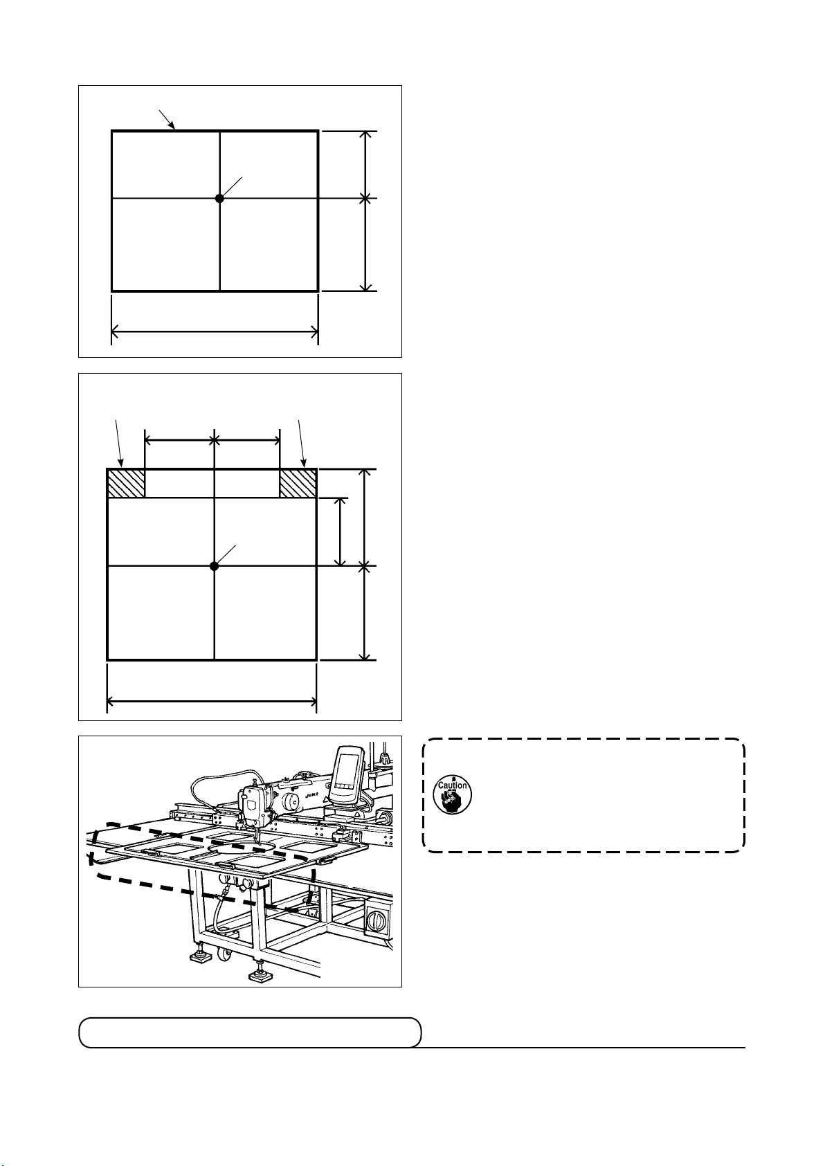
1 Sewing area
Standard sewing area at the time of shipment
X direction 600 mm × Y direction 500 mm
Largest possible sewing area
X direction 600 mm × Y direction Max. 600 mm
2 Max. sewing speed 2,000 sti/min (When sewing pitch is 3 mm or less)
3 Stitch length 0.1 to 12.7 mm (in increments of 0.05 mm)
4 Feed system Intermittent X-Y linear system (with an encoder) driven by the stepping motor
5 Needle bar stroke 41.2 mm
6 Needle
Sewing specication
DP x 17 (B point) (Standard #24) (135×17 FG)
Pneumatic reverse feed type Applicable count of thread: 840 to 1860 denier
7Feeding frame specication Cassette holder of auto-ejector type
8 Intermediate presser stroke 4 mm (Standard) (0 to 10 mm)
9 Lift of intermediate presser 15 mm
10 Intermediate presser
DOWN position variable
0 to 4.0 mm
11 Shuttle Double-capacity semi-rotary hook
12 Lubricating oil New Defrix Oil No. 2 (Lubrication system)
Grease: JUKI GreaseA, PenetrationNo2 lithium Grease, JUKI GreaseB、
LONGTERM W2 (feed rack & pinion, auto-ejector)
13 Memory of pattern data Main body, medium
• Main body : Max. 999 patterns (Max. 50,000 stitches/pattern)
• Medium:Max. 999 patterns (Max. 50,000 stitches/pattern)
14 Start switch Two-hand control start switch
15 Temporary stop facility Used to stop machine operation during a stitching cycle.
16 Enlarging / Reducing facility Allows a pattern to be enlarged or reduced on the X axis and Y axis independently
when sewing a pattern. Scale : 1% to 400% times (0.1% steps)
17 Enlarging / Reducing
method
Pattern enlargement / reduction can be done by increasing / decreasing either stitch
length or the number of stitches. (Increasing/decreasing stitch length only can be
performed when pattern button is selected.)
18 Max. sewing speed
limitation
200 to 2,000 sti/min (Scale : 100 sti/min steps)
19 Pattern selection facility Pattern No. selection method (Main body :1 〜999、Medium:1〜999)
20 Bobbin thread counter UP/DOWN method (0 to 9,999)
21 Sewing counter UP/DOWN method (0 to 9,999)
22 Memory back-up In case of a power interruption, the pattern being used will automatically be stored in
memory.
23 2nd origin setting facility Using jog keys, a 2nd origin (needle position after a sewing cycle) can be set in the
desired position within the sewing area. The set 2nd origin is also stored in memory.
24 Sewing machine motor Servo-motor
25
Dimensions 1,800mm (W) x 2,100mm (L) x 1,275mm (H) (Excluding thread stand)
26 Mass (gross mass) 710 kg
27 Power consumption 550 VA
28 Operating temperature
range
5˚C to 35˚C
29 Operating humidity range 35 % to 85 % (No dew condensation)
30 Line voltage Rated voltage ±10% 50 / 60 Hz
31 Air pressure used 0.5 to 0.55 MPa (Max. 0.55 MPa)
32 Air consumption 1.8 dm3 / min (ANR)
33 Needle highest position
stop facility
After the completion of sewing, the needle can be brought up to its highest position.
34 Noise - Equivalent continuous emission sound pressure level (LpA) at the workstation :
A-weighted value of 85 dB ; (Includes KpA = 2.5 dB) ; according to ISO 10821- C.6.3
-ISO 11204 GR2 at 2,000 sti/min.
- Sound power level (LWA) :
A-weighted value of 94 dB ; (Includes KWA = 2.5 dB) ; according to ISO 10821- C.6.3
-ISO 3744 GR2 at 2,000 sti/min.
(Dust prevention mat (accessory) is used.)