Brother HL-2600CN Series User manual

visit our website at
www.mitsubishi-tv.com
Owner’s Guide
Projection Television Models
WD-52627, WD-62627
TV Information:
Use this space to record the model and serial numbers of
your television. This information is on the back of your TV
Model number
Serial number
TM
TM
TM
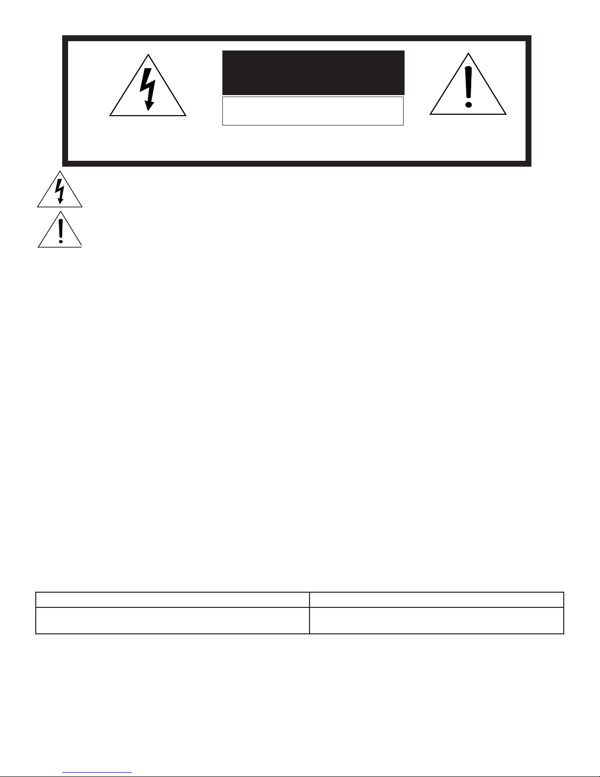
The lightning flash with arrowhead symbol within an equilateral triangle is intended to alert the user of
the presence of uninsulated “dangerous voltage” within the product’s enclosure that may be sufficient
magnitude to constitute a risk of electric shock.
The exclamation point within an equilateral triangle is intended to alert the user to the presence of
important operating and maintenance (servicing) instructions in the literature accompanying the appliance.
WARNING: TO REDUCE THE RISK OF FIRE OR ELECTRIC SHOCK, DO NOT EXPOSE THIS APPLIANCE TO RAIN OR
MOISTURE.
CAUTION: TO PREVENT ELECTRIC SHOCK, MATCH WIDE BLADE OF PLUG TO WIDE SLOT, FULLY INSERT.
NOTE TO CATV SYSTEM INSTALLER: THIS REMINDER IS PROVIDED TO CALL THE CATV SYSTEM INSTALLER’S
ATTENTION TO ARTICLE 820-40 OF THE NEC THAT PROVIDES GUIDELINES FOR THE PROPER GROUNDING AND,
IN PARTICULAR, SPECIFIES THAT THE CABLE GROUND SHALL BE CONNECTED TO THE GROUNDING SYSTEM OF
THE BUILDING, AS CLOSE TO THE POINT OF CABLE ENTRY AS PRACTICAL.
CAUTION
RISK OF ELECTRIC SHOCK
DO NOT OPEN
CAUTION: TO REDUCE THE RISK OF ELECTRIC SHOCK, DO NOT REMOVE COVER (OR
BACK). NO USER SERVICEABLE PARTS INSIDE. REFER SERVICING TO QUALIFIED SERVICE
PERSONNEL.
This TV is heavy! Exercise extreme care when lifting or moving. Lifting or moving the TV requires a
minimum of two adults. To prevent damage to your TV, your TV should not be jarred or moved while it is
turned on. Power off your TV before moving it.
Portions of the advanced circuitry of this TV must continue to operate even when the TV is turned off.
Some of these circuits therefore need to be cooled at all times. A low power standby fan may be heard in
a quiet environment. This is normal operation.
Custom cabinet installation must allow for proper air circulation around the television.
TV Guide On Screen® Access Requirements
TV Guide On Screen listings are not provided by Mitsubishi Digital Electronics America, Inc. Operation of TV Guide
On Screen requires over-the-air or cable access to stations carrying TV Guide On Screen program listings. If listings
are not available in your area or become discontinued by the local provider, TV Guide On Screen will not operate. TV
Guide On Screen does not provide program listings for satellite TV systems.
Stand Requirement
CAUTION: Mitsubishi TV model WD-52627 is for use only with Mitsubishi stand model MB-52527. Mitsubishi TV
model WD-62627 is for use only with Mitsubishi stand model MB-62527. Use with other stands is capable of resulting
in instability causing possible injury.
Lamp Replacement
The image on this TV is produced by a high-brightness lamp that will operate for many hours. Eventually, however, this
lamp will need to be replaced. It is designed to be easily replaced by the TV owner. Front panel indicators and/or on-
screen messages will assist you in determining when the lamp needs to be replaced. Please see Appendix H for details
on lamp replacement.
To order a new lamp:
While Under Warranty After Warranty
Call (800) 332-2119. Please have model number, serial
number, and TV purchase date available.
Call (800) 553-7278. Order lamp part number
915P026010.

FCC Declaration of Conformity
Product: Projection Television Receiver
Models: WD-52627, WD-62627
Responsible Party: Mitsubishi Digital Electronics America, Inc.
9351 Jeronimo Road
Irvine, CA 92618-1904
Telephone: 949-465-6000
This device complies with Part 15 of the FCC Rules. Operation is subject to the following two conditions:
(1) This device may not cause harmful interference, and
(2) this device must accept any interference received, including interference that may cause undesired operation.
Note: This equipment has been tested and found to comply with the limits for a Class B digital device, pursuant to
part 15 of the FCC Rules. These limits are designed to provide reasonable protection against harmful interference in
a residential installation. This equipment generates, uses and can radiate radio frequency energy and, if not installed
and used in accordance with the instructions, may cause harmful interference to radio communications. However,
there is no guarantee that interference will not occur in a particular installation. If this equipment does cause harmful
interference to radio or television reception, which can be determined by turning the equipment off and on, the user
is encouraged to try to correct the interference by one or more of the following measures:
• Reorient or relocate the receiving antenna.
• Increase the separation between the equipment and the receiver.
• Connect the equipment into an outlet on a circuit different from that to which the receiver is connected.
• Consult the dealer or an experienced radio/TV technician for help.
CAUTION: To ensure continued FCC compliance, the user must use a shielded video interface
or HDMI cable with bonded ferrite cores at both ends when using the PC input.
Changes or modifications not expressly approved by Mitsubishi could cause harmful interference and would
void the user’s authority to operate this equipment.
4
IMPORTANT SAFEGUARDS
Please read the following safeguards for your TV and retain for future reference. Always follow all
warnings and instructions marked on the television.
1. Read, Retain and Follow All Instructions
Read all safety and operating instructions before operating the TV. Retain the safety and operating instructions
for future reference. Follow all operating and use instructions.
2. Heed Warnings
Adhere to all warnings on the appliance and in the operating instructions.
3. Cleaning
Unplug the TV from the wall outlet before cleaning. Do not use liquid, abrasive or aerosol cleaners. Cleaners can
permanently damage the cabinet and screen. Use a lightly dampened cloth for cleaning.
4. Attachments and Equipment
Never add any attachments and/or equipment without approval of the manufacturer as such additions may result
in the risk of fire, electric shock or other personal injury.
5. Water and Moisture
Do not use the TV where contact with or immersion in water is possible. Do not use near bath tubs, wash bowls,
kitchen sinks, laundry tubs, swimming pools, etc.
6. Accessories
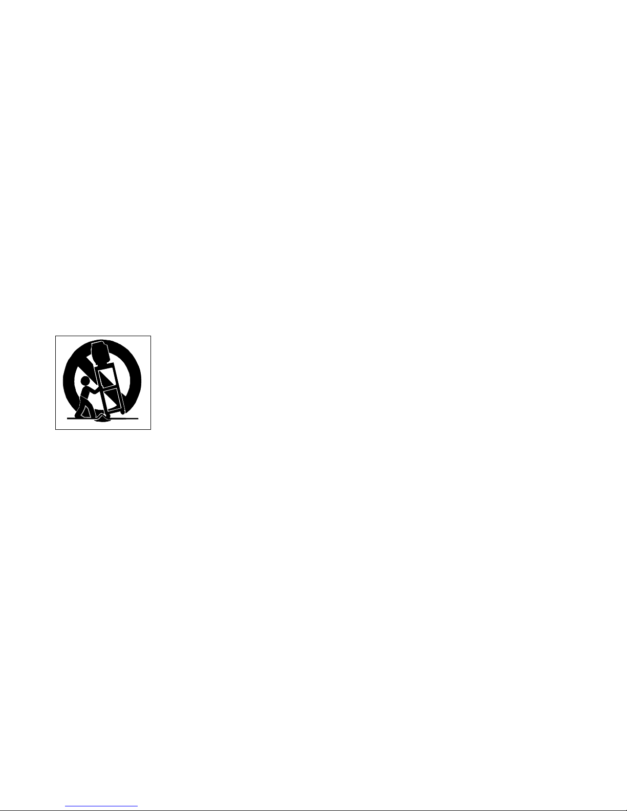
Do not place the TV on an unstable cart, stand, tripod, or table. The TV may fall, causing
serious injury to a child or adult and serious damage to the TV. Use only with a cart, stand,
tripod, bracket or table recommended by the manufacturer, or sold with the TV. Any mounting
of the TV should follow the manufacturer’s instructions, and should use mounting accessories
recommended by the manufacturer.
An appliance and cart combination should be moved with care. Quick stops, excessive force,
and uneven surfaces may cause the appliance and cart combination to overturn.
7. Ventilation
Slots and openings in the cabinet are provided for ventilation and to ensure reliable operation of the TV and to
protect it from overheating. Do not block these openings or allow them to be obstructed by placing the TV on a
bed, sofa, rug, or other similar surface. Nor should it be placed over a radiator or heat register. If the TV is to be
placed in a rack or bookcase, ensure that there is adequate ventilation and that the manufacturer’s instructions
have been adhered to.
8. Power Source
This TV should be operated only from the type of power source indicated on the marking label. If you are not sure
of the type of power supplied to your home, consult your appliance dealer or local power company.
9. Grounding or Polarization
This TV is equipped with a polarized alternating current line plug having one blade wider than the other. This plug
will fit into the power outlet only one way. If you are unable to insert the plug fully into the outlet, try reversing the
plug. If the plug should still fail to fit, contact your electrician to replace your obsolete outlet. Do not defeat the
safety purpose of the polarized plug.
10. Power-Cord Protection
Power-supply cords should be routed so that they are not likely to be walked on or pinched by items placed
upon or against them, paying particular attention to cords at plugs, convenience receptacles, and the point
where they exit from the TV.
11. Lightning
For added protection for this TV during a lightning storm, or when it is left unattended and unused for long
period of time, unplug it from the wall outlet and disconnect the antenna or cable system. This will prevent
damage to the TV due to lightning and power-line surges.
5
IMPORTANT SAFEGUARDS, continued
12. Power Lines
An outside antenna system should not be located in the vicinity of overhead power lines or other electric light or
power circuits, or where it can fall into such power lines or circuits. When installing an outside antenna system,
extreme care should be taken to keep from touching such power lines or circuits as contact with them might be
fatal.
13. Overloading
Do not overload wall outlets and extension cords as this can result in a risk of fire or electric shock.
14. Object and Liquid Entry
Never push objects of any kind into this TV through openings as they may touch dangerous voltage points or short-
out parts that could result in fire or electric shock. Never spill liquid of any kind on or into the TV.
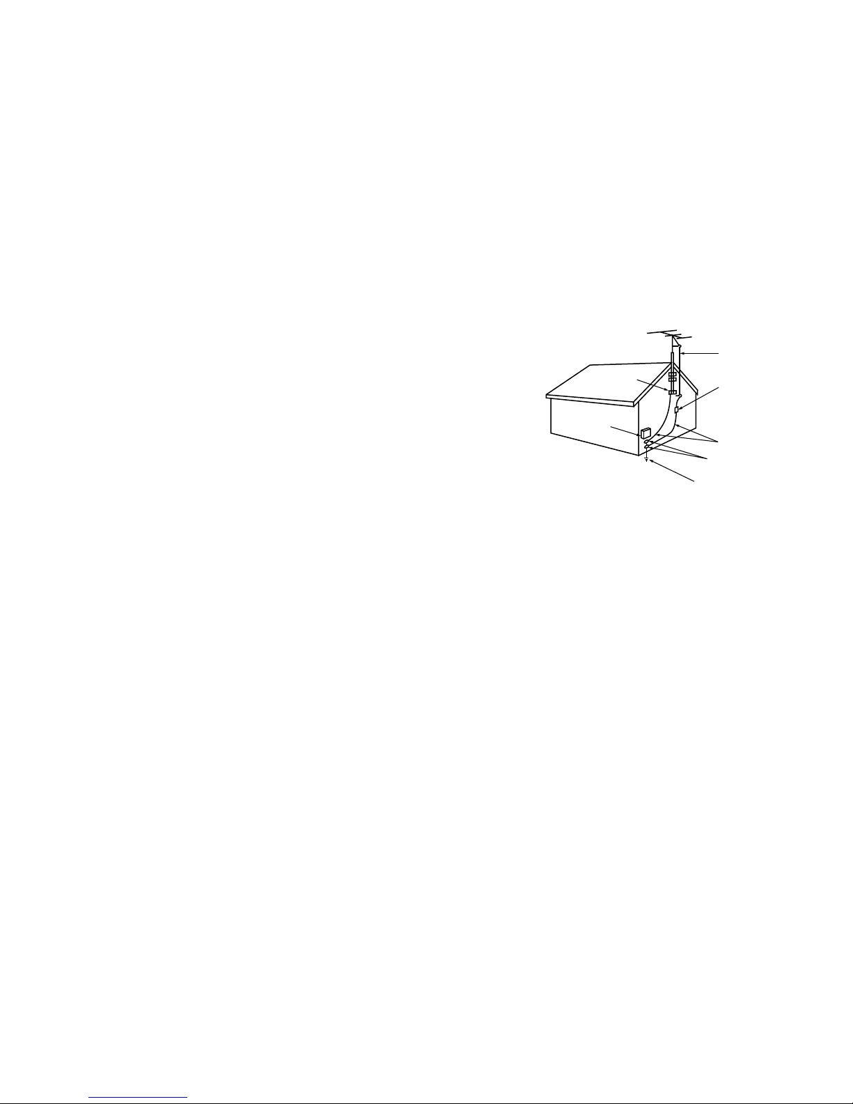
15. Outdoor Antenna Grounding
If an outside antenna or cable system is connected to the TV, be sure the
antenna or cable system is grounded so as to provide some protection
against voltage surges and built-up static charges.
Article 810 of the National Electric Code, ANSI/NFPA No. 70-2002,
provides information with respect to proper grounding of the mast
and supporting structure, grounding of the lead in wire to an antenna
discharge unit, size of grounding conductors, location of antenna
discharge unit, connection to grounding electrodes, and requirements
for the grounding electrode.
16. Servicing
Do not attempt to service this TV yourself as opening or removing covers may expose you to dangerous voltage
or other hazards. Refer all servicing to qualified service personnel.
17. Damage Requiring Service
Unplug the TV from the wall outlet and refer servicing to qualified service personnel under the following
conditions:
(a) When the power-supply cord or plug is damaged.
(b) If liquid has been spilled, or objects have fallen into the TV.
(c) If the TV has been exposed to rain or water.
(d) If the TV does not operate normally by following the operating instructions, adjust only those controls that are
covered by the operating instructions as an improper adjustment of other controls may result in damage and
will often require extensive work by a qualified technician to restore the TV to its normal operation.
(e) If the TV has been dropped or the cabinet has been damaged.
(f) When the TV exhibits a distinct change in performance - this indicates a need for service.
18. Replacement Parts
When replacement parts are required, be sure the service technician has used replacement parts specified by the
manufacturer or have the same characteristics as the original part. Unauthorized substitutions may result in fire,
electric shock or other hazards.
19. Safety Check
Upon completion of any service or repair to the TV, ask the service technician to perform safety checks to determine
that the TV is in safe operating condition.
20. Heat
The product should be situated away from heat sources such as radiators, heat registers, stoves or other products
(including amplifiers) that produce heat.
AN T E N NA
LE AD IN W IR E
AN T E N NA
DIS C H AR G E U NIT
(NE C AR T I C L E 810-2 0)
G R O UN DING
C O N DU C T O R S
(NE C AR T I C L E 810-2 1)
G R O UN D C L AMP S
P OWE R S E R V IC E G R OUND ING
E LE C T R ODE S Y S TE M
(NE C AR T 250, P AR T H)
G R O UN D C L AMP
E LE C T R IC
S E R V I C E
E Q UIP ME N T
NE C — NAT ION AL E LE C T R IC AL C ODE
E X AMP L E O F ANT E NN A G R O UND ING

Contents
Chapter 1: Television Overview
TV Accessories ..................................................................... 10
Special Features .................................................................... 11
Front Control Panel ................................................................. 12
Remote Control
Overview ....................................................................... 14
Battery Installation .............................................................. 15
Care ........................................................................... 15
Sleep Timer ..................................................................... 15
TV Back Panel...................................................................... 16
Media Card Slots ................................................................... 18
Front-Panel Input 3.................................................................. 18
Using the System Reset Button....................................................... 19
Using the Reset Menu to Reset the TV ................................................ 19
Chapter 2: Connecting
External Devices and NetCommand® Setup ........................................... 22
CableCARD™ Technology ........................................................... 23
Wall Outlet Cable ................................................................... 24
Standard Cable Box................................................................. 24
Antenna with a Single Lead .......................................................... 25
Antennas with Separate UHF and VHF Leads .......................................... 25
VCR to an Antenna or Wall Outlet Cable (Audio & Video)................................. 26
VCR to a Cable Box (Audio & Video)................................................... 27
A/V Receiver (Stereo System) ........................................................ 28
Satellite Receiver or Other Device with S-Video ........................................ 28
DVD Player with Component Video ................................................... 29
DVI Device ......................................................................... 29
HDTV Cable Box or Satellite Receiver with Component Video ........................... 30
HDMI Device ....................................................................... 30
Computer with an HDMI Monitor Output............................................... 31
Computer with a DVI Monitor Output .................................................. 31
IR Emitter NetCommand® ........................................................... 32
Compatible IEEE 1394 Devices ....................................................... 33
Helpful Hints ....................................................................... 35
Chapter 3: NetCommand® Setup and Editing
NetCommand® Introduction ......................................................... 38
Using the Remote Control with NetCommand® ........................................ 39
NetCommand® Setup On-Screen Buttons............................................. 40
3D Graphical Menu System ................................................... 41
NetCommand® Initial Setup ......................................................... 42
Edit NetCommand®: Add an A/V Receiver ............................................ 45
Edit NetCommand®: Add Devices ................................................... 48
Edit NetCommand®: Change or Delete Devices ....................................... 52

Chapter 4: IEEE 1394 Devices and NetCommand®-Controlled Recordings
IEEE 1394 Devices and NetCommand® Control ........................................ 54
Adding IEEE 1394 Devices Automatically .............................................. 55
Device Selection Menu .............................................................. 57
Using the Device Menu Button to Display Menus ....................................... 58
Using the GUIDE Button to Display ChannelView™ and Menus .......................... 59
NetCommand®-Controlled Recordings ............................................... 60
Chapter 5: TV Menu Screen Operations
Main Menu ......................................................................... 64
Setup Menu ....................................................................... 65
NetCommand® Menu .............................................................. 67
Record Menu....................................................................... 68
Channel Menu ..................................................................... 70
Captions Menu ..................................................................... 72
V-Chip Lock Menu .................................................................. 74
Audio/Video Menu .................................................................. 77
A/V Setting Descriptions: Audio...................................................... 78
A/V Setting Descriptions: Video ...................................................... 79
Chapter 6: Additional Features
Operation of PIP .................................................................... 82
TV Display Formats ................................................................. 83
PC Viewing......................................................................... 85
PC Display Formats ................................................................. 86
MediaCommand™ and Media Card Playback .......................................... 87
Chapter 7: Troubleshooting........................................................ 89
Appendices
Appendix A: Bypassing the V-Chip Lock .............................................. 97
Appendix B: Specifications .......................................................... 99
Appendix C: Remote Control Programming Codes .................................... 101
Appendix D: Device Control with NetCommand® ..................................... 104
Appendix E: NetCommand® Specialized Device Keys ................................. 106
Appendix F: On-Screen Information Displays ......................................... 107
Appendix G: Cleaning and Service .................................................. 108
Appendix H: Lamp Cartridge Replacement........................................... 109
Trademark and License Information ............................................. 111
Index .................................................................................. 113
Mitsubishi DLP™ Projection Television Limited Warranty .................... 115

8
Our Thanks...
Thank you for choosing Mitsubishi as your premier Home Entertainment provider
This Owner’s Guide describes the features and functions of your Mitsubishi
widescreen, high definition TV. We urge you to examine this Owner’s Guide to
become familiar with the innovative features and operations this unique television
offers.
The very core of our corporate philosophy is to provide our customers with the
very best. Our development team at Mitsubishi has worked to provide you with
a television that defines “state-of-the-art,” with the capability to meet your needs
now and in the future.
Whether this is your first Mitsubishi electronic product, or an addition to your
Mitsubishi collection, we believe you and your family will continue to enjoy your
Mitsubishi home theater for many years.
Thank you,
Mitsubishi Digital Electronics America, Inc.

Chapter . . . 1
Television Overview
TV Accessories .................................... 10
Special Features.................................... 11
Front Control Panel.................................. 12
Remote Control
Overview........................................ 14
BatteryInstallation.................................. 15
Care........................................... 15
SleepTimer ...................................... 15
TV Back Panel ..................................... 16
Media Card Slots ................................... 18
Front-Panel Input 3 .................................. 18
Using the System Reset Button ......................... 19
Using the Reset Menu to Reset the TV .................... 19

10 Chapter 1. Television Overview
TV Accessories
Please take a moment to review the following
list of items to ensure that you have received
everything including:
108&3
)0.&
1"64&
3&$
'''8%3&83&7 1-":
4501
27
70-6.&
*/'0
&9$)
&/5&3
57.&/6 %&7*$&
.&/6
7$)*1
'03."5
1*1$)
427
%&7*$&
4-&&1
7*%&0
"6%*0
.65&
$)"//&-
"%+645
1*1
1*1%&7*$&
$"/$&-
57 "6%*0
$"#-&%#4%57 %7%
7$3
(6*%&
46#
$0//&$5
1"(&
AAA
AAA
1. Remote Control
2. Two AAA Batteries
3 One Double IR Emitter Cable (allows NetCommand
to control other devices)
4. Product Registration Card (not pictured)
5. Owner’s Guide (not pictured)
6. Quick Reference Card (not pictured)
7. TV Guide On Screen® Interactive Program Guide
User’s Manual (not pictured)

Chapter 1. Television Overview 11
Special Features
Your new High Definition widescreen television has many special features that make it the perfect center of
your home entertainment system, including:
High Definition DLP™ Display System
Your widescreen Mitsubishi HDTV uses Texas Instruments most advanced Digital Light Processing™ technology
for rear projection televisions. This TV is truly a high-performance multimedia monitor uniquely capable of both
stunning high-definition video images and clear, detailed, high-resolution PC images. Your TV is able to accept
video signals from an antenna or direct cable in standard video scanning rates of 480i, 480p, 720p, 1080i and
1080p. It is also able to accept, through the HDMI 2 connection, signals with PC resolutions from VGA (640 x 480)
through XGA (1024 x 768). When used with a compatible graphics card and controlling software, this TV is also
able to accept the custom PC resolution of 720p (1280 x 720). When connecting a PC to HDMI you will need a PC
video card with DVI or HDMI output. Also, so the TV can apply the correct PC signal processing, you will need to
set up the TV to receive the PC signals through the HDMI 2 input by using the NetCommand setup system. All of the
compatible video and PC signals will be converted to 1080p for final display; some signals will, however, add black
side bars, top and bottom bars, or both to fill the screen, and some signals will display standard video overscan.
TV Guide On Screen® Interactive Program Guide System
An eight-day on-screen program guide that can be used with cable, over-the-air and CableCARD™ reception. The
subscription-free guide system lists regular, digital and high-defintion programming. This system allows multiple
sorting options and easy program recording. Program listings are downloaded while your TV is turned off, so that
you have current program information available every day. Note that when the system is first set up, it may take up
to 24 hours to begin to receive TV program listings. It may take one week to receive all eight days of TV program
listings.
Digital Cable Ready (CableCARD™)
Your widescreen Mitsubishi HDTV is “Plug-and-Play” ready. It can descramble a cable provider’s one-way digital
signals with the use of a CableCARD security module. The CableCARD is used in place of a traditional cable box
to access digital cable programming (including high definition). Contact your local cable provider for availability
information and service details.
NetCommand®Home Network Control System
Your widescreen Mitsubishi HDTV offers a new level of networking to combine selected older products with new
and future digital products. NetCommand supports IEEE 1394 connections, Audio Video Control system (AV/C),
5C copy protection and IR control of selected older products such as VCRs, DVD players, cable boxes or satellite
receivers. NetCommand includes the ability to learn remote control signals directly from many devices, allowing you
to customize the NetCommand system in a way that works best for your viewing
16:9 Widescreen Picture Format
Enjoy a full theatrical experience in the comfort of your home. View pictures as film directors intended them. Digital
TV broadcasts, DVDs and newer video game consoles support this widescreen format.
Media Cards
You can display a slide show of your favorite JPEG pictures or listen to MP3 or WMA audio selections that have been
recorded on compatible media cards
12 Chapter 1. Television Overview
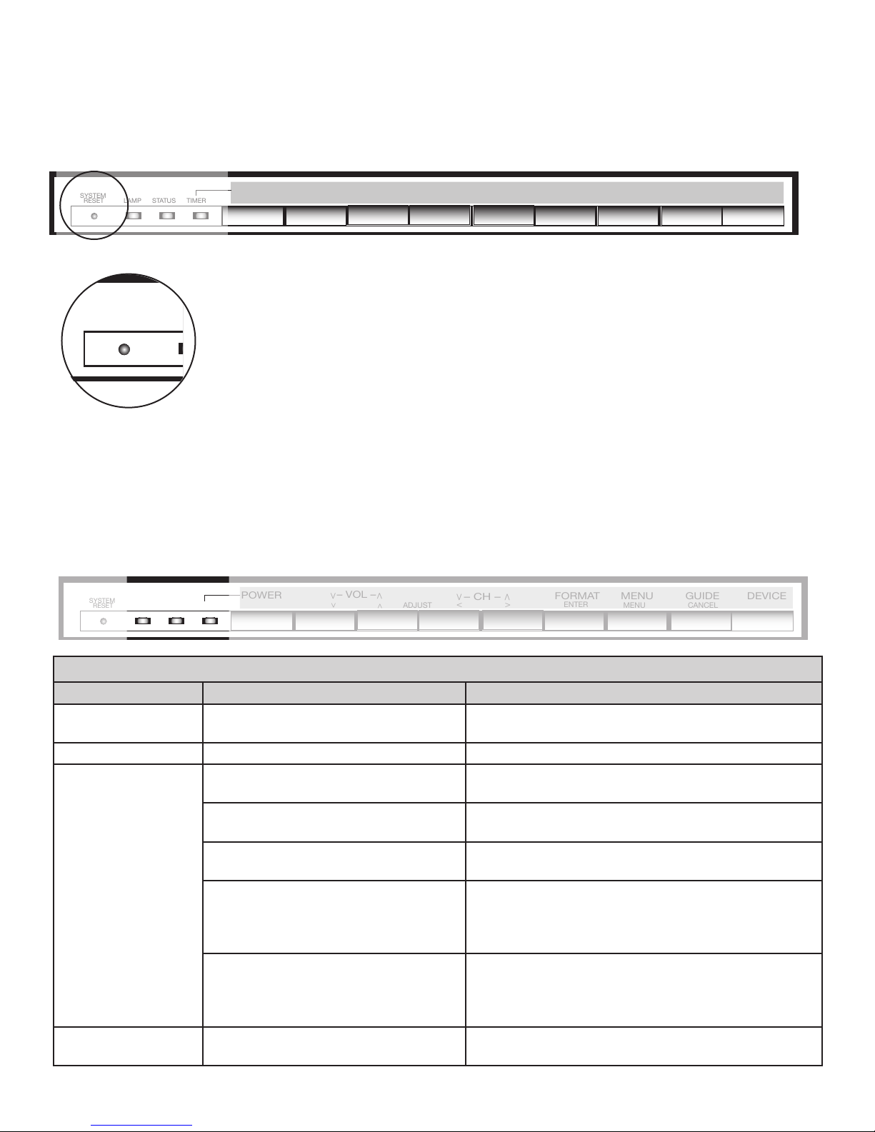
Front Control Panel
The shaded buttons on the front control panel are duplicated on the remote control. The top row of labels shows the
control functions when there are no TV menus displayed on the screen. The bottom row of labels shows the control
functions when the TV menus are displayed on the screen or when a special function has been activated. See
“Remote Control Overview” for further details on the functions of these buttons.
<
DEVICEGUIDE
CANCEL
MENU
ENTER
MENUFORMAT
– CH –
<
>
ADJUST
– VOL –
<
>
>
< >
POWER
SYSTEM
RESET LAMP STATUS TIMER
System Reset
If the TV does not respond to either the remote control or the front panel controls and/or
does not power Off, press the SYSTEM RESET button with a pointed item like the end
point of a paperclip. The TV will turn Off and the TIMER light will flash quickly for about
one minute. When the TIMER light stops flashing, you may again turn on the TV. The
changes you made the last time the TV was on before you used the SYSTEM RESET
button may be lost; any changes that were previously saved are not lost, however.
<
DEVICEGUIDE
CANCEL
MENU
ENTER
MENUFORMAT
– CH –
<
>
ADJUST
– VOL –
<
>
>
< >
POWER
SYSTEM
RESET LAMP STATUS TIMER
A/V Reset
There may be times when you wish to reset the A/V (Audio and Video) settings back to the factory defaults. To
return all of the settings at once, press GUIDE and FORMAT on the front panel at the same time. To reset the
defaults for individual devices, use the A/V Memory Reset selection on the Audio/Video menu.
<
DEVICEGUIDE
CANCEL
MENU
ENTER
MENUFORMAT
– CH –
<
>
ADJUST
– VOL –
<
>
>
< >
POWER
SYSTEM
RESET LAMP STATUS TIMER
Front-Panel Indicator Lights
Power/Timer Indicator
Indicator Color TV Condition Additional Information
None (indicator
off)
TV is powered OFF. Normal operation.
Green, steady TV is powered ON. Normal operation.
Green, rapid
blinking
1. TV just plugged into AC outlet. Wait until blinking stops before turning on
(approximately 1 minute). Normal operation.
2. AC just restored after power failure. Wait until blinking stops before turning on
(approximately 1 minute). Normal operation.
3. TV Rebooting after System Reset
used.
Wait until blinking stops before turning on
(approximately 1-2 minutes). Normal operation.
4. TV Rebooting after power
fluctuation or receiving abnormal
digital signals from digital channel,
CableCARD™, or digital device.
Wait until blinking stops before turning on
(approximately 1 minute). Normal operation.
5. You have begun the procedure to
update software from an authorized
flash memory device.
For detailed information, see the instructions
that accompany the authorized software update.
Important: Do not use non-authorized software at
any time.
Green, slow
blinking
TV powered off and automatic-on
timer is set.
Normal operation. TV can be turned on at any
time.

Chapter 1. Television Overview 13
Status Indicator
Indicator Color TV Condition Additional Information
None (indicator
off)
Normal TV on or standby condition. Normal operation.
Yellow, steady Room temperature is too high. TV will not operate when the ambient room
temperature is too high. Turn off the TV and wait
until the room temperature drops.
Red, either steady
or blinking
TV may require service. Turn off the TV and unplug the set from the AC power
source. Wait one minute and then plug the set back
in.
If the LED is still on, contact your dealer or a
Mitsubishi Authorized Service Center. See www.
mitsubishi-tv.com or call 1-800-332-2119 to receive
Authorized Service Center information.
Lamp Indicator
Indicator Color TV Condition Additional Information
None (indicator
off)
Normal TV on or standby condition. Normal operation.
Green, rapid
blinking
TV just powered off and lamp is
cooling.
Begins to blink 30 seconds after turning off TV.
TV can be turned on before it begins to blink or
after the blinking stops, but not while the indicator
is blinking. Normal operation.
Yellow, steady Lamp nearing end of useful life. This is a recommendation to have a new lamp
ready before the current lamp stops illuminating.
See Appendix H for ordering information.
Yellow, blinking 1. Lamp access door is open or not
secure.
TV will not operate until lamp access door
is secure. See Appendix H for installation
information.
2. No lamp installed. TV will not operate without a lamp. See Appendix
H for installation information.
Red, steady Lamp no longer illuminates and has
reached the end of the lamp life.
Replace the lamp. The TV will not operate when
the lamp no longer illuminates. See Appendix H
for installation information.
Front Control Panel, continued

14 Chapter 1. Television Overview
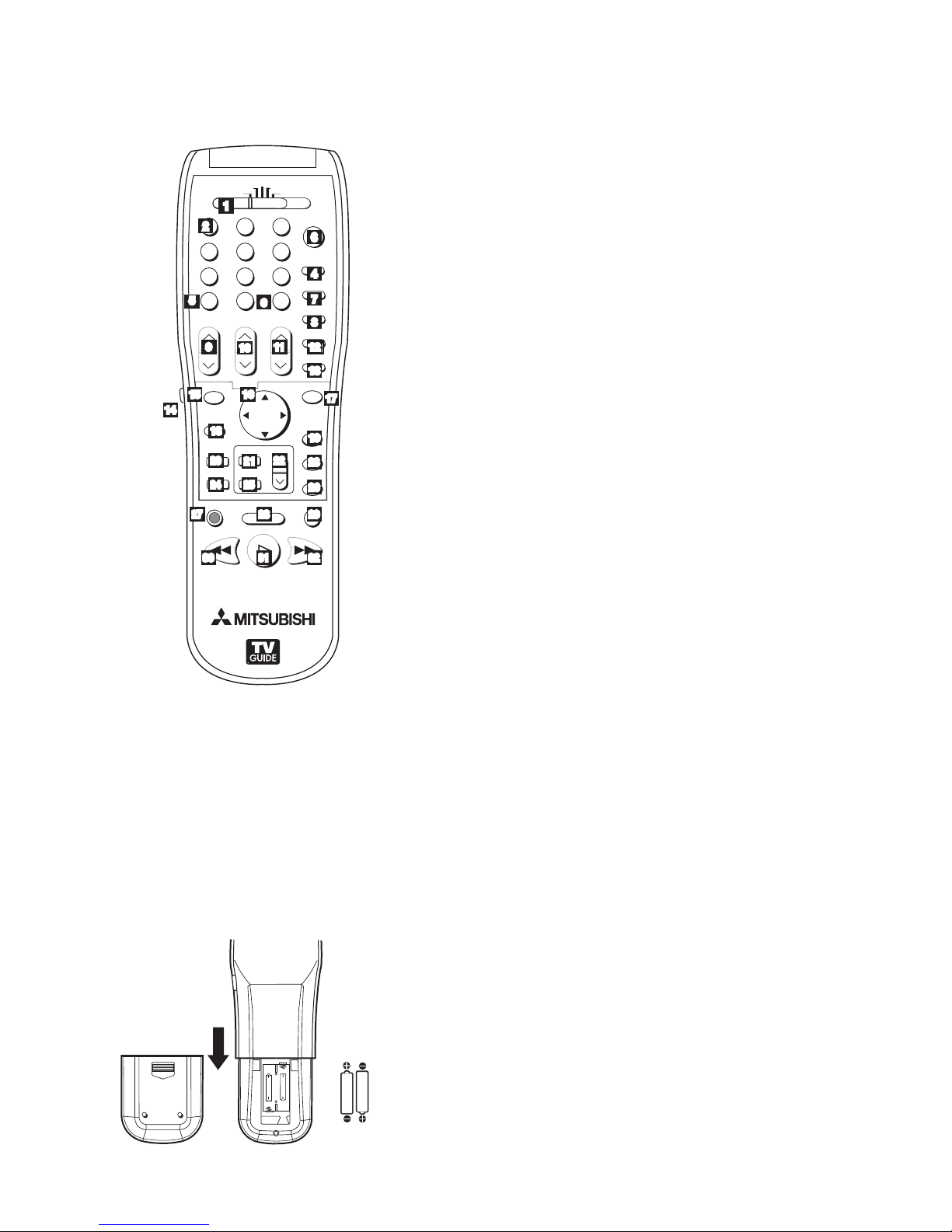
Remote Control
Overview
Figure 1, following page
1. Slide Switch: Selects A/V product to be controlled
by the remote control. Select TV for NetCommand®
device control.
2. Numbers: Individually select channels or enter
information into menus.
3. POWER: Turns power on and off for TV and other
A/V products.
4. GUIDE: Displays or removes TV Guide On Screen or
ChannelView for ANT-1 and 2. Displays Track List for
A/V Disc. Displays program guide for satellite receiver,
or DVD Disc menu. Displays thumbnails or play lists
for media card files.
5. SQV (SuperQuickView™): Scans through
memorized lists of favorite channels.
6. QV (QuickView™): Switches between the current
channel and last channel viewed.
7. SLEEP: Sets the TV to turn off within 2 hours. See
next page for setup instructions.
8. VIDEO: Selects and adjusts individual video settings.
9. DEVICE: Displays the Device Selection menu to
select the device to view (ANT-1 and ANT-2, or
devices connected to the TV’s inputs, including IEEE
1394 devices).
10. CH(ANNEL)/PAGE: Scans up or down through
memorized channels. When used with TV Guide
On Screen® and ChannelView, pages up and down
through screens.
11. VOLUME: Changes sound level.
12. AUDIO: Selects and adjusts individual audio settings.
13. MUTE: Turns sound on or off.
14. Light: Located on the left side of the remote control,
this feature illuminates buttons or labels.
15. ENTER/EXCH: Selects a channel number or menu
item. Exchange PIP and main TV picture. If PIP is
displayed, it must be cancelled before using the on-
screen menus for devices.
16. ADJUST: Press to navigate TV Guide On
Screen, menus, change settings, and move the PIP
on-screen location. Operates many NetCommand
functions.
17. SUB/CANCEL: Clears SQV and some menu entries
and cancels recordings. For digital channels, adds
separator between major and sub channel numbers.
18. TV MENU: Displays on-screen menu system.
19. DEVICE MENU: Displays or removes the options menu
for TV Guide On Screen. Displays the menu for devices
connected to the TV, including CableCARD™. For VCR
or DVDs, the first press displays the transport menu, the
second press displays the VCR or DVD menu.
20. V-CHIP: Turns On or Off the V-Chip Lock.
21. PIP: Turns on PIP and cycles through PIP display
choices.
22. PIP CH: Scrolls up or down through memorized
channels for PIP
23. HOME: Exits TV on-screen menus and the TV Guide
On Screen system and returns to TV viewing.
24. FORMAT: Changes the shape and size of the main TV
picture.
25. PIP DEVICE: Displays PIP Selection menu to select
the PIP image source device
26. INFO: First press displays an on-screen summary
of the current device used and any broadcast
information available (including current V-Chip
information). See Appendix D for details. While in the
TV Guide On Screen system, press the info button to
cycle through the available info box sizes.
27. REC (Record)/CONNECT: Displays the Record
menu for setting up recordings. Records with a VCR,
sets up recordings for DVCR, IEEE 1394 devices, or
while in ChannelView. When Listings screen for TV
Guide On Screen is displayed, will start a recording.
CONNECT: Initiates IEEE 1394 peer-to-peer
connections.
28. STOP: Stops a VCR, DVD, A/V Disc or media card file.
29. PAUSE: Pauses a live TV picture when no PIP image is
displayed. When PIP image is visible, pauses that image.
Pauses a VCR, DVD or A/V Disc, media card file.
30. REW/REV: Rewinds a VCR. Reverses scan with a DVD,
A/V Disc or media card file.
31. PLAY: Plays a VCR, DVD, A/V Disc or media card file.
32. FF/FWD: Fast forward a VCR or media card file, or fast
play a DVD.
Chapter 1. Television Overview 15
Remote Control, continued
108&3
)0.&
1"64&
3&$
'''8%3&83&7 1-":
4501
27
70-6.&
*/'0
&9$)
&/5&3
57.&/6 %&7*$&
.&/6
7$)*1
'03."5
1*1$)
427
%&7*$&
4-&&1
7*%&0
"6%*0
.65&
$)"//&-
"%+645
1*1
1*1%&7*$&
$"/$&-
57 "6%*0
$"#-&%#4%57 %7%
7$3
(6*%&
46#
$0//&$5
1"(&
12
2
3
4
5
6 7
9 10 11
8
13
14
15 16 17
18 19
20
21
22 23
25
27 29
3130
28
26
24
1
32
12
Figure 1. Remote Control Overview
Battery Installation
Figure 2
Installing the Batteries:
1. Remove the remote control’s back cover by gently
pressing the ribbed tab in the direction of the arrow
and sliding off the cover.
2. Load the batteries, making sure the polarities (+) and
(-) are correct. For best results, insert the negative (-)
side first.
"""BMLBMJOF
CBUUFSJFT
" " "
" " "
Figure 2. Operation: Installing the Batteries
Care
For Best Results from the Remote Control:
• Be within 20 feet of the equipment.
• Do not press two or more buttons at the same time
unless instructed.
• Do not allow unit to get wet or become heated.
• Avoid dropping on hard surfaces.
• Do not use harsh chemicals to clean. Use only a soft,
lightly moistened cloth.
• Do not mix new and old batteries.
• Do not heat, take apart or throw batteries into fire.
• Use only AAA alkaline batteries.
Hint: If the remote is in the TV layer and does
not function, press POWER and 935 to reset the
remote.
Sleep Timer
Setting the Sleep Timer:
1. Press SLEEP on the remote control.
2. Each additional press of SLEEP increases the time
displayed by 30 minutes, until the maximum value of
120 minutes is reached.
3. After 5 seconds of inactivity, the message will
disappear.
4. Press SLEEP to view the remaining time before the
timer turns the TV off.
Cancelling the Sleep Timer:
1. Press SLEEP to display the on-screen message.
2. Press SLEEP repeatedly until OFF is displayed.
Note: After 5 seconds of inactivity, the message
box disappears.
16 Chapter 1. Television Overview
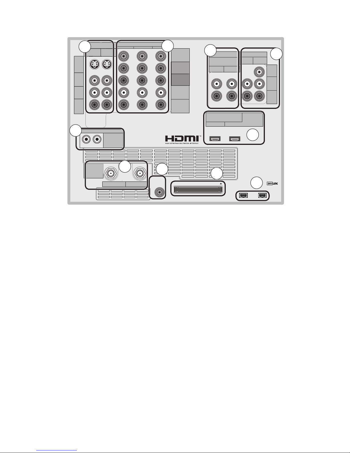
COMPONENT
YPbPr (480i/480p/720p/1080i)
INPUT
12
S-VIDEO
VIDEO
AUDIO-
LEFT/
(MONO)
AUDIO-
RIGHT
DTV/CABLE/
VHF/UHF
ANT 1 / MAIN ANT 2 / AUX
DIGITAL
AUDIO
OUTPUT CableCARD™ USE WITH ANT 1 CARD TOP
12
Y
Pb
Pr
AUDIO-
LEFT/
(MONO)
AUDIO-
RIGHT
OUTPUT
AUDIO
OUTPUT
RECORD
OUTPUT
DVI
Analog Audio
12VIDEO
AUDIO-
LEFT/
(MONO)
AUDIO-
RIGHT
MONITORLINK™/HDMI
VIDEO 480i/480p/720p/1080i
AUDIO PCM LINEAR
12
IEEE 1394
INPUT/
OUTPUT
Net Command
IR EMITTER
¸
',INK¸
INPUT
PC - 60Hz
VGA, W-VGA,
SVGA, W-SVGA,
XGA, 1280 X 720
TV Back Panel
1. Antenna (ANT-1 MAIN, ANT-2 AUX)
ANT-1 MAIN and ANT-2 AUX can each receive both digital
and analog over-the-air channels from a VHF/UHF antenna
or non-scrambled digital/analog cable source.
Your primary viewing signal source should be connected
to ANT-1 MAIN. ANT-1 MAIN must be used to view
premium subscription cable TV service authorized by the
CableCARD™ access card. The CableCARD access card
is provided by your local cable company. ANT-2 AUX can
receive over-the-air or non-scrambled cable signals.
2. IR EMITTER NetCommand®
IR Emitters connected to these jacks are used by the
NetCommand system of the TV to control external analog
devices such as cable boxes, VCRs, DVDs, satellite
receivers and audio receivers. This system is also
coordinated with the TV Guide On Screen® system for
the control of cable boxes and to activate the record
feature of your VCR. Either connection can be used for
NetCommand functions.
3. INPUT 1 and 2
(Audio/Video 1 and 2)
Inputs 1 and 2 can be used for the connection of a
VCR, Super VHS (S-VHS) VCR, DVD player, standard
satellite receiver or other A/V device to the TV. Please
note that if S-VIDEO and VIDEO are available for the
input, you must choose to connect only one. They
cannot both be connected at the same time.
4. COMPONENT 1, 2, and 3 Inputs
YPbPr (480i/480p/720p/1080i)
These inputs can be used for the connection of devices
with component video outputs, such as a DVD player,
external HDTV receiver, or compatible video game
system. Please see Appendix B for signal compatibility.
5. DVI Analog Audio
Unlike HDMI, DVI does not carry audio information on
the same cable. Use these analog stereo audio inputs
when using the HDMI input with a device that outputs
DVI instead of HDMI, such as DVI output from a personal
computer.
6. AUDIO OUTPUT, RECORD OUTPUT
AUDIO OUTPUT sends analog audio of the program
currently shown on the screen to an A/V surround sound
receiver or stereo system. Digital audio from digital
channels, FireWire® (DTV Link/IEEE 1394) devices and
HDMI devices is converted to analog audio by the TV. If
you do not have a digital A/V receiver, this should be the
only audio connection between the TV and your analog
A/V receiver or stereo system.
RECORD OUTPUT sends analog audio and video to a
VCR for recording purposes. These signals may not be
the same as those of the program that is currently being
shown on screen. Signals from digital channels and
FireWire (IEEE 1394) devices are converted to analog
signals. There is no video signal when copy restrictions
10
1
2
345
9
8
7
6

Chapter 1. Television Overview 17
TV Back Panel, continued
are in effect. Audio alone is output when Component 1, 2,
or 3, or the HDMI input is selected for recording.
7. HDMI™ 1 and 2
The HDMI (High Definition Multimedia Interface)
supports uncompressed standard and high-definition
digital video formats and PCM digital audio format.
Use these inputs to connect to EIA/CEA-861 compliant
devices such as a high-definition receiver or DVD player.
These inputs support 480i, 480p, 720p and 1080i video
formats.
These inputs can also be used as a DVI connection with
separate analog audio inputs. An optional HDMI-to-DVI
adaptor or cable is necessary to make this connection
and may be available from your local electronics retailer.
When using the optional HDMI-to-DVI adapter, the DVI
analog audio inputs on your TV allow you to receive left
and right audio from your DVI device.
This input is HDCP (High-Bandwidth Digital Copy
Protection) compliant.
HDMI 2
HDMI 2 also allows the TV to display DVI or HDMI output
from a PC. To view PC video on the TV, you must activate
the PC option in NetCommand. You can do this during
initial NetCommand setup (in the Device Setup screen),
or at any time afterwards by using the NetCommand Add
function.
If you want audio from a PC when using PC DVI output,
you must connect the PC audio output to the TV INPUT/
DVI Analog Audio 2, located above the HDMI 2 input.
8. DTV Link™/IEEE 1394
These jacks allow the TV to connect to external IEEE 1394
digital products by means of a single cable. Two jacks
are provided for this purpose, which allow for a high
degree of flexibility for connecting your NetCommand
controlled system. Detailed information regarding IEEE
1394 connection requirements are in Chapter 4.
9. CableCARD™ Slot
The CableCARD access card from your cable TV service
provider is inserted into this slot. The top of the card
should face in the direction indicated by CARD TOP .
CableCARD is a nationwide standard system that allows
your local cable TV provider to supply you with an
access card customized to your account. This card
allows the TV to receive, decode and unscramble the
premium digital channels included in your cable TV
subscription without the use of a cable box. See page
23 for additional CableCARD information and activation
instructions.
If your cable company is not currently offering
CableCARD access cards, you will need to use a
cable box provided and authorized by your local cable
company to view scrambled channels.
10. Digital Audio Output
This output sends Dolby® Digital or PCM digital audio to
your digital A/V surround sound receiver. Analog audio
from analog channels and devices is converted by the
TV to PCM digital audio. In most cases, this should be
the only audio connection between the TV and your A/V
receiver. If you have MP3 audio sources, however, you
need to connect the TV’s analog AUDIO OUTPUT (left
and right) to your A/V receiver.

18 Chapter 1. Television Overview
Front-Panel Input 3
These jacks allow for convenient connection of audio/
video devices to the front of the TV. Use the Input 3
jacks to connect a camcorder or other audio/video
device. Please note that if you connect to the S-VIDEO
terminal, the VIDEO terminal is deactivated. The
VIDEO terminal is active only when there is no S-Video
connection.
Media Card Slots and Front-Panel Inputs
Media Card Slots
To access the media card slots, press on the center
panel labelled PUSH. There are four card slots in the
front of the TV that allow the display of JPEG pictures
from many digital cameras, MP3 or WMA audio files
recorded from computers or other digital recording
devices.
The card slots are designed for the specific types of
cards listed below. Other cards or objects should
not be inserted into the slots as this may damage the
TV. See media card (slide show, play list) Setup for
details about JPEG, MP3 and WMA file types that are
compatible with the TV.
Card Compatibility
Slot Card Types
CARD 1 SmartMedia™
CARD 2 MultiMediaCard™
Secure Digital (SD)
CARD 3
CompactFlash®,
Types I and II
Microdrive®
CARD 4 Memory Stick PRO™
Memory Stick™
Portions of the advanced circuitry of this TV must continue to operate even when the
TV is turned off. Some of these circuits therefore need to be cooled at all times. A low-
power standby fan may be heard in a quiet environment. This is normal operation.
IMPORTANT
Memory
Card Reader Input 3
$"3%4NBSU.FEJB
5.
$"3% $PNQBDU'MBTI¥
.JDSP%SJWF¥
$"3%130
5.
%*%#4
$"3% .VMUJNFEJB$BSE
5.
4%$BSE
Card slots
36)$%/
).054 6)$%/ ,!5$)/2
Input 3 on front panel

Chapter 1. Television Overview 19
Additional Information
Do not attempt to update the software of this TV with software or cards that are not provided
by or authorized by Mitsubishi Digital Electronics America, Inc. Non-authorized software may
damage the TV and will not be covered by the warranty.
IMPORTANT
Demo Mode
This TV has a demo mode for use in retail stores. To turn the demo mode On/Off, press the following buttons in
sequence:
MENU, 0, QV, 0
Using the System Reset Button
If the TV doesn’t respond to either the remote control
or the front panel controls or will not power off, press
the SYSTEM RESET button on the front panel with a
pointed item such as the point of a ball point pen or
end tip of a paperclip.
The TV will turn off and the green LED will flash
quickly for about one minute. When the green LED
stops flashing, you may turn on the TV again. The
changes you made while the TV was most recently
on, before you used the SYSTEM RESET button may
be lost; the changes you made previously, however,
are not lost. Only those changes since the last power
On may be lost when the system reset button is
pressed. All other settings are retained.
Using the Reset Menu to Reset the
TV
Read on-screen warnings before
proceeding, as some user data or
settings may be erased.
1. Select any device from the Device Selection
menu. Press TV MENU followed by 1,2,3 to see
the RESET SERVICE MENU to reset the TV.
2. Select Reset System Defaults (CAUTION: All
settings, except V-Chip, will be reset to the
original factory defaults).

Other manuals for HL-2600CN Series
5
This manual suits for next models
2
Table of contents


