BRP Can-Am Spyder RS 2014 Series Manual

ROADSTER
PREDELIVERY
Bulletin
October 09, 2013 Subject:Can-Am™ Spyder™ RS Predelivery
Inspection
No. 2014-2
YEAR MODEL MODEL NUMBER SERIAL NUMBER
2014 Spyder RS Series Refer to table on next
pages for complete listing All
TABLE OF CONTENTS
Page Page
IMPORTANT NOTICE ....................... 2
UPDATE SUMMARY........................ 3
MODEL LISTING............................. 3
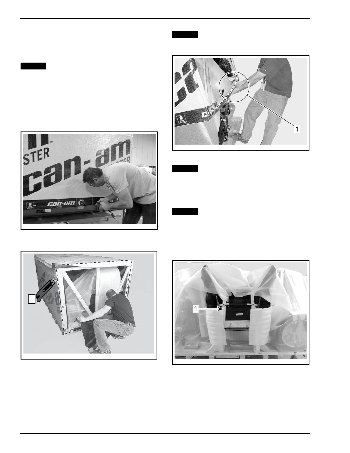
UNCRATING.................................. 4
Crate Cover Removal .......................... 4
Parts and Sub-crate Removal ................. 4
Parts Check...................................... 5
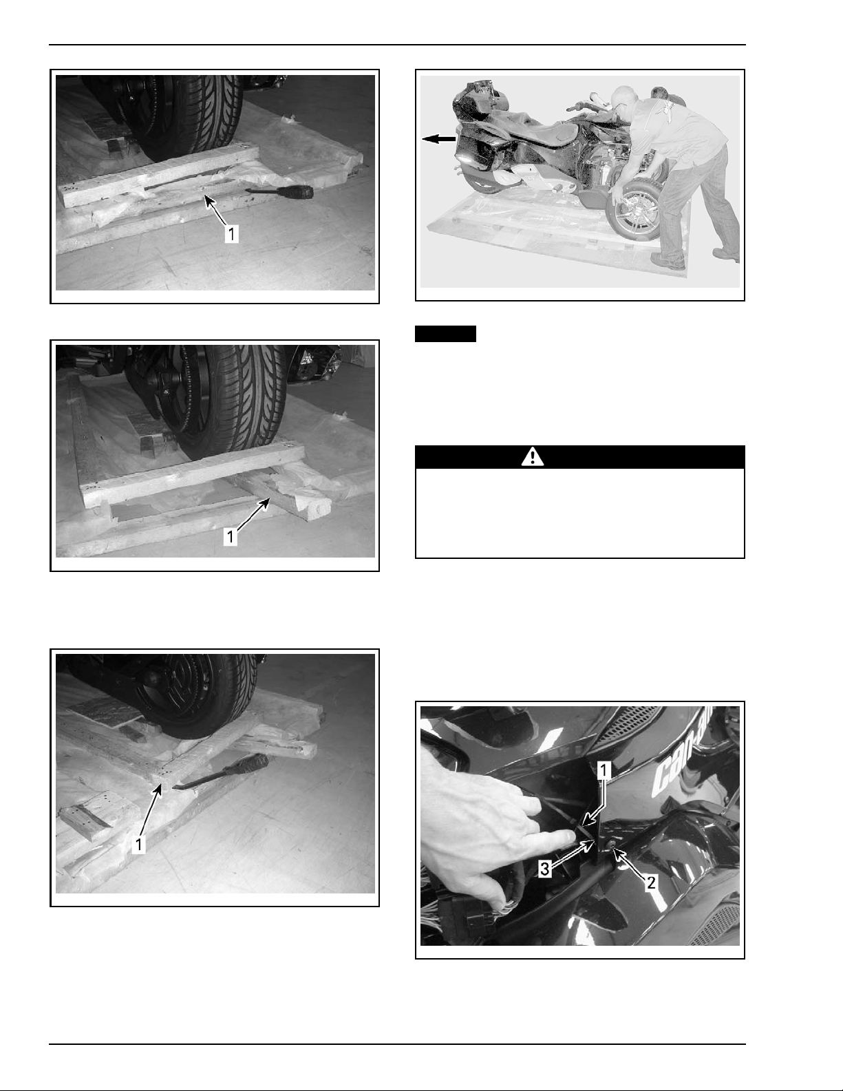
Lifting the Front of Vehicle ................... 6
Front Wheels Installation ...................... 8
Vehicle Removal ................................ 9
PARTS TO BE INSTALLED................. 10
Front Cargo Module .. .... .... .... .... .... .... .. 10
Battery ........................................... 13
AAPTS (Ambient Air Pressure and Temperature
Sensor) Installation ............................. 15
Low Beam Headlight Connection ............ 15
Horn Connection................................ 15
Latch Release Cable, Front Storage
Compartment Cover ........................... 16
Diagnostic Link Cable (DLC) .................. 16
Body Parts Installation ......................... 16
Front Fenders ................................... 18
Rear Fender ..................................... 20
Hang Tag and Safety Labels .................. 22
Licence Plate Installation ...................... 22
Accessories Installation........................ 23
Vehicle Decals................................... 23
FLUIDS......................................... 23
General Guidelines ............................. 23
Fuel............................................... 23
Clutch Fluid (SM5 Model) ..................... 24
Engine Coolant.................................. 24
Brake Fluid....................................... 25
Engine Oil........................................ 26
SETUP ......................................... 29
Guidelines ....................................... 29
Tire Pressure .................................... 29
Drive Belt ........................................ 29
Clutch Lever..................................... 30
Lights............................................. 30
B.U.D.S. Programming......................... 32
Cluster Units and Clock Setting (Base
Model)............................................ 35
Clock and Language Setting (All Except Base
Model)............................................ 36
ASSEMBLY INSPECTION.................. 37
FINAL INSPECTION ......................... 37
Vehicle Test Run................................ 37
Vehicle Cleaning ................................ 38
Delivery to Customer .......................... 38
Printed in Canada. (rbl2014-002 en JL)
©2013 Bombardier Recreational Products Inc. and BRP US Inc. All rights reserved. 1/39
®™ and the BRP logo are trademarks of Bombardier Recreational Products Inc. or its affiliates.

IMPORTANT NOTICE
IMPORTANT NOTICE
This bulletin must be used in conjunction with the check list enclosed in the bag with the
OPERATOR’S
GUIDE
. Make sure that Spyder roadster
PRE DELIVERY CHECK LIST
is completed and signed.
WARNING
To obtain warranty coverage, predelivery procedures must be performed by an authorized BRP
Can-Am roadster dealer/distributor. Apply all necessary torques as indicated.
NOTE: The information and components/system descriptions contained in this document are correct at
the time of publication. BRP however, maintains a policy of continuous improvement of its products with-
out imposing upon itself any obligation to install them on products previously manufactured.
Due to late changes, there might be some differences between the manufactured product and the de-
scriptions and/or specifications in this document. BRP reserves the right at any time to discontinue or
change specifications, designs, features, models or equipment without incurring obligation.
The illustrations in this document show the typical construction of the different assemblies and may not
reproduce the full detail or exact shape of the parts. However, they represent parts that have the same
or similar function.
The content of this bulletin is designed as a guideline only. All mechanics performing predelivery
procedures should have attended the current model-year service training.
Further information or inquiries should be directed to your service representative and specific
SHOP MANUAL
sections.
Make sure the customer receives the
OPERATOR’S GUIDE
,
PREDELIVERY CHECK LIST
signed copy
and
SAFETY DVD
.
WARNING
Torque wrench tightening specifications must be strictly adhered to. Where specified, install new
locking devices (e.g. lock tabs, elastic stop nuts). If the efficiency of a locking device is impaired,
it must be renewed.
2 / 39 2014-2 PREDELIVERY

MODEL LISTING
UPDATE SUMMARY
This summary highlights updates to the Predelivery Inspection for MY2014. It does not supersede pro-
cedures detailed further in this publication.
IMPORTANT: Technicians should read and apply all procedures in this PDI bulletin as applicable to model.
APPLICABLE TO UPDATE DESCRIPTION REFERENCE
Uncrating method sequence modified
UNCRATING
Front cargo module installation sequence
additions, modifications and sequence changes
PARTSTOBEINSTALLED
Body parts installation sequence additions and
modifications.
PARTSTOBEINSTALLED
New front and side panels (all except Brazil
models)
PARTSTOBEINSTALLED
RS Models
NEW engine coolant
FLUIDS
MODEL LISTING
YEAR MODEL MODEL
NUMBER COUNTRY PREDELIVERY KIT SERIAL
NUMBER
A1EE Australia (P/N 703 100 428)
A1EF Brazil (P/N 703 100 385)
A1EB, A1EC,
A1EG, A1EH
Canada
United States of America
Spyder RS SM5
A1ED Europe
(P/N 703 100 428)
A2EE Brazil (P/N 703 100 385)
A2EB, A2EC,
A2EF, A2EG
Canada
United States of America
Spyder RS SE5
A2ED, A2EH Europe
(P/N 703 100 428)
B6EB, B6EC,
B6ED, B6EE,
B6EG, B6EH
Canada
United States of America
Spyder RS-S SM5
B6EF Europe
B1EE, B1EK Australia
(P/N 703 100 431)
B1EF, B1EP Brazil (P/N 703 100 400)
B1EB, B1EC,
B1EG, B1EH,
B1EL, B1EM
Canada
United States of America
2014
Spyder RS-S SE5
B1ED, B1EJ,
B1EN Europe
(P/N 703 100 431)
All
PREDELIVERY 2014-2 3 / 39

UNCRATING
UNCRATING
Crate Cover Removal
NOTICE Allowing the crate to drop may cause
serious damage to vehicle.
1. Position the crate on a firm, level surface.
2. Remove all screws holding crate cover to crate
base.
NOTE: Screws that are used are Robertson†#2
type (or equivalent) that require the use of an ap-
propriate screwdriver.
rbl2014-004-026
SCREW REMOVAL FROM CRATE COVER
3. Carefully cut both ends of crate tarpaulin.
1
rbl2014-004-001_a
1. Carefully cut both ends of crate tarpaulin
4. Locate front of vehicle
5. At front end of vehicle, pull crate cover out to-
ward you, then up to clear vehicle fascia.
NOTICE Do not lift crate cover vertically. Pull
crate cover out and up at front end of vehicle.
Refer to illustration.
rbl2010-002-004_a
FRONT OF VEHICLE
1. Pull crate cover out and up to clear front fascia of the vehicle
NOTICE The crate cover must be pulled out-
ward while lifting it to avoid damage to the ve-
hicle.
Parts and Sub-crate Removal
NOTICE Be careful not to scratch the front
bumper and front fascia.
NOTE: The sub-crates are located on each side of
the vehicle.
1. On LH side, remove front cargo module sub-
crate.
rbl2014-004-027_a
TYPICAL - LH SIDE
1. Sub-crate that contains front cargo module
† Robertson is a registered trademark of Robertson Inc.
4 / 39 2014-2 PREDELIVERY

UNCRATING
rbl2014-004-028_a
SCREWS TO REMOVE, BOTH SIDES OF CARGO MODULE
SUB-CRATE
2. Remove protective foam from vehicle.
rbl2010-002-005
3. Remove front wheels from crate base.
rbl2013-003-001_b
TYPICAL
1. Front wheels
4. On RH side, remove shipping covers from fend-
ers.
5. Remove two fenders from sub-crate.
rbs2011-014-002_a
TYPICAL - RH SIDE - SUB-CRATE THAT CONTAINS FRONT
FENDER
1. Bolts to remove (6)
6. Remove fender sub-crate.
rbl2014-004-002
TYPICAL - FRONT FENDER SUB-CRATE REMOVAL
7. If you dot not have a fully charged new bat-
tery of the same type on hand, remove bat-
tery from vehicle and carry out the
BATTERY
CHARGING
procedure. See
BATTERY
further
in this bulletin.
Parts Check
Ensure the crate includes the following items
(inside front storage compartment or secured to
front of vehicle).
PREDELIVERY 2014-2 5 / 39

UNCRATING
FRONT STORAGE COMPARTEMENT
DESCRIPTION MODEL QTY
Operator's
guide 1
Predelivery
check list 1
Safety DVD 1
Predelivery kit 1
Service cover 1
Wheel caps 2
Fender
reinforcement
brackets
All
2
Ensure predelivery kit includes the following
items.
PREDELIVERY KIT
DESCRIPTION WHERE USED QTY
Wheel lug nut - chrome
(RS) Front wheels 6
Wheel lug nut - black (RS-S) Front wheels 6
M6 X 20 hexagonal flanged
forming screw
Front cargo
module 4
M6 X 12 hexagonal flange
screw
Front cargo
module 2
M6 panel nut Body panels 2
M6 panel nut
(All models except Brazil) Body panels 4
M6 x 20 Torx screw Body panels 4
Plastic washer Body panels 2
Plastic washer
(All models except Brazil) Body panels 4
M8 x 20 hexagonal flange
screw Front fenders 8
M6 x 12 hexagonal flange
screw (reinforcement) Rear fender 4
Locking tie Rear fender 4
M6 X 20 Torx screw Rear fender 4
M6 X 16 Torx screw
(reinforcement) Rear fender 4
Plastic washer Rear fender 4
PREDELIVERY KIT
DESCRIPTION WHERE USED QTY
M6 elastic flange nut Rear fender 4
M6 elastic flange nut
(reinforcement) Rear fender 4
Battery installation kit (2
bolts and 2 nuts)
Battery
terminals 1
Lifting the Front of Vehicle
WARNING
No one should be standing in front or at the
back of the vehicle while straps are being cut.
1. Remove metal plate retaining front of vehicle to
crate base.
NOTE: If you are planning to use a hoist to lift ve-
hicle from crate base for tire installation, only the
wood screws need to be removed at this time.
rbl2013-003-002_a
1. Plate
2. Screws
3. Screw and nuts
2. Remove straps retaining side and front of vehi-
cle to crate base.
6 / 39 2014-2 PREDELIVERY

UNCRATING
rbl2010-002-011_a
TYPICAL
1. Side strap
rbl2014-004-032a
LH FRONT ILLUSTRATED
1. Front strap, each side
NOTE: The steps to follow are describes using
two methods for lifting the front of the vehicle
from the crate base. The conventional method
uses a hydraulic jack and the alternate method
uses a chain block. Use the proper method ac-
cording to your shop layout.
Conventional Method
1. Remove piece of wood located at the front of
the vehicle.
NOTE: This piece of wood can be used to level the
jack.
rbl2013-003-003_a
TYPICAL
1. Wood piece to remove
2. Install a floor jack with a piece of wood on top
to increase contact surface of jack pad.
rbl2013-003-004_a
TYPICAL-FRONTOFVEHICLE
1. Jack
2. Wood piece
3. Wood piece removed earlier
CAUTION Approach with care when vehi-
cle is jacked because it may be unstable.
3. Lift the vehicle.
PREDELIVERY 2014-2 7 / 39

UNCRATING
rbl2010-002-016
TYPICAL
NOTICE Never lift vehicle by the suspension
arm.
Alternate Method
1. Install proper straps with hooks on RH and LH
lateral supports of vehicle.
NOTE: Insert hooks through the holes in the
frame.
rbl2013-003-005_a
TYPICAL
1. Strap
2. Hook
3. Frame
2. Hook straps on an appropriate lifting kit.
3. Lift vehicle using a chain block.
NOTICE Never lift vehicle by the suspension
arm.
Front Wheels Installation
1. Clean front and rear brake discs.
NOTICE A thin layer of anticorrosion treat-
ment is present on the brake discs and must
be removed before using the vehicle. Not con-
forming to this procedure may lead to a brake
chattering squeaking and brake pad replace-
ment would be necessary.
BRAKE DISC CLEANING
SERVICE PRODUCT REQUIRED TOOL
XPS BRAKES AND
PARTS CLEANER (CAN)
(P/N 219 701 776)
XPS BRAKES AND
PARTS CLEANER (USA)
(P/N 219 701 705)
Shop rag
NOTE: An equivalent brakes and parts cleaner that
is respectful of all laws and regulations in your
area may be used.
2. Remove nut securing front brake discs to vehi-
cle.
rbl2013-003-006_a
TYPICAL
1. Nut to remove, both sides
3. Install front wheels on vehicle.
NOTE: Ensure that the rotation direction shown by
the arrow on the tire is respected.
WARNING
The tires are only designed to rotate in one di-
rection. Do not switch the left and right front
wheels.
4. Hand tighten wheel lug nuts snug (from PDI kit).
5. Lower vehicle on crate base.
6. Remove the floor jack (or hoist and lifting strap).
8 / 39 2014-2 PREDELIVERY

UNCRATING
rbl2013-003-007
TYPICAL
7. Torque wheels lug nuts.
PART SPECIFIED TORQUE
Wheel lug nut 105 N•m (77 lbf•ft)
8. Install wheel caps (inside front storage com-
partment).
rbl2014-004-033_a
TYPICAL
1. Front wheel cap to install, one each side
9. Remove metal plate that retained front of vehi-
cle to crate base.
NOTE: This step is only applicable if a hoist was
used to lift front of vehicle from crate base for tire
installation.
rbl2014-002-001_a
1. Metal plate to remove
2. Screws to remove
Vehicle Removal
NOTE: Parking brake pedal brakes only the rear
wheel. Press the pedal down to apply the parking
brake. Press the pedal down again to remove it.
The parking brake pedal is behind the operator's
left footpeg.
NOTICE Do not apply excessive force when
applying or removing the parking brake.
1. Place a piece of wood behind the front wheels
to prevent the vehicle from rolling.
rbl2013-003-008_a
TYPICAL - FRONT RH WHEEL
1. Wood piece
2. Remove the piece of wood at the back of the
crate and insert it under the rear wheel.
PREDELIVERY 2014-2 9 / 39

PARTS TO BE INSTALLED
rbl2013-003-009_a
TYPICAL
1. Wood piece
rbl2013-003-010_a
TYPICAL
1. Wood piece removed earlier
3. Remove the piece of wood from behind the rear
wheel.
rbl2013-003-011_a
TYPICAL
1. Wood piece behind rear wheel
4. Carefully remove pieces of wood positioned
earlier behind the front wheels.
5. With the help of your assistant, move vehicle
rearward out of the crate base.
rbl2010-002-021_a
TYPICAL
NOTICE Always move vehicle rearward out of
the crate base.
PARTS TO BE INSTALLED
Front Cargo Module
WARNING
Make sure battery is not connected before
installing front cargo module. Do not install
front cargo module if battery is connected
because sparks can occur if tools touch bat-
tery terminals.
1. Unlock and lift seat to full open position.
2. Remove LH and RH upper side panels.
2.1 Cut locking tie retaining upper side panel.
Remove panel nut and screw.
NOTE: Keep panel screws and nuts for instal-
lation further in procedure.
rbl2013-002-018_a
BRAZIL MODELS
1. Locking tie
2. Panel screw
3. Panel nut
10 / 39 2014-2 PREDELIVERY

PARTSTOBEINSTALLED
rbl2014-002-003_a
ALLEXCEPTBRAZILMODELS
1. Upper side panel
2. Panel screw
3. Panel nut
4. Locking tie
2.2 Remove screws at rear of panel.
rbl2013-002-019_a
TYPICAL - ALL MODELS
1. Screws to remove
2.3 Install the previously removed panel nut on
lateral bracket.
rbl2013-002-020_a
TYPICAL
1. Panel nut
3. Assisted by another person, remove and dis-
card bolts holding the bottom and the top sec-
tions of sub-crate.
rbl2014-002-002_a
TYPICAL
1. Lower retaining bolts
2. Upper retaining bolts
NOTE: Be careful not to lose the caged nuts lo-
cated in the bottom fixation holes of the front
cargo module.
4. Open front storage compartment cover.
5. Remove 3 plastic rivets securing LH and RH
front panels.
rbl2008-003-100_d
TYPICAL - FRONT PANEL PLASTIC RIVET LOCATIONS
6. Cut locking ties securing horn and AAPTS har-
ness to frame.
PREDELIVERY 2014-2 11 / 39

PARTS TO BE INSTALLED
7. Ensure the following cables and connectors are
accessible prior to installing front cargo module,
cut locking ties if required.
rbl2013-003-015_b
TYPICAL - REFER TO THE FOLLOWING TABLE FOR ITEMS
DESCRIPTION
ITEMS DESCRIPTION
1AAPTS sensor connector (hidden
on the illustration)
2Horn connector (hidden on
the illustration)
3Low beam headlight (CE)
4DLC connector (B.U.D.S.)
5Storage cover switch connector
(option package)
6Storage cover cable
712 V power outlet (option package)
8. Turn up and store cable and all the wiring and
connectors in the front of the vehicle to prevent
them from being pinched between the front
cargo module and front frame.
9. Before installing front cargo module, remove
the fuse box service covers as follows:
9.1 Push down on the fuse box service covers
to open and pull the covers off.
rmo2013-003-011_a
1. Left fuse box service cover
2. Right fuse box service cover
NOTE: Removal of fuse box service covers is
required only to aid in the alignment of the
front cargo module when installing it onto the
front frame of the vehicle.
9.2 Turn up and store all the wiring and con-
nectors on front cargo module to prevent
them from being pinched between the
cargo module and front frame.
10. Assisted by another person, position front
cargo module onto upper supports in the
front frame of the vehicle.
NOTE: Ensure that no cable or wiring was pinched
between cargo module and front frame prior to
installing any fastener.
rbl2014-004-045_a
TYPICAL
1. Front cargo module
2. LH upper support, RH similar
11. Secure the front cargo module using following
hardware.
– At the TOP, use four M6 x 20 hexagonal
flanged forming screws.
–Att
he bottom, use two M6 x 12 hexagonal
flange screws.
12 / 39 2014-2 PREDELIVERY

PARTSTOBEINSTALLED
NOTE: In following illustration, some panels were
removed for clarity
rbl2013-002-021_a
TOP SCREWS
1. M6 X 20 hexagonal flange screw locations
rbl2008-003-213_b
BOTTOM SCREWS
1. M6 X 12 hexagonal flange screw locations
NOTE: Install all screws before tightening them.
FRONT CARGO
MODULE SCREWS SPECIFIED TORQUE
M6 X 20 hexagonal
forming screws (4) 4.5 N•m (40 lbf•in)
M6 X 12 hexagonal
flange screws (2) 10 N•m (89 lbf•in)
12. Reinstall the fuse box service covers as fol-
lows:
12.1 Position the bottom of the fuse box ser-
vice cover and push down and in until
the top of the fuse box service cover en-
gages.
rmo2013-003-011_a
TYPICAL
1. Left fuse box service cover
2. Right fuse box service cover
Battery
Battery Activation
The battery is fully activated and only requires an
initial top up charge to ensure it is fully charged
prior to vehicle delivery.
NOTE: If you do not have a fully charged new bat-
tery at hand, the battery can be removed from the
vehicle, fully charged as per manufacturers spec-
ification and reinstalled in the vehicle later.
IMPORTANT: It is of the upmost importance for
the battery life span that the initial charging be
performed as recommended. Refer to the latest
CAN-AM ROADSTER BATTERY ACTIVATION,
CHARGING AND MAINTENANCE
. Correct key-
words to search the latest Service Bulletin in
BOSSWEB or Info Center are :"roadster battery
activation" including quotation marks.
Install charged battery in battery rack.
Battery Removal
The battery is located on the front frame member,
just aft of the front cargo module.
1. Pull down the rubber strap to disengage it from
the hook.
PREDELIVERY 2014-2 13 / 39

PARTS TO BE INSTALLED
rbl2013-003-012_a
TYPICAL
1. Battery
2. Rubber strap
3. Hook
2. Remove bracket and battery from the vehicle.
rbl2013-003-012_b
TYPICAL
1. Battery
2. Bracket
Battery Installation
1. If front storage module is installed, carry out the
following:
– Open front storage compartment cover.
–Unzip
storage compartment liner for access
to battery access panel.
– Remove battery access panel.
2. Insert battery in battery rack with battery posts
facing out.
NOTICE Always charge battery before its in-
stallation on the vehicle.
3. Connect RED (+) positive battery cables first us-
ing battery screws and square nutS from the
PDI kit.
WARNING
Always connect RED (+) cable first.
4. Connect BLACK (–) negative battery cables sec-
ond using battery screw and nut from the PDI
kit.
PART SPECIFIEDTORQUE
Battery post screws 4 N•m (35 lbf•in)
rbl2013-003-013_a
1. Battery
2. RED (+) positive battery cable
3. Positive post battery screw
5. Apply dielectric grease on battery posts.
SERVICE PRODUCT
Battery posts DIELECTRIC GREASE
(P/N 293 550 004)
6. Install RED rubber boot cover.
rbl2013-003-013_b
1. Battery
2. Black (-) negative battery cable
3. Negative post battery screw
4. RED rubber boot cover
14 / 39 2014-2 PREDELIVERY

PARTSTOBEINSTALLED
7. Position battery retaining bracket over battery.
Be sure to properly engage it in the frame front
member.
8. Install rubber retaining strap.
rbl2013-003-014_a
1. Battery
2. Retainingbracket
3. Rubber strap
4. Hook on lower front frame member
AAPTS (Ambient Air Pressure
and Temperature Sensor)
Installation
1. Connect AAPTS connector and route cable
through retaining guide clips (RH side of cargo
module).
rbl2013-002-003_a
1. Cable retaining clip
2. Connector
Low Beam Headlight
Connection
Models with Low Beam Headlights
Mounted in Cargo Module
1. Connect wiring harness to low beam head-
lights.
rbl2008-003-215_b
1. Low beam headlight connector
Horn Connection
1. Connect horn connector.
2. Route cable through the retaining guide clips
(LH side of cargo module).
rbl2013-002-007_a
1. Horn connector
Models with Low Beam Headlights
Mounted in Cargo Module
If necessary, remove horn from vehicle to ease
connector installation.
PREDELIVERY 2014-2 15 / 39

PARTS TO BE INSTALLED
rbl2009-001-003_a
TYPICAL - HORN RETAINING BOLT LOCATION
Latch Release Cable, Front
Storage Compartment Cover
1. Feed the latch release cable through the latch
base eyelet.
2. Attach latch release cable end to latch lever
tongs.
3. Using pliers, squeeze lever tongs together to
prevent cable from coming out of latch release
lever.
rbl2013-002-004
4. Verify if the front storage compartment cover
opens and closes correctly.
5. Adjust cable if necessary.
NOTICE If the key does not turn easily, do not
force it. Pull it out and reinsert.
Diagnostic Link Cable (DLC)
1. Insert diagnostic link cable (DLC) in its holder in
the front section of vehicle for storage.
rbl2013-002-005
DLC CABLE STORAGE
Body Parts Installation
NOTICE Do not overtighten screws. Any de-
formation in the body panel around the screw
is an indication that it is too tight. Be careful
not to damage the panels.
Front Panels
1. Install M6 panel nuts on front panels (included
in the PDI kit)
Brazil models
rbl2009-001-004_a
RH FRONT PANEL SHOWN, LH SIMILAR
1. Front M6 panel nuts
16 / 39 2014-2 PREDELIVERY

PARTSTOBEINSTALLED
All Except Brazil Models
rbl2014-002-006_a
LH FRONT PANEL SHOWN, RH SIMILAR
1. Front panel
2. Front M6 panel nuts
All Models
2. Install both front panels on vehicle using plastic
rivets removed earlier.
rbl2008-003-100_d
TYPICAL - FRONT PANEL PLASTIC RIVET LOCATION
3. Secure front panels to vehicle using screws re-
moved during front panel removal earlier.
NOTE: On models with low beam headlights in
cargo module, move side air deflector backward
for a better fit.
rbl2008-003-100_a
BRAZIL MODELS
1. Move side air deflector backward
2. Area that must be fit
3. Front panel screw
rbl2014-002-004_a
ALL EXCEPT BRAZIL MODELS
1. Front panel screw
Upper Side Panel Installation
Brazil Models
Position upper side panels on vehicle and install
screws illustrated.
rsi2008-013-003_a
TYPICAL - LH SIDE ILLUSTRATED
All Except Brazil Models
Insert front tabs of upper side panel in slots pro-
vided in front panel.
PREDELIVERY 2014-2 17 / 39

PARTS TO BE INSTALLED
rbl2014-002-005_a
1. Front panel
2. Slots for inserting front tabs of upper side panel
Install screw to secure front end of upper side
panel.
rbl2014-002-007_a
1. Upper side panel
2. Front panel
3. Screw to install
All Models
Close seat.
Service Cover
Install service cover on the front of vehicle (in-
cluded in front cargo module).
Close front storage compartment cover.
Front Fenders
NOTE: Fender installation similar on both sides.
1. Cut locking tie that hold harness bracket on
fender.
rbl2011-002-010_a
TYPICAL
1. Locking tie
2. Ensure proper position of fender wiring har-
ness.
NOTE: LH illustrated, RH similar.
rbl2014-004-048_a
1. Wiring harness clamps
2. Wiring harness bracket
NOTE: Do not remove protection from suspension
arms.
rbl2013-004-002_a
TYPICAL
3. Position front fender on vehicle.
18 / 39 2014-2 PREDELIVERY

PARTSTOBEINSTALLED
rbl2011-002-011
TYPICAL
4. Install 4 M8x 20 hexagonal flange screws
loosely to hold the fender in its position.
NOTE: Be sure to install the fender light harness
and ABS harness brackets as illustrated. Do not
torque screws at this time.
NOTE: Left side fender installation illustrated,
right side similar.
rbl2014-004-049_a
1. Fender light harness bracket, top screw, forward fender support
2. ABS harness bracket, lower screw, rear fender support
3. ABS sensor
5. Connect fender light connector.
NOTE: Make sure harnesses are properly secured
through cable grommet in upper suspension arm.
rbl2013-002-006_a
1. Fender light connector
rbl2013-002-009_a
1. Cable grommet
2. Harness bracket
6. Tighten fender support screws to specification.
rbl2013-002-008_b
1. M8 x 20 hexagonal flange screws
SPECIFIED TORQUE
Fender support retaining
screws 24 N•m (18 lbf•ft)
PREDELIVERY 2014-2 19 / 39

PARTS TO BE INSTALLED
7. Ensure harness brackets are properly posi-
tioned when torque is applied.
8. Ensure cap for wheel hub nut is properly se-
cured to steering knuckle.
rbl2014-004-050_a
TYPICAL
1. Check for harness bracket contact here
2. Wheel hub nut cap secure
9. Remove protection from suspension arms.
Rear Fender
NOTE: Before applying any torque, install all nuts
and screws.
1. Remove rear fender packaging.
2. Loosen LH and RH fender support screws.
rbl2013-002-012_a
LEFT SIDE FENDER SUPPORT
1. Screws, washers and nuts
3. Pre-assemble rear fender to its LH and RH rear
fender brackets with M6 x 12 screws, flat plas-
tic washers and M6 nuts (on back side).
rbl2013-002-013_a
1. Rear fender
2. Support
3. M6 x 12 Screws, washers and nuts
NOTE: Do not torque screws.
4. Connect license plate light connector.
5. Secure license plate light harness inside RH
rear fender support using 4 locking ties (from
PDI kit) into factory installed retainers.
rbl2013-002-010_a
1. License plate light harness
2. Rear fender support
3. Locking ties in retainers
20 / 39 2014-2 PREDELIVERY
This manual suits for next models
4
Table of contents
Other BRP Motorcycle manuals