BRP Can-Am Spyder RT 2013 Series User manual

ROADSTER
PREDELIVERY
Bulletin
November 16, 2012 Subject:Can-Am™ Spyder™ RT Predelivery
Instructions
No. 2013-2
REVISION 2
March 14th, 2013
YEAR MODEL MODEL NUMBER SERIAL NUMBER
2013 Spyder RT Series Refer to table on next
pages for complete listing All
Text(s) between arrows is (are) modified element(s) to the original publication.
TABLE OF CONTENTS
Page Page
IMPORTANT NOTICE ....................... 2
UPDATE SUMMARY........................ 3
MODEL LISTING............................. 3
UNCRATING.................................. 4
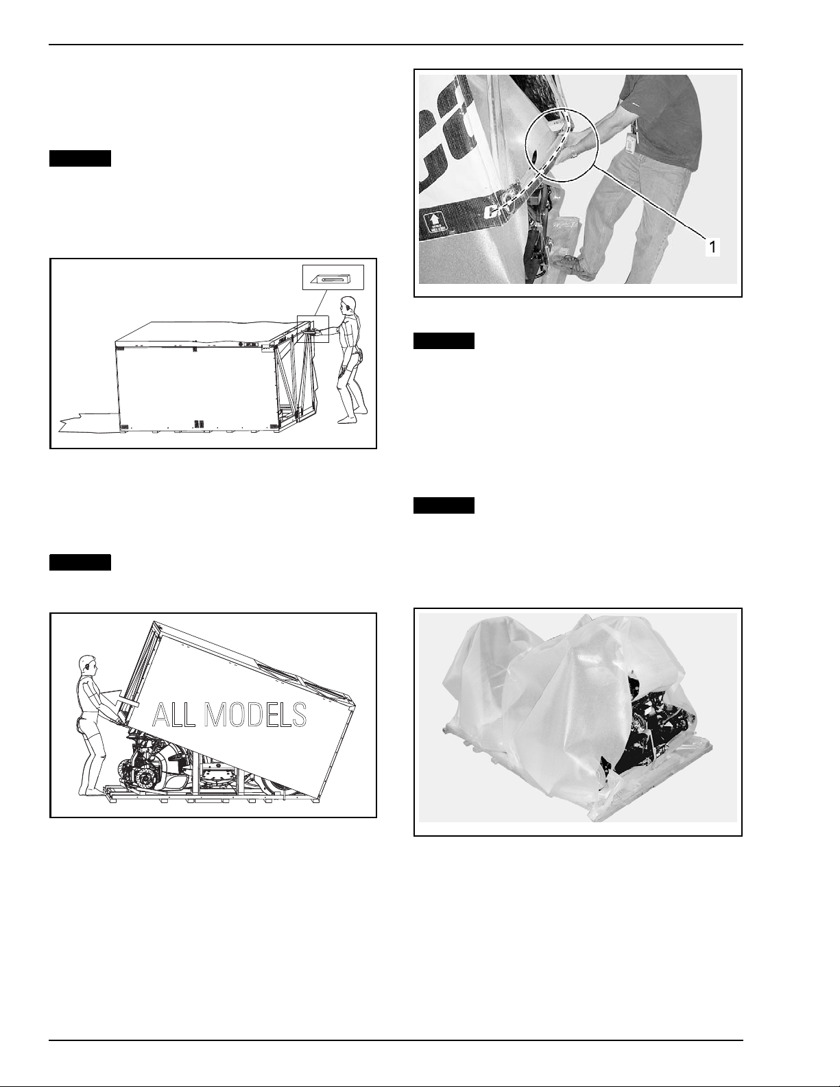
Crate Cover Removal .......................... 4
Parts and Sub-crates Removal................ 4
Parts Check...................................... 5
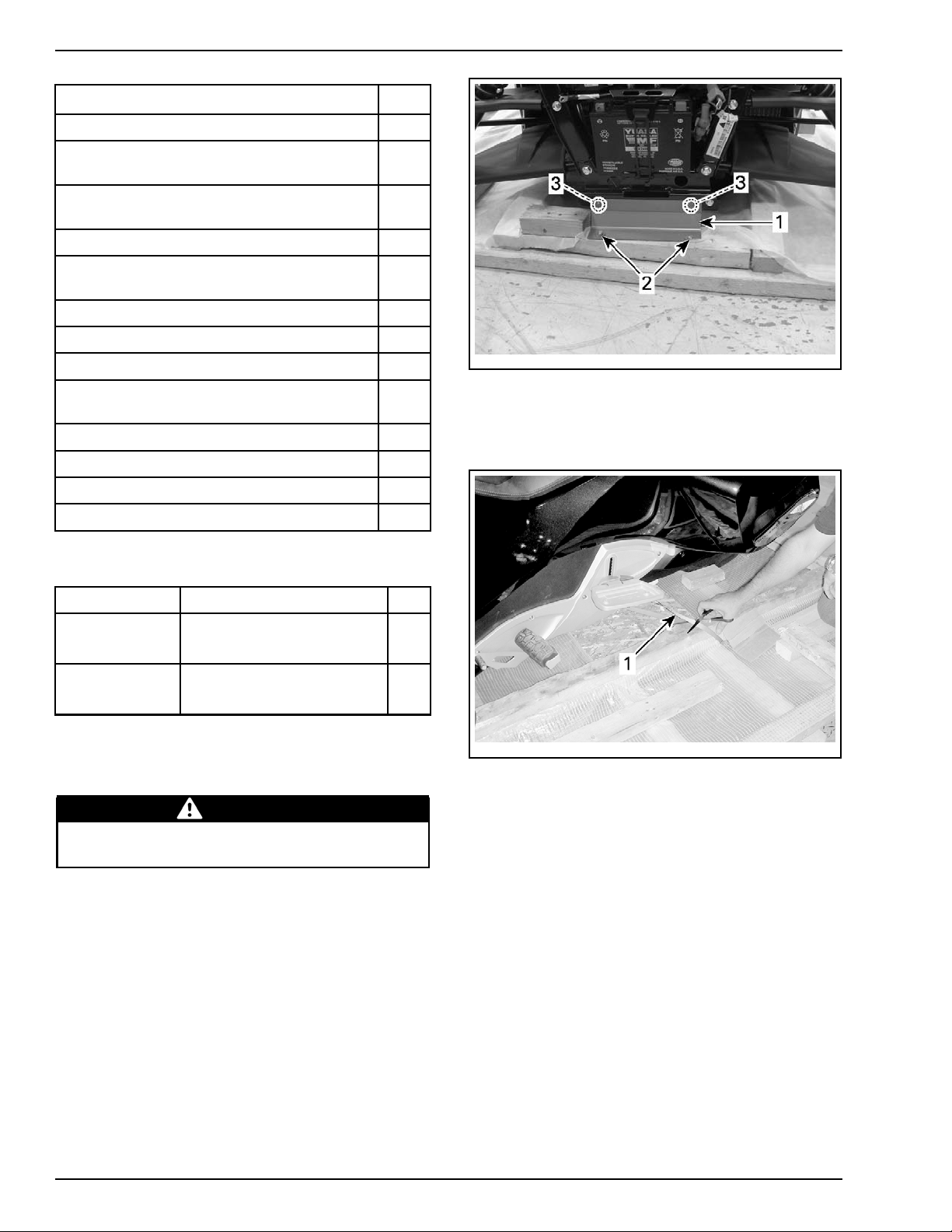
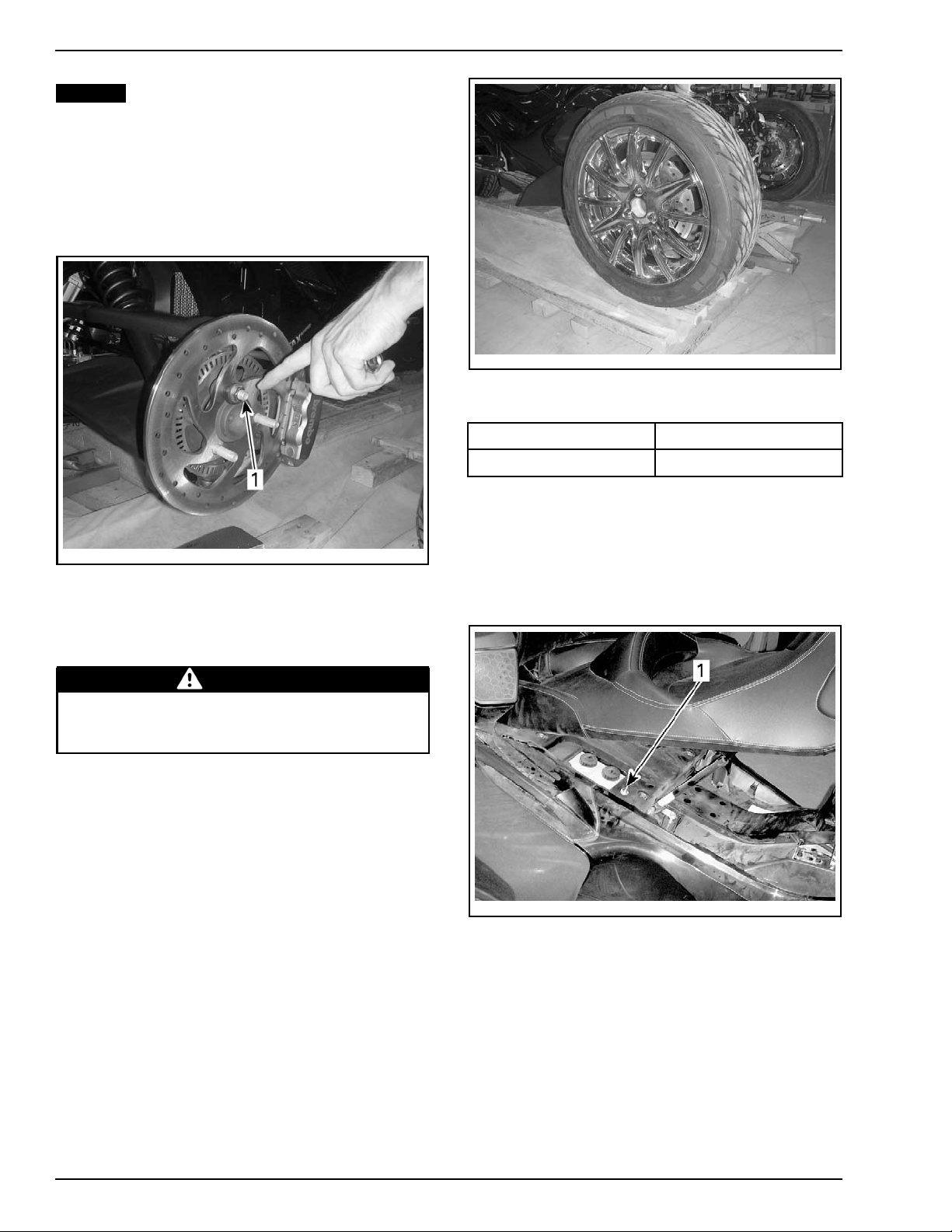
Lifting the Front of Vehicle ................... 6
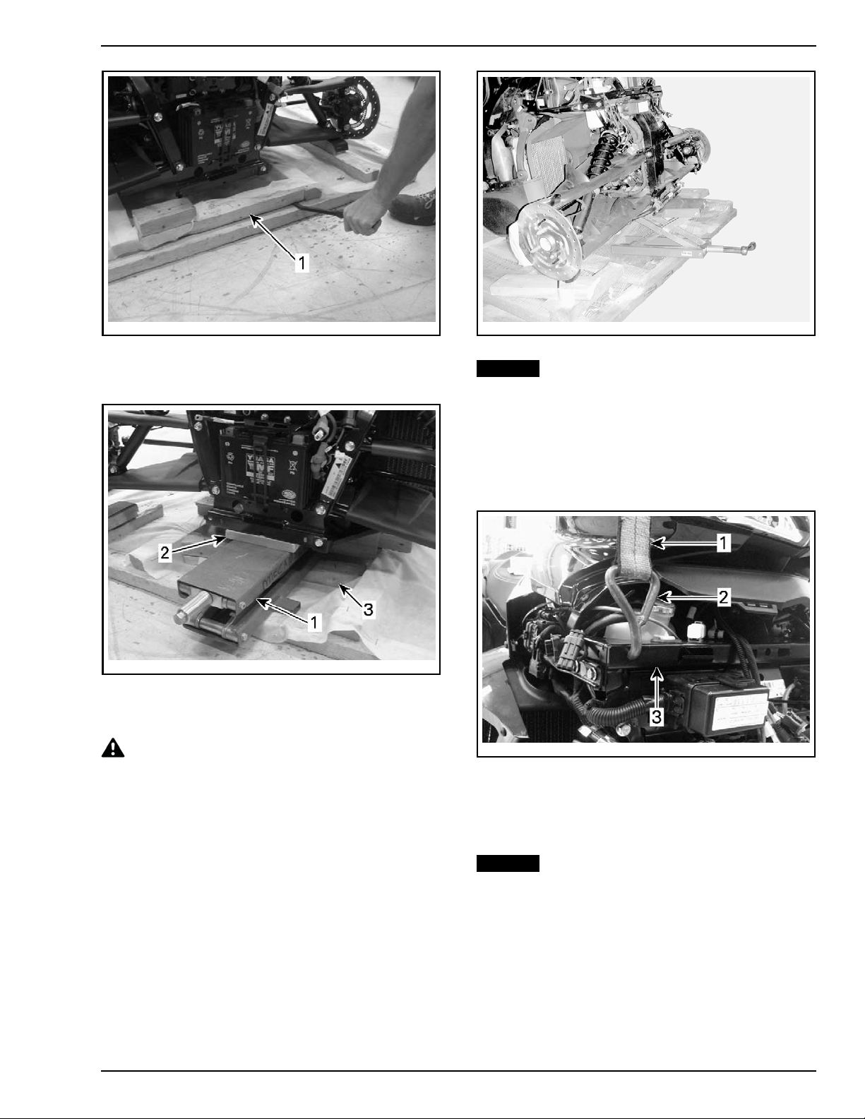
Front Wheels Installation ...................... 7
Vehicle Removal ................................ 8
PARTS TO BE INSTALLED................. 11
Front Cargo Module ....... .............. ....... 11
Battery ........................................... 15
Body Parts Installation ......................... 16
Front Fenders ................................... 19
Windshield....................................... 20
Antenna.......................................... 21
Hang Tag and Safety Labels .................. 21
Licence Plate.................................... 22
Accessories Installation........................ 22
Vehicle Decals................................... 22
Key Barrel - Trailer RT 622..................... 22
FLUIDS......................................... 22
General Guidelines ............................. 22
Fuel............................................... 22
Engine Oil........................................ 23
Clutch Fluid (SM5 Model) ..................... 24
Engine Coolant.................................. 25
Brake Fluid....................................... 26
SETUP ......................................... 27
Guidelines ....................................... 27
Tires Pressure................................... 27
Drive Belt ........................................ 28
Clutch Lever..................................... 29
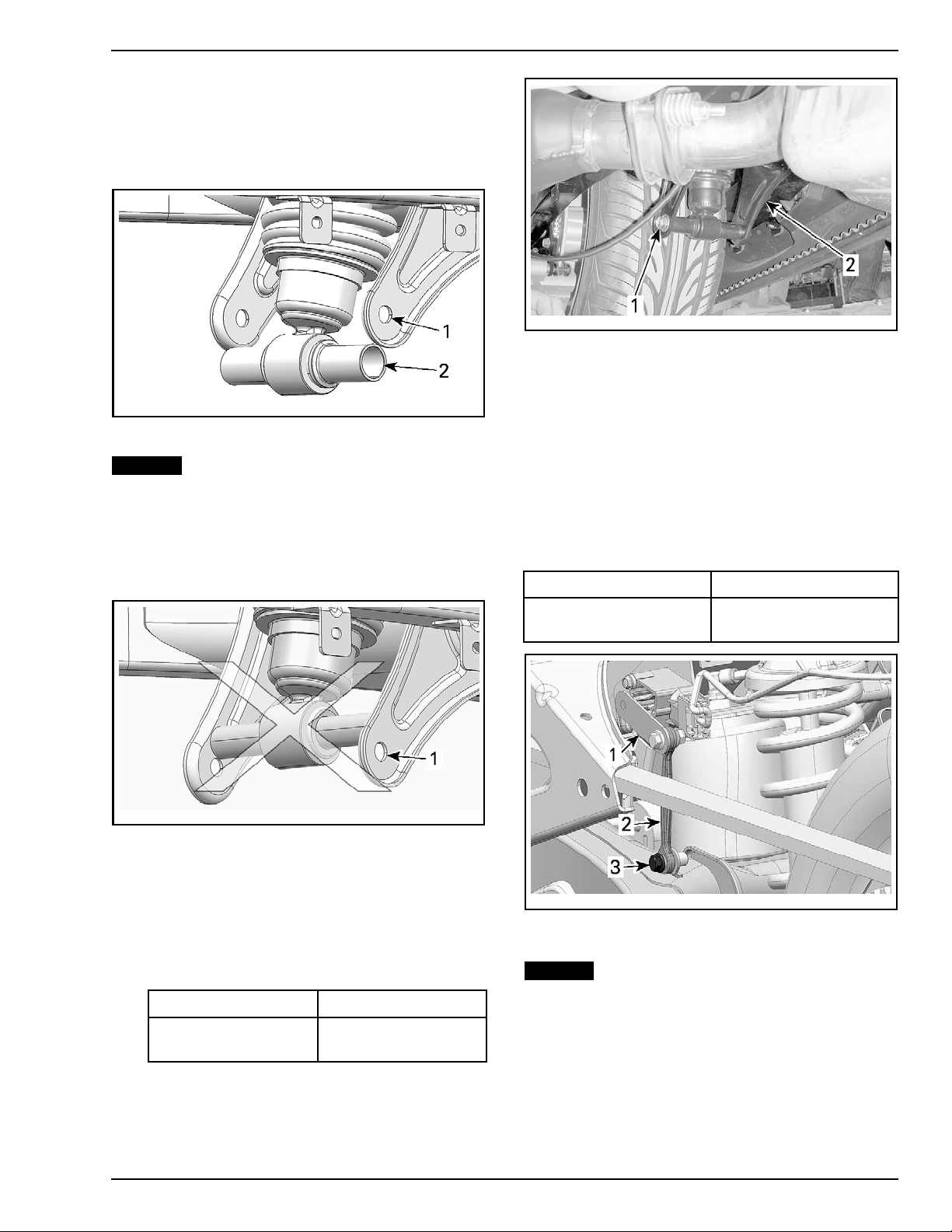
Suspension ...................................... 29
Lights............................................. 30
Storage Compartment Covers................ 32
Clock Setting.................................... 33
B.U.D.S. Programming......................... 34
ASSEMBLY INSPECTION.................. 36
FINAL INSPECTION ......................... 36
Vehicle Test Run................................ 36
Vehicle Cleaning ................................ 37
Delivery to Customer .......................... 38
SPECIFICATIONS ............................ 39
Canada and USA................................ 39
Europe ........................................... 43
Printed in Canada. (rbl2013-004_rev2 en CDI / SC)
©2012 Bombardier Recreational Products Inc. and BRP US Inc. All rights reserved. 1/47
®™ and the BRP logo are trademarks of Bombardier Recreational Products Inc. or its affiliates.

IMPORTANT NOTICE
This bulletin must be used in conjunction with the check list enclosed in the bag with the
OPERATOR’S
GUIDE
. Make sure that Spyder roadster
PRE DELIVERY CHECK LIST
is completed and signed.
WARNING
To obtain warranty coverage, predelivery procedures must be performed by an authorized BRP
Can-Am roadster dealer/distributor. Apply all necessary torques as indicated.
NOTE: The information and components/system descriptions contained in this document are correct at
the time of publication. BRP however, maintains a policy of continuous improvement of its products with-
out imposing upon itself any obligation to install them on products previously manufactured.
Due to late changes, there might be some differences between the manufactured product and the de-
scriptions and/or specifications in this document. BRP reserves the right at any time to discontinue or
change specifications, designs, features, models or equipment without incurring obligation.
The illustrations in this document show the typical construction of the different assemblies and may not
reproduce the full detail or exact shape of the parts. However, they represent parts that have the same
or similar function.
The content of this bulletin is designed as a guideline only. All mechanics performing predelivery
procedures should have attended the current model-year service training.
Further information or inquiries should be directed to your service representative and specific
SHOP MANUAL
sections.
Make sure the customer receives the
OPERATOR’S GUIDE
,
PREDELIVERY CHECK LIST
signed copy
and
SAFETY DVD
WARNING
Torque wrench tightening specifications must be strictly adhered to. Where specified, install new
locking devices (e.g. lock tabs, elastic stop nuts). If the efficiency of a locking device is impaired,
it must be renewed.
2 / 47 2013-2 SERVICE

UPDATE SUMMARY
This summary highlights updates to the Predelivery Inspection for MY2013. It does not supersede pro-
cedures detailed further in this publication.
IMPORTANT: Technicians should read and apply all procedures in this PDI bulletin as applicable to model.
APPLICABLE TO UPDATE DESCRIPTION REFERENCE
Front fenders crating method
PARTS AND SUB-CRATES
REMOVAL
RT Models
Battery installation
PARTSTOBEINST
ALLED
MODEL LISTING
YEAR MODEL MODEL NUMBER COUNTRY PREDELIVERY
KIT
SERIAL
NUMBER
A3DE Australia
A3DC, A3DD, A3DF,
A3DG Canada - USA
Spyder RT SM5
A3DB Europe
B2DC, B2DE, B2DF,
B2DG Canada - USA
Spyder RT SE5
B2DB, B2DD Europe
B9DK Australia
B9DM Brazil
B9DC, B9DE, B9DG,
B9DJ, B9DL, B9DN,
B9DP, B9DR
Canada - USA
Spyder RT Limited
SE5
B9DB, B9DD, B9DF, Europe
(P/N 703 100
390)
Spyder RT-S SM5
B5DB, B5DC,
B5DD,B5DG, B5DH,
B5DJ, B5DK, B5DL
Canada - USA
A4DB, A4DK Australia
A4DL Brazil
A4DC, A4DE, A4DG,
A4DM, A4DN, A4DP,
A4DR, A4DS
Canada - USA
2013
Spyder RT-S SE5
A4DD, A4DF, A4DT Europe
(P/N 703 100
391)
All
SERVICE 2013-2 3 / 47

UNCRATING
Crate Cover Removal
NOTICE Allowing the crate to drop may cause
serious damage to vehicle.
1. Position the crate on a firm, level surface.
2. Carefully cut both ends of crate tarpaulin to lo-
cate the front of vehicle.
rbl2010-002-001
CUT BOTH END OF CRATE TARPAULIN
3. Remove all screws holding crate cover to crate
base.
4. Tilt cover from the front side of the vehicle then
pull cover toward you to clear vehicle fascia.
NOTICE Do not raise cover vertically. Tilt
cover located on the front side of the vehicle.
Refer to illustration.
rbl2013-002-001_a
TYPICAL - TILT COVER THEN PULL IT
rbl2010-002-004_a
FRONT OF VEHICLE
1. Pull crate cover to clear front fascia of the vehicle
NOTICE The crate cover must be pulled to-
ward the outside while lifting it to avoid to
damage vehicle.
NOTE: Screws that are used are Robertson†#2
type (or equivalent) that require the use of an ap-
propriate screwdriver.
Parts and Sub-crates Removal
NOTICE Be careful not to scratch the cover
bumper and the front fascia.
NOTE: The sub-crates are located on each side of
the vehicle.
1. Remove protective foam from vehicle.
rbl2010-002-005
2. On LH side, remove all screws holding front
cargo module sub-crate.
† Robertson is a registered trademark of Robertson Inc.
4 / 47 2013-2 SERVICE

rbl2013-002-002_a
TYPICAL - LH SIDE
1. Sub-crate that contains front cargo module
3. Remove windshield and front wheels from
crate base.
rbl2013-003-001_a
TYPICAL
1. Windshield
2. Front wheels
4. On RH side, remove six bolts and two fenders
from sub-crate.
rbs2011-014-002_a
TYPICAL - RH SIDE - SUB-CRATE THAT CONTAINS FRONT
FENDER
1. Bolts
5. On RH side, remove all nails holding front
fender sub-crate and remove sub-crate.
Parts Check
Ensure that the crate includes the following items
(inside front storage compartment or secured to
front of vehicle):
NOTE: Empty all contents from front storage com-
partment.
DESCRIPTION MODEL QTY
Operator's
guide 1
Predelivery
check list1
Safety DVD 1
Predelivery kit 1
Service covers 2
Windshield trim 2
Wheel caps
All
2
Front cargo
liner
RT-S
RT Limited 1
The predelivery kit includes the following items:
DESCRIPTION (LOCATION) QTY
Wheel lug nut - black (front wheels) (RT-S) 6
Wheel lug nut - chrome (front wheels) (RT
andRTLTD) 6
Plastic bushing (rear suspension) 2
M10 x 140 hexagonal flange screw (rear
suspension) 1
M10 elastic flange nut (rear suspension) 1
M6 x 20 hexagonal flange screw (rear
suspension) 1
SERVICE 2013-2 5 / 47

DESCRIPTION (LOCATION) QTY
M6 caged nut (front cargo module) 1
Black M6 x 20 hexagonal flange screw (front
cargo module) 4
Gold M6 x 20 hexagonal flange screw (front
cargo module) 2
Plastic rivet (service cover) 2
Battery installation kit (2 bolts and 2 nuts)
(battery) 1
M6x20Torxs
crew (front panels) 2
Plastic washer (front panels) 2
M14 jam nut (headlights) 2
M8 x 20 hexagonal flange screw (front
fenders) 8
M6 x 20 Torx screw (windshield) 4
M5 x 25 countersunk Torx screw (windshield) 2
M5 retaining nut (windshield) 2
Windshield spacer (windshield) 2
Ensure that the following items are included in-
side the rear cargo compartment:
DESCRIPTION MODEL QTY
iPOD†cable –RT-S
– RT Limited 1
Audio auxiliary
cable
–RT-S
– RT Limited 1
Remove the antenna from the sub-crate.
Lifting the Front of Vehicle
WARNING
No one should be standing in front or at the
back of the vehicle while straps are being cut.
1. Remove plate retaining front of vehicle to crate
base by removing screws and nuts.
rbl2013-003-002_a
1. Plate
2. Screws
3. Screws and nuts
2. Remove strap retaining side of vehicle to crate
base.
rbl2010-002-011_a
TYPICAL
1. Side strap
NOTE: The following steps will describe two
methods to lift the front of the vehicle. The
conventional one uses a hydraulic jack and the
alternate one uses a chain block. Use the proper
method according to your shop layout.
Conventional Method
1. Remove piece of wood located at the front of
the vehicle.
NOTE: This piece of wood can be used to level the
jack at next step.
†iPod is a trademark of Apple Inc.
6 / 47 2013-2 SERVICE

rbl2013-003-003_a
1. Wood piece to remove
2. Install a jack with a piece of wood on top to
increase contact surface.
rbl2013-003-004_a
TYPICAL - FRONT OF VEHICLE
1. Jack
2. Wood piece
3. Wood piece removed earlier
CAUTION Approach with care when vehi-
cle is jacked because it may be unstable.
3. Lift the vehicle.
rbl2010-002-016
TYPICAL
NOTICE Never lift vehicle by the suspension
arm.
Alternate Method
1. Install proper straps with hooks on RH and LH
lateral supports of vehicle.
NOTE: Insert hooks through the holes in the
frame.
rbl2013-003-005_a
1. Strap
2. Hook
3. Frame
2. Hook straps on an appropriate lifting kit.
3. Lift vehicle using a chain block.
NOTICE Never lift vehicle by the suspension
arm.
Front Wheels Installation
1. Clean front and rear brake discs using XPS
BRAKES AND PARTS CLEANER (USA) (P/N 219
701 705) and a clean rag.
SERVICE 2013-2 7 / 47

NOTICE A thin layer of anticorrosion treat-
ment is present on the brake discs and must
be removed before using the vehicle. Not con-
forming to this procedure may lead to a brake
chattering squeaking and brake pad replace-
ment would be necessary.
2. Remove nut securing front brake discs to vehi-
cle.
rbl2013-003-006_a
1. Nut
3. Install front wheels on vehicle.
4. Ensure that the rotation direction shown by the
arrow is respected.
WARNING
The tires are only designed to rotate in one di-
rection. Do not switch the left and right front
wheels.
5. Tighten wheels lug nuts by hand (from PDI kit).
6. Lower vehicle on crate base.
7. Remove the jack.
rbl2013-003-007
TYPICAL
8. Torque wheels lug nuts.
PART TORQUE
Wheel lug nut 105 N•m (77 lbf•ft)
9. Install wheel caps (inside front storage com-
partment).
Vehicle Removal
1. Locate ACS suspension pneumatic valve then
unscrew cap.
rmo2010-001-056_a
1. Pneumatic valve
2. From underneath of vehicle, locate the bottom
of the rear shock absorber.
3. Get the following hardware from the PDI kit:
– M10 x 140 hexagonal flange screw
– M10 elastic flange nut
–Pla
stic bushings.
4. Install the 2 plastic bushings over the steel
sleeve at the bottom of the shock absorber.
8 / 47 2013-2 SERVICE

5. With the help of another person, slightly inflate
the ACS spring while your assistant, from the
LH side of the vehicle, monitors the alignment
of the bottom of the shock absorber (anchoring
holes) with the bottom of the lower brackets.
rbs2010-012-010_a
1. Lower bracket hole
2. Anchoring holes
NOTICE Adding air may create rapid high
changes because of the small air volume
in the ACS spring. The anchoring hole of
shock absorber must NEVER exceed the lower
bracket holes when adding air into ACS spring.
To avoid damaging the ACS system, DO NOT
exceed 551 kPa (80 PSI) into the ACS spring.
rbs2010-012-004_a
1. Lower bracket hole
6. Secure shock absorber as follows:
6.1 Using the passenger grab handles, slightly
lift the rear of the vehicle by HAND to align
both bushings on lower bracket hole.
6.2 Install M10 x 140 hexagonal flange screw.
6.3 Install and torque M10 elastic flange nut.
PART TORQUE
M10 elastic
flange nut 48 N•m (35 lbf•ft)
rbl2010-002-022_a
1. Shock absorber bolt
2. Lower bracket
RT-S and RT Limited Models
7. Install the link of the ACS position sensor to
swing arm.
7.1 Position the ACS position sensor lever
rearward.
7.2 Place the link on the outside of swing arm
bracket.
7.3 Secure the link using M6 x 20 hexagonal
flange screw (from PDI kit)
PART TORQUE
M6 x 20 hexagonal
flange screw 4N•m (35lbf•in)
rbl2011-001-001_a
1. ACS position sensor lever
2. ACS position sensor link
3. M6 x 20 hexagonal flange screw
NOTICE Ensure that ACS position sensor
lever orientation is correct.
SERVICE 2013-2 9 / 47

rbs2010-012-001
CORRECT ORIENTATION
rbs2010-012-002_a
INCORRECT ORIENTATION
8. Put a piece of wood behind the front wheels to
prevent the vehicle from rolling.
rbl2013-003-008_a
TYPICAL - FRONT RH WHEEL
1. Wood piece
9. Remove the piece of wood at the back of the
crate and insert it under the rear wheel.
rbl2013-003-009_a
TYPICAL
1. Wood piece
rbl2013-003-010_a
TYPICAL
1. Wood piece removed earlier
10. Remove the piece of wood from behind the
rear wheel.
rbl2013-003-011_a
TYPICAL
1. Wood piece behind rear wheel
11. Carefully remove pieces of wood positioned
earlier behind the front wheels.
12. With the help of your assistant, move vehicle
rearward out of the crate base.
10 / 47 2013-2 SERVICE

rbl2010-002-021_a
TYPICAL
NOTICE Always move vehicle rearward out of
the crate base.
PARTS TO BE INSTALLED
Front Cargo Module
WARNING
Make sure battery is not connected before
installing front cargo module. Do not install
front cargo module if battery is connected
because sparks can occur if tools touch bat-
tery terminals.
1. Assisted by another person, remove and dis-
card bolts holding the bottom and the top sec-
tions of sub-crate.
rbl2013-004-001_a
1. Tie-raps
2. Antenna
3. Lower retaining bolt
4. Upper retaining bolts
NOTE:Be careful not to lose the caged nut located
in the bottom fixation hole of the front cargo mod-
ule.
2. Open front storage compartment cover.
3. Ensure that the following cables and connec-
tors are accessible prior to installing front cargo
module, cut locking ties if required.
rbl2013-003-015_c
REFER TO THE FOLLOWING TABLE FOR ITEMS DESCRIPTION
ITEMS DESCRIPTION
1AAPTS sensor connector (hidden
on the illustration)
2Horn connector (hidden on
the illustration)
3
RH and LH auxiliary light connector
- Low beam light (CE)
- Fog light (option package)
4DLC connector (B.U.D.S.)
5Storage cover actuator connector
(option package)
6Storage cover switch connector
(option package)
7Storage cover cable
8 12 V power outlet (option package)
9Storage compartment light
(option package)
All Models
4. Before installing storage compartment, remove
the fuse service covers as follows:
4.1 Unzip the liner if applicable.
SERVICE 2013-2 11 / 47

rmo2013-005-002_a
1. Liner
4.2 Push down on the fuse service covers to
open the fuse boxes and pull the covers
off.
rmo2013-003-011_a
1. Left fuse service cover
2. Right fuse service cover
5. Remove mirrors as follows:
5.1 Hit with a sharp blow lower part of mirror
toward the rear to unlock it.
5.2 Slide mirror upwards to unhook it from up-
per slot.
rmr2011-087-009_a
Step 1: Hit with a sharp blow
Step 2: Slide mirror upwards
6. Remove middle side panel as follows:
6.1 Pull the rear of panel out of its grommet.
6.2 Slide down the top of the panel to free
panel hook.
6.3 Pull the bottom of the panel out of its
grommet.
6.4 Pull the front of the panel out of its grom-
met.
6.5 Slide the front of the panel to remove it.
rmo2010-008-003_a
REMOVAL SEQUENCE
7. Remove retaining screws from lower wind de-
flectors.
rbl2010-002-319_a
TYPICAL
1. Retaining screws of wind deflector
8. Remove upper retaining screws from top side
panels.
12 / 47 2013-2 SERVICE

rbl2010-002-320_a
TYPICAL
1. Upper retaining screws
9. Remove rear retaining screw from top side pan-
els.
rmr2010-038-006_a
TYPICAL
1. Rear retaining screw
10. Remove front retaining screw from top side
panels.
rbl2010-002-321_a
TYPICAL
1. Front retaining screw
11. Pull out lower part of top side panel to remove
it from grommets.
NOTE: Do not remove lower screws from top side
panel.
rbl2010-002-305
12. Remove top side panels by lifting them up-
wards.
rmr2010-038-009_a
TYPICAL
1. Top side panel
13. Remove upper retaining screws from front
fascia.
rmr2010-038-022_a
TYPICAL
1. Upper retaining screw
14. Remove middle retaining screws from front
fascia.
SERVICE 2013-2 13 / 47

rmr2010-038-023_a
TYPICAL
1. Middle retaining screw
15. Remove lower retaining screws and washers
from front fascia.
rmr2010-038-024_a
TYPICAL
1. Lower retaining screw
16. Remove front fascia from vehicle.
17. Use the following hardware to install front
cargo module on vehicle.
rbl2010-002-100_a
TYPICAL (RS SHOWN)
1. Black M6 x 20 hexagonal flange screws from PDI kit
2. Gold M6 x 20 hexagonal flange screws from PDI kit
3. M6 caged nut from PDI kit
NOTE: The second caged nut is already installed
on front cargo module.
18. Assisted by another person, position front
cargo module into support slots of vehicle.
19. Connect the following front cargo module con-
nectors and cable:
– AAPTS sensor connector
– Horn connector
– RH and LH auxiliary light connector (CE and
Option Package)
– DLC connector (B.U.D.S.) stowed in its re-
ceptacle
– Storage cover actuator connector (option
package)
– Storage cover switch connector (option
package)
– Storage cover cable
– 12 V power outlet
– Storage compartment light (option pack-
age).
CE Models
20. Install auxiliary light adjustment cable as fol-
lows:
20.1 Install adjustment cable through hole in
panel.
20.2 Tighten nut securing adjustment cable
(from PDI kit).
rmo2010-001-009_d
LEFT SIDE SHOWN
1. Install through this hole
All Models
21. Install M6 caged nut (from PDI kit) on a bottom
hole of storage compartment.
22. Install gold M6 hexagonal flange screws to se-
cure bottom of storage compartment. Do not
tighten yet.
14 / 47 2013-2 SERVICE

rmr2010-038-026_a
1. Gold M6 screws
23. Install black M6 hexagonal flange screws to
secure top of storage compartment.
rmr2010-038-025_a
1. Black M6 screws
24. Torque upper and lower M6 hexagonal flange
screws.
PART TORQUE
M6 hexagonal flange
screws 4.5 N•m (40 lbf•in)
Battery
The battery is located at the front of the cargo
module.
1. Pull down the rubber strap to disengage it from
the hook.
rbl2013-003-012_a
TYPICAL
1. Battery
2. Rubber strap
3. Hook
2. Remove bracket and battery from the vehicle.
rbl2013-003-012_b
TYPICAL
1. Battery
2. Bracket
NOTE: If you do not have a fully charged battery at
hand, the fully charged battery can be put in place
later.
IMPORTANT: It is of the upmost importance for
the battery life span that the battery initial charg-
ing be performed. Refer to the latest
CAN-AM
ROADSTER BATTERY ACTIVATION, CHARG-
ING AND MAINTENANCE
. Correct keywords to
search the latest Service Bulletin in BOSSWEB
or Knowledge Center are :"roadster battery
activation" including quotation marks.
3. Install charged battery in battery rack.
NOTICE Always charge battery before its in-
stallation on the vehicle.
SERVICE 2013-2 15 / 47

4. Connect RED (+) positive battery cables using
battery screws from the PDI kit.
WARNING
Always connect RED (+) cable first.
5. Tighten positive post battery screw.
PART TORQUE
Post battery screw 4 N•m (35 lbf•in)
rbl2013-003-013_a
1. Battery
2. RED (+) positive battery cable
3. Positive post battery screw
6. Apply DIELECTRIC GREASE (P/N 293 550 004) on
battery posts.
7. Connect BLACK (–) negative battery cables us-
ing battery screws from the PDI kit.
8. Tighten negative post battery screw.
PART TORQUE
Post battery screw 4N•m (
35 lbf•in)
9. Close RED rubber boot cover.
rbl2013-003-013_b
1. Battery
2. Black (-) negative battery cable
3. Negative post battery screw
4. RED rubber boot cover
10. Put bracket back in position on battery.
11. Install rubber strap and pull it down to engage
it with the hook.
rbl2013-003-014_a
1. Battery
2. Bracket
3. Rubber strap
4. Hook
Body Parts Installation
1. Install the following body panels:
– Front fascia
– Top side panels
–Midd
le side panels
– Mirrors.
Front Fascia
1. Install M6 x 20 Torx screws and plastic washers
(from PDI kit) to secure side panels.
16 / 47 2013-2 SERVICE

rmo2010-001-009_e
LEFT SIDE SHOWN
1. M6 x 20 Torx screw and plastic washer (from PDI kit)
2. Torque front fascia retaining screws and top
side panels retaining screws.
PART TORQUE
M6x20Torxscrew 3.5N•m(31lbf•in)
3. Install service covers as follows:
3.1 Open front storage compartment cover.
3.2 Insert upper tabs of service cover into the
vehicle grooves.
3.3 Push lower portion of service cover then
install plastic rivet (from PDI kit).
NOTICE For the RH service cover, pay at-
tention not to damage the FCS switch (if
equipped).
rmr2010-038-021_a
1. RH service cover
2. Plastic rivet
Panels and Mirrors
1. Install top side panel by lowering it.
rmr2010-038-009_a
1. Top side panel
2. Install lower retaining screws of top panel.
3. Install front retaining screw from top side panel.
rmr2010-038-008_a
1. Front retaining screw
4. Install left service cover using plastic rivet.
rmr2010-038-007_b
1. Left service cover
2. Plastic rivet
5. Install rear retaining screw on top side panel.
SERVICE 2013-2 17 / 47

rmr2010-038-006_a
1. Rear retaining screw
6. Install upper retaining screws on top side panel.
rmr2010-038-005_a
1. Upper retaining screws
7. Install mirror:
7.1 Carefully position the mirror using the top
stud.
7.2 Firmly push the mirror inwards until it en-
gages with the two bottom studs.
8. Install retaining screws on lower wind deflector
and install the top side panel.
rmr2010-038-004_a
1. Retaining screws of wind deflector
rmo2010-008-003_e
INSTALLATION SEQUENCE
9. Install the grille on the panel.
10. Push the front of panel in its grommet.
11. Rotate the panel and clip it on the support.
12. Push the bottom of the panel in its grommet.
13. Push the rear of the panel in its grommet.
14. Push the top of the panel to fix the plastic
hook.
All Models
15. After installing storage compartment, reinstall
the fuse service covers as follows:
15.1 Position the fuse service covers and push
down carefully until the fuse service cov-
ers engage.
rmo2013-003-011_a
1. Left fuse service cover
2. Right fuse service cover
15.2 Zip the liner if applicable.
18 / 47 2013-2 SERVICE

rmo2013-005-002_a
1. Liner
Front Fenders
1. Cut locking tie that hold harness bracket on
fender.
rbl2011-002-010_a
TYPICAL
1. Locking tie
NOTE: Do not remove protection from suspension
arms.
rbl2013-004-002_a
TYPICAL
2. Position front fender on vehicle.
rbl2011-002-011
TYPICAL
3. Route front ABS sensor harness and fender
light harness on fender hooks.
rbl2013-002-008_a
TYPICAL
1. ABS sensor harness
2. Fender light harness
3. Fender hooks
NOTE: Do not torque screws.
NOTE: Properly insert cable grommet on harness
bracket.
4. Connect fender light connector.
NOTE: Make sure harnesses are properly secured
through grommet.
SERVICE 2013-2 19 / 47

rbl2013-002-006_a
1. Fender light connector
rbl2013-002-009_a
1. Cable grommet
2. Harness bracket
5. Secure fender support on wheel hub.
6. Remove protection from suspension arms.
rbl2013-002-008_b
1. M8 x 20 hexagonal flange screws
7. Install 4 M8x 20 hexagonal flange screws to
complete the fender support installation.
FENDER SUPPORT RETAINING SCREW
24 N•m (18 lbf•ft)
8. Carry out the same procedure for the other
side.
Windshield
1. Install spacer on windshield support as illus-
trated.
rbl2012-002-001_a
1. Windshield spacer
2. Align windshield on windshield support.
3. Install M6 x 20 Torx screws (from PDI kit) to
secure windshield.
rmr2010-038-045_a
1. Windshield M6 x 20 screws
4. Torque windshield retaining screws.
PART TORQUE
Windshield retaining
screw 4.5 N•m (40 lbf•in)
5. Install windshield trim panels as follows:
5.1 Insert M5 retaining nut (from PDI kit) on
trim panel.
20 / 47 2013-2 SERVICE
Table of contents
Other BRP Motorcycle manuals