Technical data
and start-up
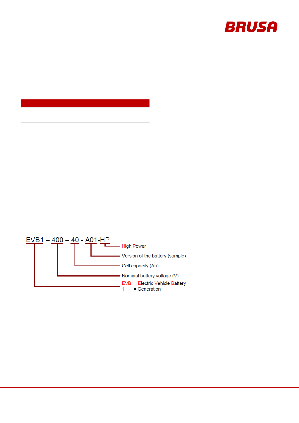
EVB1-350/400-40-HP
6.3 Warning Instructions on the Battery..........................................................................................29
6.4 Basic Principle for Vehicle Installation......................................................................................30
6.5 Safety measures for vehicle installation....................................................................................31
6.5.1 Principle of operation Interlock ..........................................................................................31
6.6 Basic Function Batterie EVB1-400/350-40-HP .........................................................................32
6.6.1 EVB1-400/350-40-HP Block Circuit Diagram.....................................................................33
6.6.2 Pre-charging Voltage.........................................................................................................34
6.6.3 Temperature Measurement / Temperature Monitoring ......................................................35
6.6.4 Balancing..........................................................................................................................36
6.6.5 Auto-reset of the Ah Meter ................................................................................................37
6.7 Overview of the Main Structural Components...........................................................................38
6.8 Dimensions and Installation Information...................................................................................39
6.8.1 Fixing Points......................................................................................................................39
6.8.2 Dimensions .......................................................................................................................40
6.8.3 Installation Position ...........................................................................................................40
6.9 Regulation and Control System................................................................................................41
6.9.1 Control via Terminal 15 (without CAN Bus) .......................................................................41
6.9.2 Control via Terminal 15 with Driving via CAN....................................................................42
7Connections.......................................................................................................................43
7.1 Circuit Connections..................................................................................................................43
7.2 Ground (GND)..........................................................................................................................44
7.3 Pin Assignment of Control Plug (Device-side)..........................................................................45
7.3.1 Pin 1 GND.........................................................................................................................46
7.3.2 Pin 2 AUX .........................................................................................................................46
7.3.3 Pin 3 EN............................................................................................................................47
7.3.4 Pin 4 PWML / PWM-out ....................................................................................................47
7.3.5 Pin 5 PWMP / PWM-out....................................................................................................48
7.3.6 Pin 9 CAN1L, Pin 10 CAN1H ............................................................................................48
7.3.7 Pin 8 APG, Pin 14 CANG, Pin 15 RS232G........................................................................49
7.3.8 Pin 11 RS232T, Pin 12 RS232R........................................................................................49
7.3.9 Pin 13 PRO.......................................................................................................................50
7.3.10 Pin 16 RFK1, Pin 17 RFK2, Pin 18 RFKC.........................................................................51
7.3.11 Pin 19 INT1, Pin 20 INT2...................................................................................................52