11: RS232 SERIAL PORT (DB9)
Serial data port utilizing a DB9 female connector. For
connection to system control systems such as Crestron
and AMX.
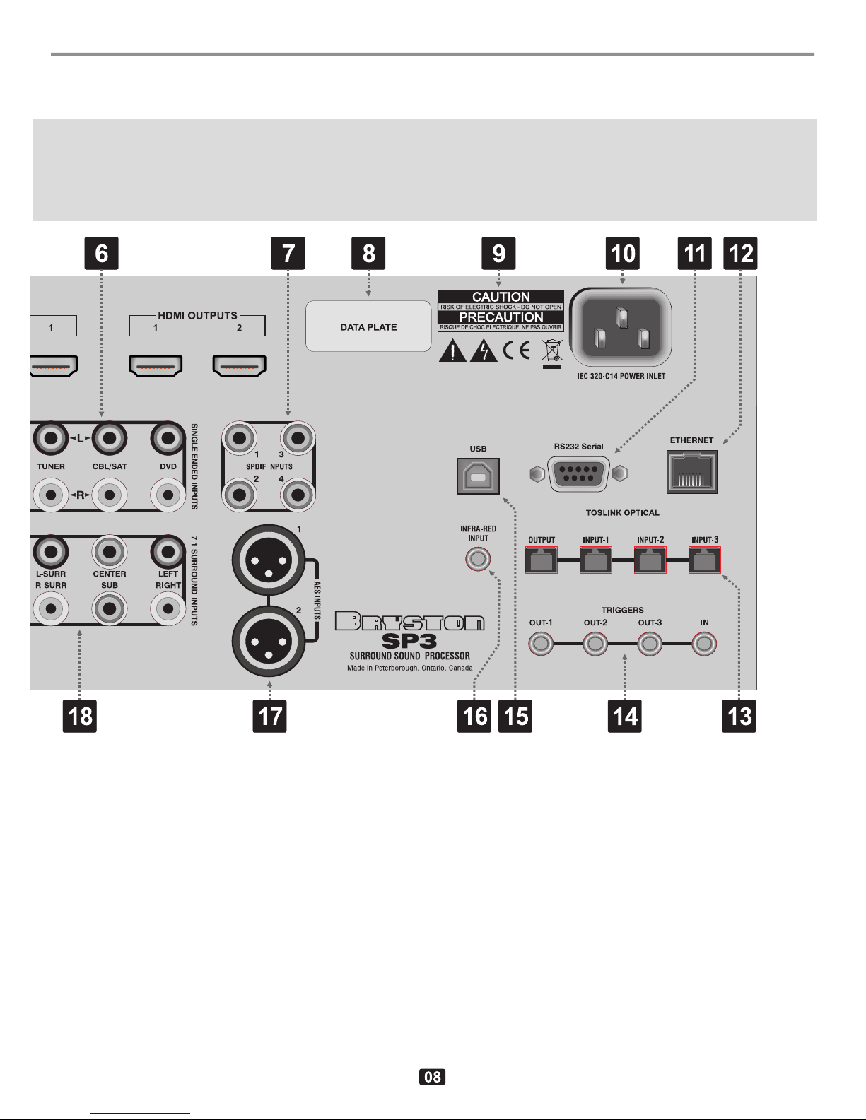
12: ETHERNET PORT (RJ45)
For interconnections to personal computers (and/or rout-
ers) to facilitate SP3 software updates and also for con-
trol functions through audio system controls (Crestron,
AMX, etc.) and computer control applications. This acts
an an HTTP server. See Appendix H for more info.
N.B. By default “Ethernet In Standby” mode is set OFF to enable
compliance with international standby power requirements.
13:
TOSLINK DIGITAL AUDIO OPTICAL INPUTS
The SP3 offers two assignable TOSLINK optical inputs.
These can be designated to any input using the OS
menu (“Other Settings”)on the LCD screen. Please note
that if you choose to assign an optical input to an input
with a coaxial input, the coaxial will be over-ridden and
the optical input signal will be used by the SP3.
The pro model replaces the two TOSLINK connectors
with a single AES/EBU Digital connector.
14: TRIGGER INPUTS & OUTPUT
Four 3mm two-conducter phone jacks with the tip being
positive and the sleeve being negative. A voltage of be-
tween 3 and 12V on the trigger input will turn the SP3 on.
Removing the trigger voltage will cause the SP3 to turn
off. The input voltage can be of either polarity, that is, the
phone plug tip can be positive and the sleeve negative,
or visa versa
The three outputs can be programmed to go either high
(+12Vdc, ±0.6V) or low (gnd) when specified inputs are
selected. These assignments are found in the SOURCE
menu (SOURCE TRIGGERS).
A delay can also be specified (in the SYSTEM MISC
TRIGDELAY menu) to delay the time when the trigger
output goes to the chosen state (high or low) after an
assigned input has been selected. See also Refer to the
Menu Tree on page 14
15: USB 2.0 TYPE A INPUT
Used as a digital audio input an as a control input for
certain audio control systems.
16: AUXILIARY INFRA-RED INPUT
A 3mm two conductor phone jack which will accept a
hardwired DC voltage that is the electrical equivalent of
the optical signal generated by an infrared emitter in a
remote control. This will primarily used as by infra-red
remote control extenders. The tip is positive, the sleeve
is negative and the signal level should be 5vdc max.
(Positive or “1”) and 0v or ground (negative or “0”)
17: AES/EBU BALANCED DIGITAL INPUT
Two 3 pin female XLR jacks for digital audio inputs con-
forming to the Audio Engineering Society/European
Broadcasting Union standard formalized as the IEC
60958 standard using 110 Ohm shielded twisted pair
wire.
18: SINGLE ENDED (UNBALANCED) 7.1 SUR-
ROUND SOUND INPUTS
Eight RCA jacks for connecting single-ended analog sur-
round signals to the SP3; Front-Left, Front-Right, Front-
Centre, Left Surround, Right-Surround, Back-Left, Back-
Right & Sub-woofer.
19: BALANCED ANALOG INPUTS
Four XLR female jacks (2 left/right pairs) referred to as
Balanced Input #1 and Balanced Input #2. These inputs
conform to the EIA RS-297 standard wherein pin #1 is
ground (chassis & shield), pin #2 is positive and pin #3 is
negative.
20: BALANCED ANALOG AUDIO 7.1 + 2 SUR-
ROUND SOUND OUTPUTS
Ten 3-pin XLR male connectors conforming to the EIA
RS-297 pinout (pin #1 = ground, pin #2 = positive and pin
#3 = negative). In addition to the usual eight 7.1 outputs
(Front-Left, Front-Centre, Front-Right, Surround-Left,
Surround-Right, Surround-Rear-Left, Surround-Rear-
Right and SubWoofer) there are two Auxiliary outputs (L-
Aux and R-Aux). The signals present on these outputs
can be programmed in the SYSTEM MISC AUX
menu. The two options are:
Stereo L+R : This puts a stereo down-mix signal on
the two AUX output jacks, the same ste-
reo down-mix that appears on the head-