Elmo SAXophone User manual

SAXophone
Installation Guide
April 2002
Elmo Motion Control
http://www.elmomc.com

Important Notice
This guide is delivered subject to the following conditions and restrictions:
This guide contains proprietary information belonging to Elmo Motion Control Ltd.
Such information is supplied solely for the purpose of assisting users of the
Saxophone servo amplifier.
The text and graphics included in this manual are for the purpose of illustration and
reference only. The specifications on which they are based are subject to change
without notice.
Information in this document is subject to change without notice. Corporate and
individual names and data used in examples herein are fictitious unless otherwise
noted.
Doc. no. SAXUGEN0402
Copyright 2002
Elmo Motion Control Ltd.
All rights reserved.
The Elmo Motion Control warranty for this product covers only the elimination of problems due to
manufacturing defects that result in impaired function. Specifically excluded from this warranty is the
elimination of problems caused by abuse, damage, neglect, overloading, wrongful operation and
unauthorized manipulations of the product. This product warranty is for a period of 12 months from the time
of operational startup but no longer than 18 months from shipment from the manufacturing plant. Damage
claims that exceed the warranty obligation – including consequential damages – will be rejected in all
cases. If any term or condition in this warranty is at variance or inconsistent with any provision or
condition (whether general or special) contained in or referred to in the Terms of Conditions of Sale
outlined at the back of Elmo’s Standard Acknowledgement form, then the latter shall prevail and be
effective.
Microsoft and Windows are registered trademarks of Microsoft Corporation. All other product and
company names mentioned in this manual maybe trademarks of their respective owners.
Elmo Motion Control Ltd.
64 Gisin St., P.O. Box 463
Petach Tikva
49103
Israel
Tel: +972 3 929-2300
Fax: +972 3 929-2322
Elmo Motional Control Inc.
900(H) River St., Kennedy
Industrial Park
Windsor, CT 06095
USA
Tel: +1 860 683-0095
Fax: +1 860 683-0036
Elmo Motion Control GmbH
Steinbeisstrasse 41
D-78056
Villingen-Schwenningen
Germany
+49 07720 8577-60
+49 07720 8577-70

Contents
Chapter 1: Safety Information............................................................................................... 1-1
1.1 Amplifier Compliance................................................................................................... 1-1
1.2 Safety Precautions.......................................................................................................... 1-1
1.3 Power Precautions ......................................................................................................... 1-2
Chapter 2: Introduction .......................................................................................................... 2-1
2.1 System Description ........................................................................................................ 2-1
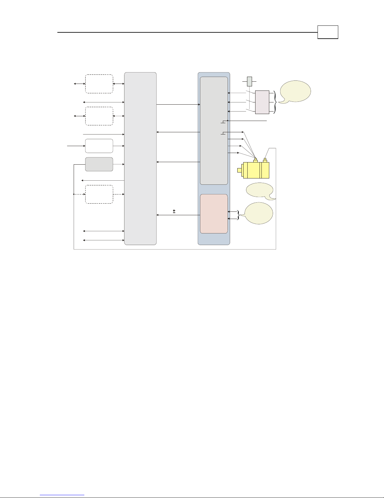
2.2 System Architecture....................................................................................................... 2-2
2.3 How to Use this Guide .................................................................................................. 2-3
Chapter 3: Installation ............................................................................................................ 3-1
3.1 Unpacking the System Components............................................................................ 3-1
3.2 Mounting the Saxophone.............................................................................................. 3-2
3.2.1 Mounting Directly onto Wall......................................................................... 3-2
3.2.2 Mounting on a DIN Rail................................................................................. 3-3
3.3 Connecting the Cables................................................................................................... 3-4
3.3.1 Wiring the Saxophone .................................................................................... 3-4
3.3.2 Connecting the Power Cables........................................................................ 3-5
3.3.3 Connecting the Motor Cables ........................................................................ 3-7
3.4 Powering Up................................................................................................................ 3-10
3.5 Initializing the System................................................................................................. 3-10
Chapter 4: Status Indications................................................................................................. 4-1
Appendix A: Pin Assignments ............................................................................................. A-1
A.1 Auxiliary Power Connector ......................................................................................... A-1
A.2 Committed I/O Connector .......................................................................................... A-1
A.3 General I/O Connector ................................................................................................ A-2
A.4 Feedback A – Encoder Option..................................................................................... A-3
A.5 Feedback A – Resolver Option .................................................................................... A-4
A.6 Analog I/O Connector ................................................................................................. A-5
A.7 Com1 .............................................................................................................................. A-6
A.8 Com2 .............................................................................................................................. A-7
A.9 Feedback B..................................................................................................................... A-7
Appendix B: Technical Specifications .................................................................................B-1
B.1 Power Ratings................................................................................................................B-1
B.1.1 1x230 VAC or 3x230 VAC Power Ratings ....................................................B-1
B.1.2 3x400 VAC Power Ratings .............................................................................B-1
B.1.3 Rated Specifications........................................................................................B-2
B.1.4 Auxiliary Power Supply.................................................................................B-2
B.1.5 Analog Input and Output ..............................................................................B-2
B.1.6 Feedback Supply Voltage..............................................................................B-3
B.2 Control Specifications....................................................................................................B-3
B.3 Feedback Options ..........................................................................................................B-4
B.4 Digital Input Interface ...................................................................................................B-5
B.5 Digital Output Interface ................................................................................................B-6
B.6 Fault Output ...................................................................................................................B-7
B.7 Single-Phase Operation .................................................................................................B-7
Elmo SAXophone Installation Guide
SAXUGEN0402

B.8 Mechanical Specifications .............................................................................................B-8
B.9 Recommended Wire Cross-sections.............................................................................B-8
B.10 Environmental Conditions............................................................................................B-8
B.11 Resolver ..........................................................................................................................B-9
B.12 Compliance Standards ..................................................................................................B-9
B.12.1 Quality Assurance ..........................................................................................B-9
B.12.2 Design ..............................................................................................................B-9
B.12.3 Safety................................................................................................................B-9
B.12.4 EMC................................................................................................................B-10
B.12.5 Workmanship................................................................................................B-10
B.12.6 PCB.................................................................................................................B-10
B.12.7 Packing...........................................................................................................B-10
B.13 Dimensional Drawings................................................................................................B-11
B.13.1 General Dimensions .....................................................................................B-11
B.13.2 Mounting Dimensions..................................................................................B-12
Appendix C: Supplemental Configuration Schematics ................................................... C-1
C.1 CANopen Configuration.............................................................................................. C-1
C.2 Auxiliary Encoder Configurations.............................................................................. C-2
Index...........................................................................................................................................I-1
Elmo SAXophone Installation Guide Contents
SAXUGEN0402
ii

Chapter 1: Safety Information
In order to achieve the optimum, safe operation of the Saxophone servo amplifier, it is
imperative that you implement the safety procedures included in this installation guide.
This information is provided to protect you and to keep your work area safe when
operating the Saxophone and its accompanying equipment. Read this chapter carefully
before you begin the installation process.
1.1 Amplifier Compliance
The end product used with the Saxophone must comply with the European Safety of
Machinery Directive 89/392/EEC safety requirements, and with the most recent versions
of the EN60204-1 and EN292-2 standards.
The Saxophone conforms to the following industry safety standards:
Item Safety Standard
Power conversion equipment Recognized UL508c
Insulation coordination, including clearance and
creepage distances of electrical equipment
In compliance with UL840
Safety of information technology equipment,
including electrical business equipment
In compliance with UL1950
Low Voltage Directive, 73/23/EEC In compliance with EN60204-1
1.2 Safety Precautions
Follow these safety guidelines when installing the Saxophone servo amplifier:
Power connection during operations: Disconnect the Saxophone servo amplifier
from its power source during all operations, such as installation, adjustment
maintenance and repair.
Qualified personnel: Ensure that only qualified personnel carry out any operation
relating to the Saxophone servo amplifier.
Live servo operations: Perform operations when the amplifier is disconnected from
the power source. Only qualified personnel who are fully aware of the dangers of
performing operations connected to the power source should carry out these
operations.
Components: Only certified Elmo representatives may replace damaged Saxophone
servo amplifier components.
Elmo Saxophone Installation Guide
SAXUGEN0402
1-1

Elmo SAXophone Installation Guide Safety Information
SAXUGEN0402
1-2
1.3 Power Precautions
Observe the following safety precautions when connecting the Saxophone servo
amplifier to a power supply or during power-up.
Power supply: The maximum AC/DC power supply connected to the instrument
must comply with the parameters outlined in this guide.
Grounding: The Saxophone servo amplifier contains grounding conduits for electric
current protection. Any disruption to these conduits may cause the instrument to
become hot (live) and dangerous.
Powering up: Before switching the Saxophone on, verify that all safety precautions
have been observed and that the installation procedures in this manual have been
followed.
The Saxophone SAX-xx/400 series is designed to operate only
from a 3-phase voltage source. The Saxophone SAX-xx/230
series is designed to operate from a 1- or 3-phase voltage
source. It can be connected directly to the line voltage. An
isolation transformer is not needed.

Elmo SAXophone Installation Guide
SAXUGEN0402
2-1
Chapter 2: Introduction
The Saxophone system includes the Saxophone servo amplifier and the Composer
software, which run in conjunction with your permanent-magnet synchronous motor.
The servo amplifier connects easily to your motor. You use the Composer software to set
the various servo and motor parameters that meet your specific configuration.
The Composer software is Windows-based and provides a plug-and-run tool that enables
users to quickly and simply set up the communication and the servo system. Refer to the
Composer Software Manual for more information.
This installation guide describes the Saxophone system and the steps for its setup,
installation and powering up. Following these guidelines ensures maximum functionality
of the Saxophone system.
2.1 System Description
The Saxophone system is designed for use with high-performance automated machinery.
The Saxophone series of servo amplifiers has been developed for permanent magnet
synchronous motors and incorporates digital velocity loop, a digital current loop and
sinusoidal commutation.
The Saxophone's basic configuration is a trimmerless velocity servo amplifier. All
adjustments to the velocity, current and commutation functions are made via the serial or
field bus (CANopen option) communication line, using a PC.
Independent control of the magnetic flux and the torque-generating current component
in motors is provided by sinusoidal control with phase advance algorithms. This is
particularly significant for permanent magnet synchronous motors and brushless motors
used in high-performance drives.
The Saxophone series' power source is a three-phase 400 VAC or one- or three-phase
230 VAC line. The control and auxiliary supplies are derived from a 24V AC or DC
supply that is isolated from the AC power bus. This allows a safe and economical "power
backup" feature that is essential for positioning systems.
The Saxophone series meets UL508C and the relevant CE regulations.

Elmo SAXophone Installation Guide Introduction
SAXUGEN0402
2-2
2.2 System Architecture
CANopen
(option)
Interface
Analog command
Aux. Encoder
Interface
Aux.
Encoder
RS232
Main Encoder
Interface
Resolver
Interface
(option)
Dadicated I/O:
Enable/Disable
Limit Switches
Abort
Fault
MCU
+
I/O
Motor
Feedback
RS485
Interface
(Option) AC1
AC2
AC3
M1
M3
M2
Main Power:
3x400 AC
3x230AC
Aux. Power:
24VDC
or
24VAC
Bridge Commands
(6 x PWM)
Status Lines
Current Feedback
Phase - M1
Phase - M3
Internal
Power
Supply
Power
Stage
Encoder output
+5v, 15v, 24v
PE
General I/O
Circuit
breaker
Contactor
PE
Figure 2-1: Saxophone Architecture Block Diagram
For three-phase supply voltage:
The circuit breaker current rating should be between 150% to 200% of the amplifier
current.
The circuit breaker voltage rating should be 460 VAC.
The contactor should be up to 150% of the amplifier current.
For single-phase supply voltage:
The circuit breaker current rating should be between 200% to 300% of the amplifier
current.
The circuit breaker voltage rating should be 460 VAC.
The contactor should be up to 200% of the amplifier current.

Elmo SAXophone Installation Guide Introduction
SAXUGEN0402
2-3
2.3 How to Use this Guide
In order to install and operate your Elmo Saxophone servo amplifier, you will use this
manual in conjunction with a set of Elmo documentation. Installation is your first step;
after carefully reading the safety instructions in the first chapter, the following chapters
provide you with installation instructions as follows:
Chapter 3, Installation, provides step-by-step instructions for unpacking, mounting,
connecting and powering up the Saxophone.
Chapter 4, Status Indications,lists the different symbols shown on the Saxophone display.
Appendix A, Pin Assignments,gives the pin-out information you need when preparing
the Saxophone cables.
Appendix B, Technical Specifications,lists all the amplifier ratings and specifications.
Appendix C, Supplemental Configuration Schematics,are additional diagramsto assist with
CANopen and encoder configurations.
Upon completing the instructions in this guide, your Saxophone servo amplifier should
be successful mounted and installed. From this stage, you need to consult higher-level
Elmo documentation in order to set up and fine-tune the system for optimal operation.
The following figure describes the accompanying documentation that you will require.
Programming
Setup
Installation Hardware installation guides
Composer software manual (doc. no. COMSFEN0202)
Command reference manual
Implementing Motion Control with Elmo Products
Figure 2-2: Elmo Documentation Hierarchy

Elmo SAXophone Installation Guide
SAXUGEN0402
3-1
Chapter 3: Installation
Before configuring and operating the Saxophone, you need to perform a number of
procedures to guarantee the best working conditions for the amplifier.
This chapter describes how to fully install the Saxophone: from unpacking it and
verifying its type designation, through wiring and mounting it, and then connecting it to
the required power.
There are five main steps in the Saxophone installation:
1. Unpacking and checking the system components
2. Mounting the Saxophone
3. Connecting the power cables and motor cables
4. Powering up
5. Performing initial setup and initialization
3.1 Unpacking the System Components
Before you begin working with the Saxophone system, verify that you have all of its
components, as follows:
The Saxophone servo amplifier
The Composer software and software manual
Optional mounting clips
The Saxophone is shipped in a cardboard box with Styrofoam protection.
To unpack the Saxophone:
1. Carefully remove the servo amplifier from the box and the Styrofoam.
2. Check the amplifier to ensure that there is no visible damage to the instrument.
3. To ensure that the Saxophone you have unpacked is the appropriate type for your
requirements, locate the part number sticker on the side of the Saxophone:

Elmo SAXophone Installation Guide Installation
SAXUGEN0402
3-2
The P/N number at the top gives the type designation as follows:
4. Verify that the Saxophone type is the one that you ordered, and ensure that the
voltage meets your specific requirements.
3.2 Mounting the Saxophone
The Saxophone has been designed for two standard mounting options:
Attaching directly to the wall with screws
Mounting on a DIN rail
With either type of mounting, be sure to leave about 10 cm (4 in) above and below the
instrument for heat dissipation.
3.2.1 Mounting Directly onto Wall
The vertical mounting strip at the back of the Saxophone enables you to screw the
amplifier directly into a wall.
To mount the Saxophone with the mounting strip:
1. On the back of the amplifier, push the mounting strip up until it clicks and locks.
The top lip (with the hole) should be exposed.
Figure 3-1: Extending the Mounting Strip Figure 3-2: Mounting Strip Fully Extended

Elmo SAXophone Installation Guide Installation
SAXUGEN0402
3-3
2. Mount the Saxophone vertically onto the wall with two screws, one through the top
hole of the mounting strip and one at the bottom.
3.2.2 Mounting on a DIN Rail
At the top rear of the Saxophone, a horizontal groove lets you quickly and easily snap the
Saxophone onto a DIN rail in your work area
To mount the Saxophone on a DIN rail:
1. Be sure that the vertical mounting strip (with the hole at the top) is pressed down
fully and does not protrude from the top of the instrument.
Figure 3-3: Mounting Strip Pressed Down
2. Tilt the Saxophone back towards the top part of the DIN rail.
Figure 3-4: Attaching Top Part of Mounting Groove to DIN Rail

Elmo SAXophone Installation Guide Installation
SAXUGEN0402
3-4
3. Press the Saxophone down to a vertical position until it clicks onto the DIN rail.
Figure 3-5: Saxophone Mounted on DIN Rail
3.3 Connecting the Cables
3.3.1 Wiring the Saxophone
Once the Saxophone is mounted, you are ready to wire the device. Proper wiring,
grounding and shielding are essential for ensuring peak servo operation and
performance.
Follow these instructions to ensure safe and proper wiring:
Keep the motor wires as far as possible from the signal level wiring (such as for
feedback and control).
If additional inductors (chokes) are required, keep the wires between them and the
amplifier as short as possible.
Minimize lead lengths as much as is practical. Although the amplifier is protected
against long (inductive) supply wires, the leads should be as short as possible. If the
cable length exceeds 10 m (35 ft), consult Elmo for further instructions.
Use twisted pairs and shielded wires whenever possible. Avoid running them in
close proximity to power leads or other sources of EMI noise.
Tie grounded components together at a single point (star connection). Then tie this
point with a single conductor to an earth ground point.
After completing the wiring, carefully inspect all wires to ensure tightness, good
solder joints and general safety.

Elmo SAXophone Installation Guide Installation
SAXUGEN0402
3-5
3.3.2 Connecting the Power Cables
Access the power terminal connections on the Saxophone servo amplifier by removing
the front safety cover located at the bottom of the front panel of the unit, as shown below:
Figure 3-6: Removable Bottom Saxophone Panel
After removing the safety cover, the power terminal connections are visible, as follows:
12
6 7 89
345
Connector No. Signal Function
1 24V AC/DC auxiliary power
2 24V AC/DC auxiliary power
3 M1 Motor phase U
4 M2 Motor phase V
5 M3 Motor phase W
6 PE Protective earth
7 AC1 Main voltage phase 1
8 AC2 Main voltage phase 2
9 AC3 Main voltage phase 3
Figure 3-7: Saxophone Power Cable Connectors

Elmo SAXophone Installation Guide Installation
SAXUGEN0402
3-6
Before connecting cables to the power terminal, it is important to organize your cables to
simplify the connection process. Refer to Appendix A, Pin Assignments, for more
information about the cables required for connection to the Saxophone.
The power connections are as follows:
Auxiliary power supply: Supplies power to the Saxophone logic board. The required
voltage is 24V AC/DC.
Motor supply: Supplies power for the motor output.
Motor
M1
M2
M3
A
B
C
Chassis
PE
SAXOPHONE
Figure 3-8: Saxophone – Motor Power Connections
Power supply: Supplies power to the Saxophone.
To connect the power cables:
1. On the open section at the bottom of the Saxophone front panel, connect the
auxiliary power supply to the J2-Aux Power points.
Note:
The DC cables (plus and minus) can be placed in either connector.
2. Connect the motor power cables to the J1-Power M1, M2 and M3 points. Ground the
motor to the PE point. Refer to the data sheet of your motor to determine which
cables are for the motor and which is for grounding.
3. Connect the 3-phase power supply to the J1-Power AC1, AC2 and AC3 points. Also,
be sure to ground the power supply to the PE point.

Elmo SAXophone Installation Guide Installation
SAXUGEN0402
3-7
Note:
You may connect the motor power cables in any order and the Composer
software will automatically configure the system. For more information
about configuration, refer to the Composer Software Manual.
4. Reattach the safety panel to cover the motor and power connectors.
3.3.3 Connecting the Motor Cables
The Saxophone servo amplifier has a front panel that provides easy-to-use connections
for all required cables. These connections are through 9-pin, 15-pin or 25-pin D-type
ports; they support several types of configurations and interfaces.
Figure 3-9: Saxophone Front Panel
The following cables must be connected:
Main feedback cable
Communication cable
I/O cables
Refer also to Appendix A, Pin Assignments.

Elmo SAXophone Installation Guide Installation
SAXUGEN0402
3-8
3.3.3.1 Main Feedback Cable
The main feedback cable is used to transfer feedback information from the motor to the
Saxophone. You should select this cable according to the feedback type of your motor:
either Encoder or Resolver. Consult your motor documentation for more information.
Refer to Appendix A for more information about this cable.
To connect the main feedback cable, insert the main feedback cable from the motor into the
Feedback A port on the Saxophone servo amplifier, using a 15-pin, D-type female
connector.
3.3.3.2 Communication Cable
The communication cable is used to transfer configuration information from the PC to the
Saxophone.
The communicationinterface may differ according to the user’s hardware. The
Saxophone can communicate using the following options (explained fully in Appendix
A):
RS-232: Connects to the Com1 port of the Saxophone. This is the most common
option.
RS-485: Connects to the Com1 port of the Saxophone.
CANopen: Connects to the Com2 port of the Saxophone (field bus). Also requires an
RS-232 cable.
Note:
Ensure that each servo drive is allocated a unique ID. Otherwise, the
CANopen network may hang.
In order to benefit from CANopen communication and the CiA DS-301 CANopen
standard, the user must have a good understanding of the basic programming and
timing issues of a CANopen network.
To connect the communication cable:
For an RS-232 connection, insert the communication cable from the serial port of the
PC (Com1 or Com2) into the Com1 port on the Saxophone servo amplifier, using a
9-pin, D-type female connector.
For CANopen communication, connect a communication cable from the CANopen
network to Com2 of the Saxophone servo amplifier.

Elmo SAXophone Installation Guide Installation
SAXUGEN0402
3-9
Figure 3-10: Saxophone with Connected Communication and Feedback Cables
3.3.3.3 I/O Cables
The following table lists the I/O cables that you should connect according to your
specific requirements:
Cable Description
General Uncommitted digital IO
Type Plus: 2 input/output
Type Plus Plus: 6 digital input/output
Analog 2 analog input
1 analog output
Committed 4 dedicated input
1 dedicated output

3.4 Powering Up
After the Saxophone has been mounted, check that the cables are intact. The Saxophone
servo amplifier is then ready to be powered up.
To power up the system, switch on the main and auxiliary power supplies. A d appears on
the front panel display. The Saxophone is powered up and functional. For more
information about the display, refer to Chapter 4, Status Indications.
3.5 Initializing the System
After the Saxophone has been connected and mounted, the system must be set up and
initialized. This is accomplished using the Composer, Elmo’s proprietary Windows-based
software application. Install the application and then perform setup and initialization
according to the directions in the Composer Software Manual.
Elmo SAXophone Installation Guide Installation
SAXUGEN0402
3-10

Elmo SAXophone Installation Guide
SAXUGEN0402
4-1
Chapter 4: Status Indications
The following table lists the symbols shown on the Saxophone display.
Symbol Status Action
Disable Bridge is disabled (all switches are off), no fault.
Enable All OK, amplifier is ready.
Under Voltage Bus voltage is too low.
Over Voltage Bus voltage is too high.
SVP Internal power supply problem.
Shunt The shunt is operating.
Short Phases are shorted to each other or to the ground.
Ishort = 3 ×Ipeak
Temperature Amplifier temperature is too high.
Feedback Feedback loss.
FLS Forward switch is active according to the defined
logic (IL[3]).
RLS Reverse switch is active according to the defined
logic (IL[4]).
FLS&RLS Both switches are active.
Over Speed Speed exceeded high or low limitation (HL[2],
LL[2]).
IC Continuous current limit is active.
Over Current Current exceeded peak current limitation.
Undeclared
Fault
Fault not declared on LED; may be detected with
MF command.
Table of contents
Other Elmo Amplifier manuals
Popular Amplifier manuals by other brands

Luxman
Luxman L-430 owner's manual

Trends Audio
Trends Audio Trends Audio TA-10 user guide

Onkyo
Onkyo A-7070 Service manual

Hogtunes
Hogtunes REV 200SG KIT-RM installation manual

Applied Research and Technology’s
Applied Research and Technology’s AV Direct Artcessories user manual

Ground Zero
Ground Zero Uranium GZUA 1.1000DX owner's manual