Soundchoice PROAudio T-60FP User manual

T-60FP/T-120FP Mixer Amplifier
Operation Manual
www.scpaudio.com
MIC1
0
1
2
3
456
7
8
9
10 0
1
2
3
456
7
8
9
10
MIC2
0
1
2
3
456
7
8
9
10 0
1
2
3
456
7
8
9
10 0
1
2
3
456
7
8
9
10
MIC3 MIC 4 AUX
+12-12
0
+12
-12
0
0
1
2
3
456
7
8
9
10
POWER
ON
OUTPUT LEVEL
TAPECDTUNERLINE
BASS TREBLE MASTER
SOUNDCHOICE
PROAUDIO
T-60FP
MIXER AMPLIFIER
SOUNDCHOICE
PROAUDIO

www.scpaudio.com
SOUNDCHOICE
PROAUDIO
WARNING | The following contains potential safety hazards that may occur from mishandling and could result in
death or serious injury.
Safety Precautions
Be sure to read the instructions in this section carefully before use.•
It is important to observe all the safety and warning messages outlined in this manual at all times.•
We recommend you keep this manual handy for future reference.•
Safety Symbol and Warning Messages
Safety symbols and warning messages described below are used in this manual to prevent injury and property damage which could result from
mishandling. Before operating your product, read this manual and understand the safety symbols and messages so you are thoroughly aware
of the potential safety hazards.
When Installing the Unit
Do not expose the unit to rain or any environment where it•
may be splashed by water or other liquids as doing so may
result in fire or electric shock.
Only use the unit with the voltage specified as using a•
higher voltage may result in fire or electric shock.
Do not cut, kink or otherwise damage nor modify the power•
supply cord. In addition to this, avoid using this cord in
close proximity to heaters and never place heavy objects
(including the unit itself) on the power cord as doing any of
these may result in fire or electric shock.
It is important to replace the unit’s speaker terminal cover•
after completing connection as high voltage is applied to the
speaker terminals and touching these terminals may result in
electric shock.
At all time the unit’s ground wire needs to be safely•
grounded to the earth terminal to avoid electric shock.
Avoid installing or mounting the unit in unstable locations at•
all times as doing this may result in the unit falling causing
personal injury and /or property damage.
When the Unit is in Use
Should any of the following be found during use,•
immediately switch off the power, disconnect the power
supply plug from the AC outlet and contact your nearest
dealer. Make no further attempts to operate the unit as this
may cause fire or electric shock.
If you detect smoke or a strange smell coming from the•
unit
If water or any metallic object gets into the unit•
If the unit falls, or the case breaks•
If the power supply cord is damaged•
If the unit is malfunctioning•
As high voltage components are inside the unit, opening•
or removing the unit case may cause fire or electric shock.
Refer all servicing to your nearest dealer or Sound Choice Pro
Audio.
Do not place cups, bowls or other containers of liquid or•
metallic objects on top of the unit. Accidental spills into the
unit may cause fire or electric shock.
Do not insert nor drop metallic objects or flammable•
materials in the ventilation slots of the unit’s cover as this
may also result in fire or electric shock.

Page 3 of 9
CAUTION | The following contains potential safety hazards that may occur from mishandling that could result
in moderate or minor personal injury and/or property damage.
When Installing the Unit
Never plug in or remove the power supply plug with wet•
hands as doing so may cause electric shock.
When unplugging the power supply cord, be sure to•
grasp the power supply plug; never pull on the cord itself.
Operating the unit with a damaged power supply cord may
cause a fire or electric shock.
When moving the unit, be sure to remove its power supply•
cord from the wall outlet. Moving the unit with the power
cord connected to the outlet may cause damage to the
power cord, resulting in fire or electric shock.
Do not block the ventilation slots in the unit’s cover as doing•
so may cause heat to build up inside the unit and result in
fire.
Avoid installing the unit in humid or dusty locations,•
locations that generate sooty smoke or steam, near heaters
or exposing it to direct sunlight as doing so may result in fire
or electric shock.
When the Unit is in Use
Do not place heavy objects on the unit as they may fall or•
cause the unit to fall or break which may result in personal
injury and/or property damage.
Before switching the unit’s power on, ensure that the•
volume control is set to the minimum position as loud noise
produced at high volume when power is switched on can
impair hearing.
Do not operate the unit for an extended period of time with•
the sound distorting. This is an indication of a malfunction
which in turn can cause heat to generate and result in a fire.
Contact your dealer for cleaning requirements. If dust is•
allowed to accumulate in the unit over a long period of time,
a fire or damage to the unit may result.
As dust accumulates on the power supply plug or in the wall•
AC outlet, clean periodically to ensure a fire does not occur.
Ensure the plug is inserted in the wall outlet securely.
Switch off the power and unplug the power supply plug from•
the AC outlet for safety purposes when cleaning or leaving
the unit unused for an extended period of time to avoid fire
or electric shock.

www.scpaudio.com
SOUNDCHOICE
PROAUDIO

Page 5 of 9
Table of Contents
Key Features and Benefits ������������������������������������������������������������������������������������6
Front Panel�������������������������������������������������������������������������������������������������������������������������� 7
Rear Panel��������������������������������������������������������������������������������������������������������������������������� 8
Speaker Connections���������������������������������������������������������������������������������������������������9
XLR Connections �������������������������������������������������������������������������������������������������������������9
Rear Panel Connections������������������������������������������������������������������������������������������10
Specifications ������������������������������������������������������������������������������������������������������������������10
Dimensional Diagrams������������������������������������������������������������������������������������������������11

www.scpaudio.com
SOUNDCHOICE
PROAUDIO
Key Features and Benefits
Sound Choice Pro Audio T series public address mixer amplifiers have power ratings of 60 and 120 watts RMS. These sleek, attractive, very
reliable units provide a compact solution for PA system amplification and distribution.
Rated power: 60W/120W.•
AC and DC operation.•
Special low cut filter built-in.•
Front panel level meter and power indicator.•
Phoenix speaker output connectors for easy installation.•
4 Aux RCA inputs, with inter-lock to avoid cross talk.•
Built-in 2 and 4 tone chime. Switchable options.•
Preamp OUT and IN to insert signal processing equipment.•
Individual front panel input and master volume controls.•
Current limiter, overload, short circuit and thermal protection.•
Selectable priority inputs to duck background music when paging.•
4 balanced XLR mic inputs, each with phantom power switch.•
Constant voltage 100V, 70V and 50V lines and low impedance 4 ohm speaker terminals.•
T-60FP / T-120FP Mixer Amplifier

Page 7 of 9
Front Panel
MIC volume control1.
AUX volume control2.
Bass response adjustment3.
Treble response adjustment4.
Master volume control5.
Power switch ON/OFF6.
Protection indicator7.
Signal output level indicator8.
Select tape channel input9.
Select CD channel input10.
Select tuner channel input11.
Select line channel input12.
MIC 1
0
1
2
3
456
7
8
9
10 0
1
2
3
456
7
8
9
10
MIC 2
0
1
2
3
456
7
8
9
10 0
1
2
3
456
7
8
9
10 0
1
2
3
456
7
8
9
10
MIC 3 MIC 4 AUX
+12-12
0
+12-12
0
0
1
2
3
456
7
8
9
10
POWER
ON
OUTPUT LEVEL
TAPECDTUNERLINE
BASS TREBLE MASTER
1264 5
37
89
101112
SOUNDCHOICE
PROAUDIO
T-60FP
MIXER AMPLIFIER
www.scpaudio.com
SOUNDCHOICE
PROAUDIO
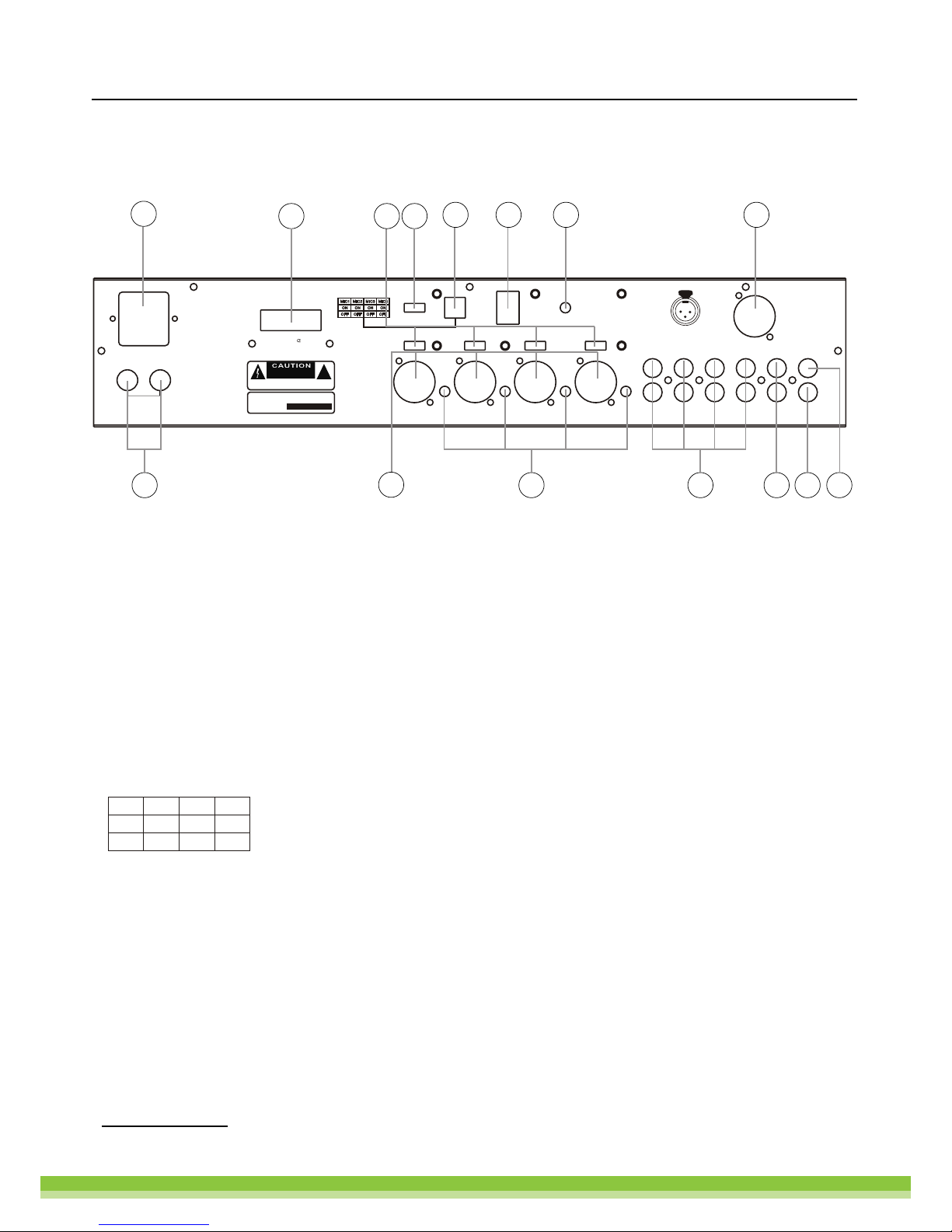
Rear Panel
24V DC backup battery supply13.
MIC (1~4) XLR microphone input14.
MIC (1~4) microphone gain control15.
Audio source RCA connectors16.
Recorder output RCA connectors17.
Power amplifier insert input18.
Pre amplifier output19.
Audio line level output20.
Selects mic priority
Chime volume control21.
Chime trigger22.
Dipswitch mic priority (1-4)23.
Switch to select 2 tone or 4 tone chime24.
MIC (1~4) phantom power select switch25.
Connectors for 4 ohms or 50V \ 70V and 100V speaker outputs26.
240V/50Hz IEC AC power connector27.
MIC1 MIC2MIC3MIC4
ON
OFF
ON
OFF
ON
OFF
ON
OFF
MICPRIORITY
~240V 50Hz
T1.5AL250V
RISK OF ELECTRIC SHOCK
DO NOTOPEN
RISQUE DE CHOC ELECTRICUS
-NE PAS QUVRIR
AVIS:
PUBLIC ADDRESS SYSTEM
SERIAL NO
:
MIC1 MIC2 MIC3 MIC4
ON
OFF
ON
OFF
ON
OFF
ON
OFF
TAPE CD TUNERLINE RECPREOUT
POWER IN
OUT
XLRBAL
1-GND
2-HOT+
3-COLD-
12
3
MICRO4
GAINGAINGAINGAIN
MICRO 3MICRO 2MICRO1
PHANTOMMIC PHANTOMMIC PHANTOMMIC PHANTOMMIC
VOLUME
CHIME
PRIORITY
MICPRIORITY
2T 4T
POWEROUT
100V
70V
50V
4
COM
BATT SUPPLY
+ 24V -
14 15 16 17 18 19
20
25
27
13
212223
2426
Page 9 of 9
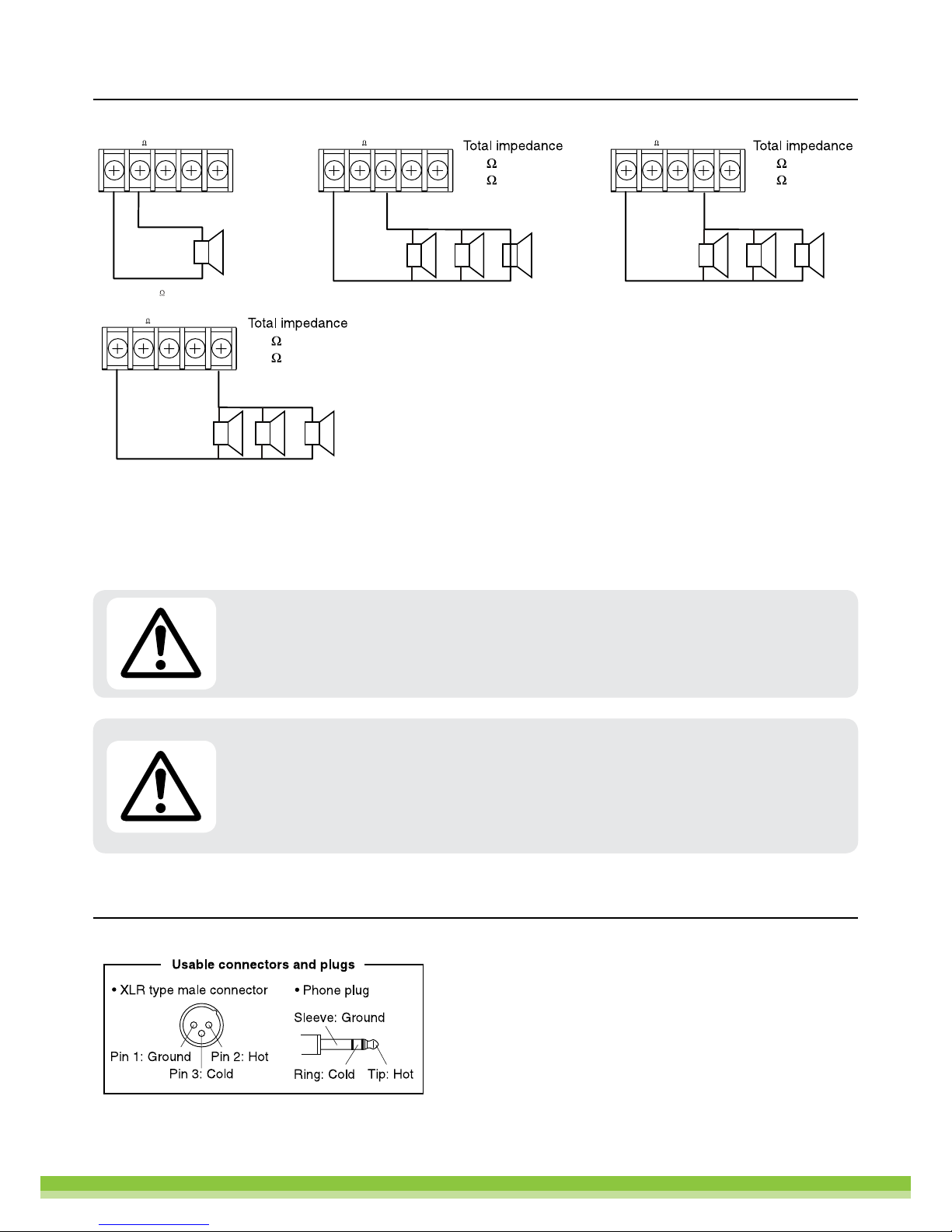
NOTE:
Do not use multiple speaker outputs at the same time. Only connect the speakers to one of the following outputs:
4 ohm, 50V, 70V or 100V terminal. Impedances indicated in the figures represent the total speaker system (load) impedances.
Speaker Connections
XLR Connections
70V LINE
50V LINE4
70V 100V
COM 4 50V70V 100V
COM 4 50V70V 100V
COM 4 50V
100V LINE
70V 100V
COM 4 50V
(T-60FP)
(T-120FP)
42
21
(T-60FP)
(T-120FP)
81
41
(T-60FP)
(T-120FP)
167
83
WARNING | Be sure to attach the supplied terminal cover after connecting the speaker cabling. High voltage
is applied to the speaker terminals, never touch these terminals to avoid electric shock.
OPERATION NOTE | Do not turn mixer amplifier on and off frequently. You should allow 10 seconds after
turning off the device, before turning it back on. Ensure the power supply matches the requirements listed
on the back of the device. Always operate this device with AC ground wire connected. If the device goes into
protection mode for any reason, it will auto-check and restart automatically if the issue has been resolved.

www.scpaudio.com
SOUNDCHOICE
PROAUDIO
Rear Panel Connections
Specifications
Model T-120FPT-60FP
Rated Power Output
4 Microphone Inputs
Sensitivity
S/N Ratio
Frequency Response
4 Auxiliary Inputs
Tuner and Tape Inputs
Sensitivity/Impedance
CD and Line Inputs
Sensitivity/Impedance
S/N Ratio
Frequency Response
Control
Bass
Treble
Chime
Outputs
Level/Impedance Output
Level/Impedance Recorder Output
Normal Distortion
Operating Condition
Mains Power Supply
Dimensions (D*W*H)
Weight
120W
12.5kg
60W
XLR
-50 /-2dB 2.5 / 500 mV
>68 dB
100 / 17.000 Hz (-3 dB)
RCA
200 mV /47 Koms
500 mV /47 Koms
90 dB
40/20.000Hz (-3 dB)
+12 dB
+12 dB
2 tone active for contact free in priority and BGM
775 mV /47Koms
200 mV /1Koms
< 0.1%
240V A C 50 Hz
484mm × 367mm × 88mm
10.5kg
SPEAKERS
LINK
INPUTS
AVIS:
:
XLRBAL
1-GND
2-HOT+
3-COLD
OUTPUTS
INPUTS
T5AL250V
POWER AMPLIFIER
ADDRESSTAG
COM
AUDIO
OUT
RR
LL
T1AL250V
~240V/50Hz
AVIS:
SERIAL NO
:
~240V50Hz
T1AL250V
AUDIO
OUT
R
L
CO
ADRESSTAG
AM
GND
ANTENNA
LOOPANTENNA
FM75
M
AVIS:
PUBLICA DDRESSSYSTEM
SERIALNO
:
CD PLAYER
AM / FM TUNER
MIC 1 MIC 2 MIC3 MIC4
DC 24V
~240V50Hz
T1.5AL250V
RISK OFELECTRIC SHOCK
DO NOT OPEN
RISQUE DE CHOC ELECTRICUS
-NE PAS QUVRIR
AVIS:
PUBLIC ADDRE SS SYSTEM
SERIALNO
:
MIC1 MIC2 MIC3MIC4
ON
OFF
ON
OFF
ON
OFF
ON
OFF
TAPECDTUNERLINEREC PRE OU T
POWER IN
OUT
XLR BAL
1-GND
2-HOT+
3-COLD-
12
3
MICRO 4
GAINGAINGAINGAI N
MICRO 3MICRO 2MICRO 1
PHANTO MMIC PHANTO M MIC PHANTOM MIC PHANTOMMIC
VOLUME
CHIME
PRIORITY
MIC PRIORITY
2T 4T
POWER OUT
100V
70V
50V
4
COM
BATTSUPPLY
+24V -
TAPE INPUT
RECORD OUT
INSERT AUDIO PROCESSOR EQUIPMENT
PLEASE USE BRIDGING CONNECTOR
WHEN INSERT IS NOT REQUIRED

Page 11 of 9
Dimensional Diagrams
CAUTION | As this mixer amplifier is convection cooled, it is important to keep a minimum of 100mm clear
space around the unit at all times to prevent airflow obstruction and subsequent overheating.
MIC 1
0
1
2
3
456
7
8
9
10 0
1
2
3
456
7
8
9
10
MIC 2
0
1
2
3
456
7
8
9
10 0
1
2
3
456
7
8
9
10 0
1
2
3
456
7
8
9
10
MIC 3 MIC 4 AUX
+12-12
0
+12-12
0
0
1
2
3
456
7
8
9
10
POWER
ON
OUTPUT LEVEL
TAPECDTUNERLINE
BASS TREBLE MASTER
SOUNDCHOICE
PROAUDIO
T-60FP
MIXER AMPLIFIER
~220V 50Hz
T1.5AL250V
RISK OF ELECTRIC SHOCK
DO NOTOPEN
RISQUE DE CHOCELECTRICUS
-NEPAS QUVRIR
AVIS:
PUBLICADDRESS SYSTEM
SERIAL NO
:
MIC1 MIC2 MIC3 MIC4
ON
OFF
ON
OFF
ON
OFF
ON
OFF
TAPE CD TUNER LINE RECPRE OUT
POWERIN
OUT
XLR BAL
1-GND
2-HOT+
3-COLD-
12
3
MICRO4
GAINGAINGAINGAIN
MICRO3MICRO2MICRO1
PHANTOMMIC PHANTOMMIC PHANTOMMIC PHANTOMMIC
VOLUME
CHIME
PRIORITY
MICPRIORITY
2T 4T
POWEROUT
100V
70V
50V
4
COM
BATTSUPPLY
+24V -
MIC 1
0
1
2
3
456
7
8
9
10 0
1
2
3
456
7
8
9
10
MIC 2
0
1
2
3
456
7
8
9
10 0
1
2
3
456
7
8
9
10 0
1
2
3
456
7
8
9
10
MIC 3MIC4 AUX
+12-12
0
+12-12
0
0
1
2
3
456
7
8
9
10
POWER
ON
OUTPUT LEVEL
TAPECDTUNERLINE
BASS TREBLE MASTER
SOUNDCHOICE
PROAUDIO
T-60FP
MIXER AMPLIFIER
484mm
6mm
>100mm >100mm
88mm
84mm
84mm
>100mm
94mm
436mm
340mm
325mm

12 Pearwood Lane
Robina Qld 4226
Australia
P� +61 413 676706
F� +61 7 5520 1991
www.scpaudio.com
SOUNDCHOICE
PROAUDIO
This manual suits for next models
1
Table of contents
Other Soundchoice PROAudio Amplifier manuals

Soundchoice PROAudio
Soundchoice PROAudio 120MA User manual

Soundchoice PROAudio
Soundchoice PROAudio 2120A User manual

Soundchoice PROAudio
Soundchoice PROAudio C4 Series User manual

Soundchoice PROAudio
Soundchoice PROAudio C2 Series User manual

Soundchoice PROAudio
Soundchoice PROAudio CA2120 User manual

Soundchoice PROAudio
Soundchoice PROAudio A4 Series User manual

Soundchoice PROAudio
Soundchoice PROAudio CA4360 User manual

Soundchoice PROAudio
Soundchoice PROAudio 4120A User manual


