BSH Thermador CEM456 User manual

Service Manual
for
CEM/CET/CEP COOKTOPS
®
19
8
7
6
5
4
3
2
KEEP
WARM
PAN
SIZE
ZONE
SMART™
PANEL
LOCK
POWER
19
8
7
6
5
4
3
2
KEEP
WARM
PAN
SIZE
ZONE
SMART™
PANEL
LOCK
POWER
LO
MED MED
HI
LO
OFF
HI
OFF
HI
HI
LO
LO
OFF
HI
HI
LO
LO
OFF
HI
HI
LO
LO
OFF
HOT SURFACE
ON
HI
LO
MED
OFF
HI
OFF
HI
HI
LO
LO
OFF
LO
LO MED
HI
LO OFF
HI
HI
LO
LO
OFF HI
HI
LO
LO
OFF
HI
HOT SURFACE
ON
CEM456
CEM365 CEP365 • CET365
CEP456
PAN
SIZE
ZONE
SMART™
PANEL
LOCK
POWER
19
8
7
6
5
4
3
2
KEEP
WARM
MED MED
HI
HI
LO
LO
OFF
HI
LO OFF
HI
LO OFF
HI
HI
LO
LO
OFF
HOT SURFACE
ON
CEM304 CEP304 • CET304
© 2002 BSH Home Appliances Corp.
https://appliancetechmanuals.com

Table of Contents
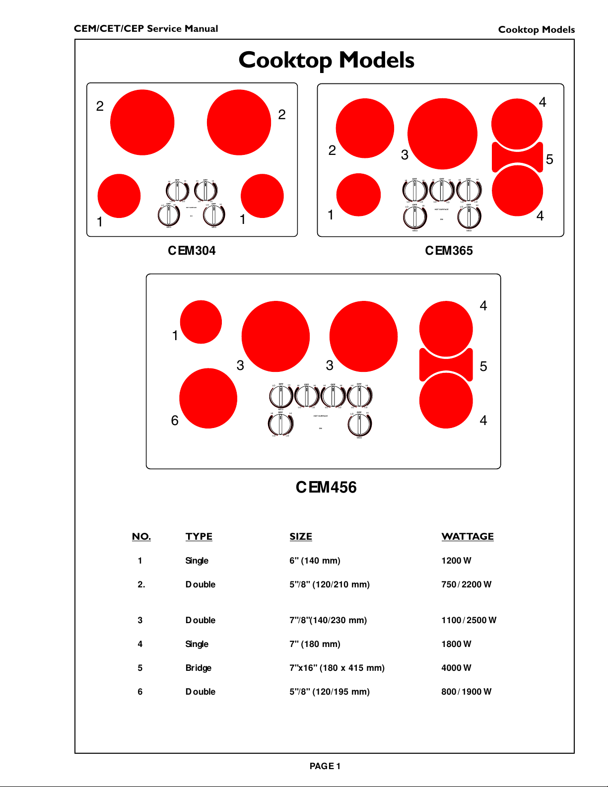
Cooktop Models.............................................. 1 - 2
CEM Cooktops ....................................................... 3
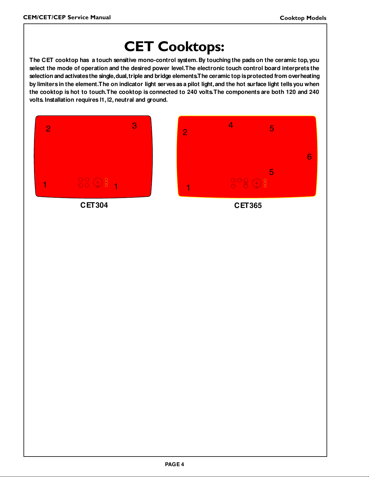
CET C ooktops: ....................................................... 4
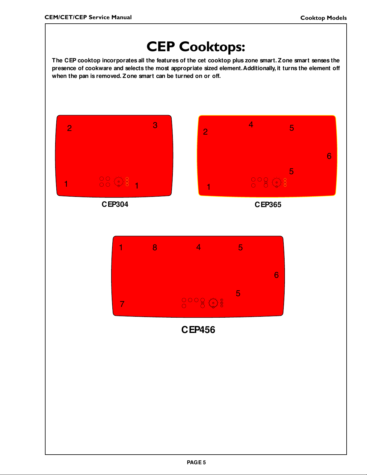
CEP Cooktops: ....................................................... 5
Ceramic C ooktop Technical O verview ............. 6
Technical O verview ................................................ 6
Component D escription ....................................... 7
Radiant Elements .................................................... 7
Component D escription ....................................... 7
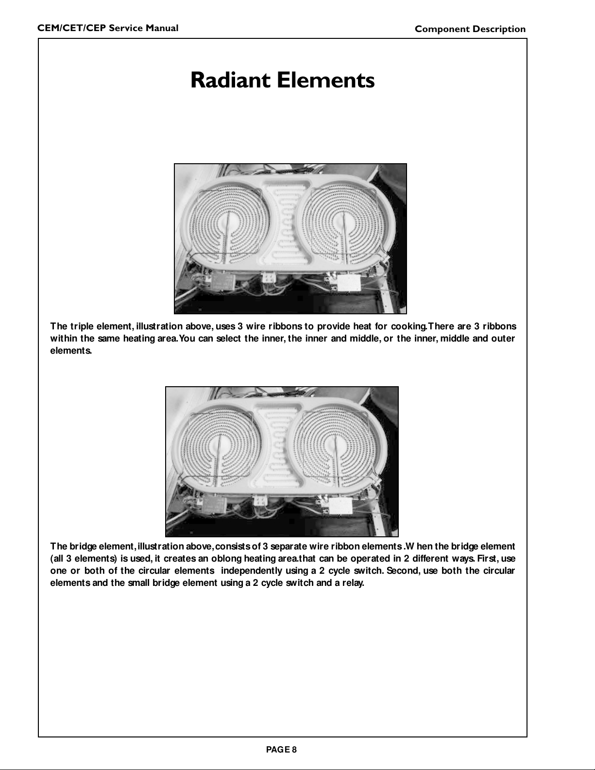
Radiant Elements .................................................... 8
Component D escription ....................................... 8
Infinite Switches ...................................................... 9
Component D escription ....................................... 9
Relay board ........................................................... 10
Component D escription .................................... 10
Temperature limiters .......................................... 11
Component D escription .................................... 11
Indicator lights...................................................... 12
Indicator LIGH TS ................................................ 12
Component D escription .................................... 12
Sensors:.................................................................. 13
Component D escription .................................... 13
Pot Sensing Circuit Board.................................. 14
Component D escription .................................... 14
ElectronicTouch Control Board ...................... 15
Component D escription .................................... 15
Relay board ........................................................... 16
Component D escription .................................... 16
Input board............................................................ 17
Component D escription .................................... 17
Installation ............................................................. 18
CEM Cooktops Installation ....................... 18 - 21
CET/CEP Cooktops Installation ............... 22 - 25
Cooktop D isassembly ................................ 26 - 32
Cooktop Reassembly.................................. 33 - 34
Technical D ata - Table of Errors ....................... 34
CET/C EP Residual H eat on Time ..................... 35
Pot Sensing Calibration .............................. 36 - 39
W iring and Visuals ....................................... 40 - 69
Electrical Schematic D rawings.................. 70 - 74
CET/CEP 365 ........................................................ 70
CET/CEP 304 ........................................................ 71
CEM 456 ................................................................ 72
CEM 304 ................................................................ 73
CEM 365 ................................................................ 74
https://appliancetechmanuals.com

CEM/CET/CEP Service Manual
PAGE 1
Cooktop Models
NO.TYPE SIZE WATTAGE
1 Single 6" (140 mm) 1200 W
2. D ouble 5"/8" (120/210 mm) 750
/
2200 W
3 D ouble 7"/8"(140/230 mm) 1100
/
2500 W
4 Single 7" (180 mm) 1800 W
5 Bridge 7"x16" (180 x 415 mm) 4000 W
6 D ouble 5"/8" (120/195 mm) 800
/
1900 W
MED MED
HI
HI
LO
LO
OFF
HI
LO OFF
HI
LO OFF
HI
HI
LO
LO
OFF
HOT SURFACE
ON
LO
MED MED
HI
LO
OFF
HI
OFF
HI
HI
LO
LO
OFF
HI
HI
LO
LO
OFF
HI
HI
LO
LO
OFF
HOT SURFACE
ON
HI
LO
MED
OFF
HI
OFF
HI
HI
LO
LO
OFF
LO
LO MED
HI
LO OFF
HI
HI
LO
LO
OFF HI
HI
LO
LO
OFF
HI
HOT SURFACE
ON
CEM456
CEM304 CEM365
2
1
2
11
235
4
4
1
6
35
4
4
3
Cooktop Models
https://appliancetechmanuals.com

CEM/CET/CEP Service Manual
PAGE 2
Cooktop Models
PAN
SIZE
ZONE
SMART™
PANEL
LOCK
POWER
19
8
7
6
5
4
3
2
KEEP
WARM
19
8
7
6
5
4
3
2
KEEP
WARM
PAN
SIZE
ZONE
SMART™
PANEL
LOCK
POWER
19
8
7
6
5
4
3
2
KEEP
WARM
PAN
SIZE
ZONE
SMART™
PANEL
LOCK
POWER
CEP456
CET304
CEP304
CET365
CEP365
2
1
3
11
245
5
6
1
7
45
5
6
8
NO.TYPE SIZE WATTAGE
1 Single 6" (140 mm) 1200 W
2. D ouble 5"/8" (120/210 mm) 750
/
2200 W
3 Triple 5"/7"/8"(120/175/210 mm) 800
/
1600
/
2300 W
4 Triple 5"/7"/9" (120/180/230 mm) 800
/
1600
/
2500 W
5 Single 7" (180 mm) 1800 W
6 Bridge 7"x16" (180 x 415 mm) 4000 W
7 D ouble 5"/8" (120/195 mm) 800
/
1900 W
8 D ouble 6"/9" (140/230 mm) 1100
/
2500 W
Models CET 304 and CET365 do not have the ZONE SMART™‘ Pad.
Cooktop Models
https://appliancetechmanuals.com

CEM/CET/CEP Service Manual
PAGE 3
MED MED
HI
HI
LO
LO
OFF
HI
LO OFF
HI
LO OFF
HI
HI
LO
LO
OFF
HOT SURFACE
ON
LO
MED MED
HI
LO
OFF
HI
OFF
HI
HI
LO
LO
OFF
HI
HI
LO
LO
OFF
HI
HI
LO
LO
OFF
HOT SURFACE
ON
HI
LO
MED
OFF
HI
OFF
HI
HI
LO
LO
OFF
LO
LO MED
HI
LO OFF
HI
HI
LO
LO
OFF HI
HI
LO
LO
OFF
HI
HOT SURFACE
ON
CEM456
CEM304 CEM365
2
1
2
11
235
4
4
1
6
35
4
4
3
CEM Cooktops
The CEM cooktops are mechanical models with a ceramic top and control knobs.The single radiant elements
are controlled by the 1-cycle infinite switches.The dual elements are controlled by the 2-cycle infinite switches.
The bridge element is controlled by a 2-cycle infinite switch and a relay (together they serve as a gang switch).
The ceramic isprotected ftom overheatingby limiters in the element.The O N indicator light servesas a pilot
light, and the hot surface light tells you when the surface is hot to touch.The cooktop is connected to 240
volts.All components are activated by 240 volts.There is no neutral line, only l1, l2, and ground.
Cooktop Models
https://appliancetechmanuals.com

CEM/CET/CEP Service Manual
PAGE 4
CET Cooktops:
The CET cooktop has a touch sensitive mono-control system. By touching the pads on the ceramic top, you
select the mode of operation and the desired power level.The electronic touch control board interprets the
selection and activatesthe single,dual,triple and bridge elements.The ceramic top isprotected from overheating
by limiters in the element.The on indicator light serves as a pilot light, and the hot surface light tells you when
the cooktop is hot to touch.The cooktop is connected to 240 volts.The components are both 120 and 240
volts. Installation requires l1, l2, neutral and ground.
PAN
SIZE
ZONE
SMART™
PANEL
LOCK
POWER
19
8
7
6
5
4
3
2
KEEP
WARM
19
8
7
6
5
4
3
2
KEEP
WARM
PAN
SIZE
ZONE
SMART™
PANEL
LOCK
POWER
CET304 CET365
2
1
3
11
245
5
6
Cooktop Models
https://appliancetechmanuals.com

CEM/CET/CEP Service Manual
PAGE 5
CEP Cooktops:
The CEP cooktop incorporates all the features of the cet cooktop plus zone smart. Zone smart senses the
presence of cookware and selects the most appropriate sized element.Additionally, it turns the element off
when the pan is removed. Z one smart can be turned on or off.
PAN
SIZE
ZONE
SMART™
PANEL
LOCK
POWER
19
8
7
6
5
4
3
2
KEEP
WARM
19
8
7
6
5
4
3
2
KEEP
WARM
PAN
SIZE
ZONE
SMART™
PANEL
LOCK
POWER
19
8
7
6
5
4
3
2
KEEP
WARM
PAN
SIZE
ZONE
SMART™
PANEL
LOCK
POWER
CEP456
CEP304 CEP365
2
1
3
11
245
5
6
1
7
45
5
6
8
Cooktop Models
https://appliancetechmanuals.com

CEM/CET/CEP Service Manual
PAGE 6
Ceramic CooktopTechnical Overview
The CEM/CET/CEP cooktops are comprised of the
following components:
Radiant Elements
Single Elements
D ual Elements
Triple Elements
Radiant Bridge Elements
Infinite Switches
1-Cycle
2-Cycle
Control Knobs
Relay Board
ElectronicTouch Control Relay Board
Pot Sensing Circuit Board
Heat Limiters
Sensors
Indicator lights
O N Indicator Light
Hot Surface Indicator Lights
Panel Lock Light
Power Light
Technical Overview
https://appliancetechmanuals.com

CEM/CET/CEP Service Manual
PAGE 7
Component Description
Radiant Elements
A single element, illustration above, uses a wire ribbon that is located under the glass ceramic surface to
provide the heat for cooking.The single element uses 1 wire ribbon. Radiant elements are designed to cycle
on and off.
The dual element, illustration above, uses 2 wire ribbons to provide heat for cooking.There are 2 ribbons
within the same heating area. Either the small inner element or both the inner and outer elements may be
selected for use.
Component Description
https://appliancetechmanuals.com

CEM/CET/CEP Service Manual
PAGE 8
The triple element, illustration above, uses 3 wire ribbons to provide heat for cooking.There are 3 ribbons
within the same heating area.You can select the inner, the inner and middle, or the inner, middle and outer
elements.
The bridge element,illustration above,consists of 3 separate wire ribbon elements .W hen the bridge element
(all 3 elements) is used, it creates an oblong heating area.that can be operated in 2 different ways. First, use
one or both of the circular elements independently using a 2 cycle switch. Second, use both the circular
elements and the small bridge element using a 2 cycle switch and a relay.
Radiant Elements
Component Description
https://appliancetechmanuals.com

CEM/CET/CEP Service Manual
PAGE 9
Infinite Switches
There is 2 types of infinite switches. 1-cycle, and 2 cycle. The 1-cycle infinite switch controls the single
element. The 1-cycle has an infinite number of heat settings between the low and high positions. D etents are
found at low and high to define minimum and maximan heat settings. Both switches are push and turn to
activate. To turn on the single switch, push down on the control knob and turn clockwise following the single
line graphics. (See illustrations, below)
The 2 -ycle infinite switch controls dual elements.The 2-cycle switch has an infinite number of heat settings
between the low and high positions. D etents are found at the low and high positions to define minimumand
maximum settings.To turn on the small,inner element,push down on the knob and turn in counter clockwise
following the single line graphic. (see illustration).
To turn on the bridge element,push down and turn the right rear knob clockwise to any heat settingbetween
low and high.The right front, right rear, and bridge elements will come on.To turn on the right rear element,
push down and turn the knob counter-clock wise to any heat setting between low and high.To turn on the
right front element, push down and turn the right front knob in eighter direction to any heat setting.
1-Cycle Switch 2-Cycle Switch
Component Description
https://appliancetechmanuals.com

CEM/CET/CEP Service Manual
PAGE 10
Relay board
A relay board and a 2-cycle infinite switch are used to operate the bridge elements.The bridge element
(4000 watts) draws 16 amps at full capacity.The 2-cycle infinite switch is rated at about 10 amps.The relay is
wired in series with the infinite switch and the bridge element. W hen the infinite switch cycles, it sends
current to the relay.As the relay contacts open and close, the bridge element is energized. ((See illustration,
below.)
Component Description
https://appliancetechmanuals.com

CEM/CET/CEP Service Manual
PAGE 11
Temperature limiters
Each element uses a temperature limiter to prevent the element from becoming too hot.The limiters have
2 sets of contacts, one is normally open, and one is normally closed.The normally open contact closes and
turns on the hot surface light when the glass is too hot to touch.The normally closed contacts control the
amount of heat to the cooktop by switching on and off, depending on the switch setting.Although cycling is
normal, the following can cause the limiter to cycle on and off more than usual (See illustration, below.)
• W arped or uneven pan bottoms not making full contact with the base.
• Pan is too small for the size of the element.
• Pan has boiled dry.
• Pan material or shape of the pan is slow to transfer heat.
Limiter
Component Description
https://appliancetechmanuals.com

CEM/CET/CEP Service Manual
PAGE 12
INDICATOR LIGHTS
PAN
SIZE
PANEL
LOCK
POWER
19
8
7
6
5
4
3
2
KEEP
WARM
The element “O N ” indicator light
Hot indicator lights
HH
H
Indicator lights
There are two indicator lights on the ceramic cooktops.
The O N indicator light turns on whenever any element is turned on. The light remains on until all the
elements are turned off. (see illustration)
Each element features a hot indicator light circuit to show when the cooking surface is too hot to touch.
After the element isturned off,an“h” will appear in the element display.the light remains on until the cooking
area has cooled to a safe to touch temperature. (see illustration)
Component Description
https://appliancetechmanuals.com

CEM/CET/CEP Service Manual
PAGE 13
Sensors:
O n CEP models the sensors detect pan sensing and pan sizing.
Pan sensing: The CEP models have sensors under the glass that detects if there is a metallic pan sitting on
the element.The element will not heat if it is turned on without a pan present, or if the pan is removed from
the element when it is operating. If no pan is present on the element, a beep will sound at 60 seconds.After
10 minutes, the cooktop beeps and shuts down if no pan is placed on the element.
Pan sizing: O n the double and triple elements, the sensor can choose the size pan being used and turn on
the appropriate element.This feature is either on or off for all elements, and works together with the pan
sensing feature. (See illustration, below.)
Pan sensing/sizing guidelines:
• O nly metal cookware will work with the pan sensing/pan sizing feature.GLASS OR STONEWARE WILL
NOT WORK.
• A pan must be sitting on the element for the element to heat up.
• O nly pans with flat metal bases can be detected.
• The bottom diameter of the pan must be at least as large as the diameter of the element. (Cookware
diameter indicated by the manufacturer is measured across the top and can be greater than the bottom).
• Center the cookware on the element.
• A large pan cannot exceed beyond 1" over the sides of the largest element.
Sensor
➝
Component Description
https://appliancetechmanuals.com

CEM/CET/CEP Service Manual
PAGE 14
Pot Sensing Circuit Board
The pot sensing circuit board works with the electronic touch control board to sense the presence and the
size of a pan on the burner.
Heres how it works:
The input board sends a signal to the sensor in each of the elements.W hen a pan is placed on the element,the
sensor sends a signal back to the input board.The signal tells the board the presence and size of the pan..
Component Description
https://appliancetechmanuals.com

CEM/CET/CEP Service Manual
PAGE 15
ElectronicTouch Control Board
The electronic touch control board is a microproccessor based control. It is comprised of 2 components, an
input board,and a relay board.These 2 components are fastened together with stand off clips.There is a mylar
sheet sandwiched between the 2 components.These 2 components communicate with each other through a
zif (zero insertion force) connector.
(see illustration)
Relay
board
Input
board
Mylar
sheet
➝
➝
➝
Illustration shows board separated
Component Description
https://appliancetechmanuals.com

CEM/CET/CEP Service Manual
PAGE 16
Relay board
The relay board has snap relays, a step down transformer, a microproccessor chip and several zenner diodes.
The stepdown transformer receives 120 v.a.c. and steps it down to 12 v.a.c..The zenner diodes rectify the 12
v.a.c. to 12 v.d.c to activate the 12 v.d.c snap relays.The relay board is commanded by the input board. Upon
command, the snap relays close and transfer line voltage to the elements. (See illustration, below.)
Illustrastion shows boards fastened together.
Component Description
https://appliancetechmanuals.com

CEM/CET/CEP Service Manual
PAGE 17
Input board
The input board has three functions. First, it accepts mode and setting selections by the user. Second, it
commands the relay board to perform the selected functions.And third, it outputs a signal voltage circuit to
the element sensors to determine the presence of a pan ,and the size of the pan.The input board is not glued
to the ceramic top. It is located in the rough in box below the ceramic glass.There are conductive bellows
between the board and the ceramic glass to provide continuity (see illustration).
Voltage isconstantly applied to the relay board.The voltage creates an electro-magnetic field around the input
board.W hen the user touchesthe ceramic glass and makesa selection,the circuit isinterupted.Thisinteruption
is interpreted by the microproccessor chip and the board is commanded according to the selection made by
the user. (see illustration).
O n units with the pot sensing/pot sizing feature, the board sends a signal voltage to each sensor in the
elements.W hen a pan is put on the burner, the sensor sends a signal back to the input board.The signal tells
the input board the presence of a pan and the size of a pan.
Ziff Connector
➝
➝
Connector for
Pot Sensor
Circuit Board
Component Description
https://appliancetechmanuals.com

CEM/CET/CEP Service Manual
PAGE 18
Cooktop Installation
Installation
CEM Cooktops
OVERALL DIMENSIONS A
See Illustration A, Page 2. These dimensions are
overall.
POWER SUPPLY B
ELECTRICAL POWER CONNECTION
FOR COOKTOP
Power Supply is dual rated: 240 Volts or 208 Volts, 3
wire, 60 Hz, with the following circuit breaker
requirements:
Model CEM304 at 30 Amps; Model
CEM365 at 40 Amps or Model CEM456 at 50 Amps
Install a junction box (not supplied), below the
counter top within 3 feet of flexible conduit (supplied)
located at the right rear corner of the cooktop rough-
in box.
JUNCTION BOX LOCATION D
Plan the installation of the unit so that the location
of the junction box is within 3 feet of the right rear
of the cooktop bottom.It must be accessible from
the front of the cabinet. (An exception to this
location would be for a cooktop installation over a
single electric oven In that situation, refer to Pages 4
and 5 and Figures I, J, K and L.
CABINET PREPARATION AND
CLEARANCES
To eliminate the risk of burns or fire by reaching
over heated surface units, cabinet storage space
located above the surface units should be avoided. If
cabinet storage is to be provided, the risk can be
reduced by installing a range hood that projects
horizontally a minimum of 5 in. (127 mm) beyond
the bottom of the cabinets. See C, Page 2.
This unit is designed for installation in the counter
top with zero clearance to adjacent walls and
projecting surfaces constructed of combustible
materials.A 30- inch minimum clearance is required
between the top of the cooktop and the bottom of
an unprotected cabinet. A 24 inch minimum distance
is necessary when the bottom of the wood or metal
cabinet is protected by not less than 1/4 inch of a
flame retardant material covered with not less than
N o. 28 MSG sheet steel, 0.015 inch (0.4 mm) thick
C
stainless steel,0.024 inch (0.6 mm) aluminum,or 0.020
inch (0.5 mm) thick copper.Flame retardant materials
bear the mark:
UN D ERW RITERS LABO RATO RIES IN C.
CLASSIFIED
MIN ERAL AN D FIBER BO ARD S
SURFACE BURN IN G CH ARACTERISTICS
Followed by the flame spread and smoke ratings.,
these designations are shown as “FHC (Flame
Spread)/(Smoke D eveloped)”. Materials with “O ”
flame spread ratings are flame retardant. Local codes
may allow other flame spread ratings.
The minimum horizontal clearance from the sides
and back edge of the cooktop to the adjacent vertical
combustible walls is 0 Inches.
COUNTERTOP CUTOUT
DIMENSIONS
The cutout dimensions depend upon whether the
installation is for replacement, new construction, or
installation in a solid surface countertop material,such
asSurell™ ,Corian®etc.These materialsrequire larger
cutouts, use of heat reflective tape and rounded
corners. D rawings Gand Hprovide some guidelines
only (see Page 4). Always consult the countertop
manufacturer for specific Installation Instructions.
E
https://appliancetechmanuals.com
This manual suits for next models
7
Table of contents
Popular Cooktop manuals by other brands

Whirlpool
Whirlpool 30" (76.2 cm) Electric Built-in Ceramic... installation instructions

Jenn-Air
Jenn-Air 8112P341-60 user guide

Kenmore
Kenmore 79075722991 installation instructions

emerio
emerio HP-114482.4 instruction manual

Schweigen
Schweigen INID77 instruction manual

Kenmore
Kenmore 911.93729 Use Use, care, safety manual

KitchenAid
KitchenAid KECC056RBL00 parts list

Frigidaire
Frigidaire FGB33WHSB Wiring diagram

Fisher & Paykel
Fisher & Paykel CG905DLPX1 Guidelines

Electrolux
Electrolux GAS COOKTOP Use and care guide

Fisher & Paykel
Fisher & Paykel GC901 Series Service manual

Fisher & Paykel
Fisher & Paykel CI302DTB installation instructions