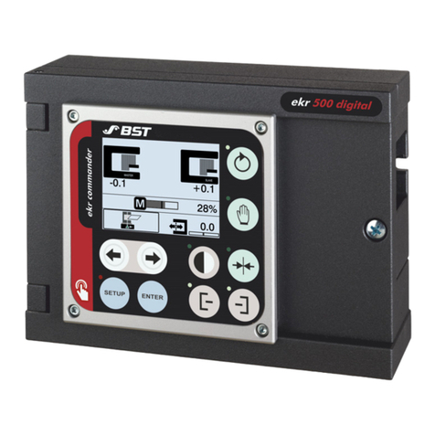
BST ekr 500 User manual

ekr 500 web guiding controller EDV No.: MD.299.01.06
with removable control panel Issue: 29.07.2008
ekr 500
Web guiding controller
with removable control panel
Operating Manual
BST International GmbH
Heidsieker Heide 53
33739 Bielefeld, Germany
Phone: +49 5206/999 – 0
Telefax: +49 5206/999 – 999
E-Mail: [email protected]
The information and drawings contained in this document are the property of BST International GmbH. Any reproduction
of this document as a whole or in part without the written permission of BST International GmbH is prohibited.

Content 0
ekr 500 web guiding controller EDV No.: MD.299.01.06
with removable control panel Issue: 29.07.2008
Content
1Description 1
1.1 Symbols used in this manual 1
1.1.1 Warning signs 1
1.1.2 Using the keys 1
1.1.3 LED operating status indications 1
1.2 General 2
1.3 Intended use 3
1.4 System description 4
1.4.1 System structure 4
1.4.2 Functional principle 5
1.4.3 Connectable components 5
1.5 Terms used 6
1.5.1 Set position 6
1.5.2 Sensor 1 / Sensor 2 7
1.6 Control panel 8
1.6.1 Graphical display 8
1.6.2 Control panel 8
1.7 Safety information 10
1.8 ESD protection 12
1.9 Emissions 12
1.10 RoHS conformity 12
2Technical Data 13
2.1 Controller 13
2.1.1 Ambient conditions 13
2.1.2 Protection class 13
2.1.3 Power supply (terminal strip X6) 13
2.1.4 Analogue inputs (terminal strip X1, X2, X3) 13
2.1.5 Digital inputs (terminal strip X14) 14
2.1.6 Ouput motor output stage (terminal strip X7) 14
2.1.7 Output fault relay (terminal strip X10) 14
2.1.8 Control panel interface (terminal strip X8) 15
2.1.9 Weight, dimensions 15
2.2 Control panel 16
2.2.1 Ambient conditions 16
2.2.2 Protection class 16
2.2.3 Power supply 16
2.2.4 Display 16
2.2.5 Weight, dimensions 16
2.3 Sensors 18
2.3.1 Infrared sensors 18
2.3.2 Ultrasonic sensors 18
2.4 Electric-motor-driven actuators 19
2.5 Power pack 20
3Transport 21
3.1 Transport 21
3.2 Storage 21
4Assembly 22
4.1 Installation site requirements 22
4.2 Assembly of the controller 23
4.2.1 General 23
4.2.2 Mounting plan 23
4.2.3 Space needed to open the enclosure cover 23
4.2.4 Mounting 24
4.2.5 Turning the control panel 25

Content 0
ekr 500 web guiding controller EDV No.: MD.299.01.06
with removable control panel Issue: 29.07.2008
4.3 Assembly of the control panel 26
4.3.1 General 26
4.3.2 Wall mounting 27
4.3.3 Control console mounting 29
5Installation 31
5.1 General 31
5.2 Fitting the cable connections 31
5.3 Installation instructions for EMC-wiring 32
5.4 Overview processor board 33
5.5 Terminal assignment 34
5.5.1 Terminal overview 34
5.5.2 Terminal assignment 35
5.5.3 Plug assignments 38
5.6 Set DIL switches 40
5.6.1 DIL switch S4 40
5.6.2 DIL switch S5 41
5.7 Service indications 42
5.7.1 LEDs “Bus status” 42
5.7.2 LEDs “Device status“ 42
5.7.3 LEDs “Power supply“ 43
5.7.4 LEDs “Controller interlock“/ “OK signal“ 43
5.7.5 LEDs “Remote control“ 43
6Start-up 44
6.1 Start-up actuator 44
6.1.1 General 44
6.1.2 Determine sense of motor rotation 45
6.1.3 Determine guiding direction 45
6.1.4 Actuator without position feedback
(EMS 5 / 10 / 16) 46
6.1.5 Actuator with position feedback
(EMS 17, EMS 21, EMS 22) 48
6.2 Carry out material setup 52
6.3 Adjustment of gain 53
6.4 Start-up electronic remote precision adjustment (option) 54
7Operation 55
7.1 Operation display 55
7.1.1 Basic display 55
7.1.2 Special displays 56
7.2 Material Setup 60
7.2.1 General 60
7.2.2 Activate material setup 61
7.2.3 Procedure for web edge guiding 62
7.2.4 Procedure for web center-line guiding 64
7.3 Operating mode selection 68
7.3.1 Manual positioning 68
7.3.2 Automatic guiding 68
7.3.3 Center positioning 68
7.4 Setting the web set point 69
7.5 Optimise gain 71
7.6 Display of system information 72
7.7 Electronic remote precision adjustment (option) 73
8Remote control 74

Content 0
ekr 500 web guiding controller EDV No.: MD.299.01.06
with removable control panel Issue: 29.07.2008
9Default settings 75
9.1 Device addresses 75
9.1.1 Device address of the controller 75
9.1.2 Device address of the control panel 76
9.2 Keyboard bus terminating resistors 77
9.2.1 Controller terminating resistor 77
9.2.2 Control panel terminating resistor 78
9.3 Generating the default settings 79
10 Trouble shooting 80
11 Maintenance 84
11.1 General 84
11.2 Controller 84
11.3 Control panel 84
11.4 Sensors 85
11.5 Electric-motor-driven actuator 85
12 Decommissioning 86
I Index
A1 Annex 1 A1
Connecting plan

Description 1
12
ekr 500 web guiding controller EDV No.: MD.299.01.06 Chapter: 1
with removable control panel Date: 29.07.08 Page: 1/86
1 Description
1.1 Symbols used
in this manual
1.1.1 Warning signs Symbols are used in this operating manual in order to clearly
indicate particularly important places.
Attention!
You must obey this type of warning, in order to protect
yourself, as the operator, from bodily injuries arising
from mechanical movements.
Beware!
You must obey by this type of warning without fail, in
order to protect yourself, as the operator, from life
threatening injuries caused by electrical voltages.
Note
This symbol is used to point out additional useful tips,
which will help you to make optimum use of all of the
functions.
1.1.2 Using the keys Using the keys is represented by the following symbols in this
manual:
Press key.
Key combinations, keys have to be
pressed simultaneously.
1.1.3 LED operating status
indications Some keys on the control panel have LED’s (light-emitting diodes)
integrated in them. The different LED operating states are
represented as follows:
LED off
LED constantly lit = activated phase
LED flashing
!

Description 1
12
ekr 500 web guiding controller EDV No.: MD.299.01.06 Chapter: 1
with removable control panel Date: 29.07.08 Page: 2/86
1.2 General
The start-up, maintenance and installation
instructions described in this operating manual
must be strictly adhered to!
•The ekr 500 web guiding controller must be mounted and
operated only according to the knowledge of the relevant
operating manual.
This will help avoiding hazards and preventing damages to the
controller caused by improper assembly or operation.
•This operating manual, and particularly the safety instructions
must be observed by all persons working on or with the ekr 500
controller.
•Before operating the system for the first time as well as
before carrying out maintenance work you must read the
safety information provided by chapter 1.7 of this manual!
•Changing or loading firmware on this system must be carried
out exclusively by BST personnel or personnel duely
authorised to do so by BST. Non observance of this may
cause the loss of the warranty rights!
•The values and data shown in this manual (e. g. in the display)
are to be considered as examples, unless otherwise expressly
stated.
•The current version of the operating manual for the web guiding
controller ekr 500 in all available languages can be found on the
Internet at the following address:
http://www.bst-international.com
!

Description 1
12
ekr 500 web guiding controller EDV No.: MD.299.01.06 Chapter: 1
with removable control panel Date: 29.07.08 Page: 3/86
1.3 Intended use The ekr 500 is a microprocessor-controlled web guiding controller
with removable control panel. It may be used for
•web edge guiding
(guiding to the right or left web edge)
•web center-line guiding
The web guiding controller ekr 500 has been designed to be
installed in another machine or to be integrated with other
machines to form a single system in compliance with directive
98/37/EU (Machinery Directive).
It is forbidden to commission the system until the user/operator has
determined that the machine in which the system has been
installed, complies with the specifications given in this directive.
You are only allowed to use BST web guiding systems to correct
the position of web-shaped materials (e.g. those made from paper,
film, cardboard, rubber, etc.).
The controller and the control panel must never be installed in
potentially explosive areas.
Operation is only guaranteed if carried out using the BST web
guiding components listed in chapter 1.4.3 (“Connectable
components“).
BST web guiding systems have been designed and built in
accordance with state-of-the-art standards and the recognized
safety rules.
Nevertheless, its use may constitute a risk to life and limb of the
user or of third parties or damage the BST web guiding systems
and other equipment.
Therefore BST web guiding systems are only to be used if they are
working correctly and in a safe technical condition. Any part found
to be working incorrectly must be replaced immediately.
Only original spare parts are to be used for this. Spare parts
obtained from third parties cannot be guaranteed to comply with
the design and manufacturing conditions and safety regulations.
In this case any guarantee claims made against the BST web
guiding system will be invalidated.
Only qualified personnel who have been trained on the system are
allowed to undertake any work required on the BST web guiding
system (i.e. installation, commissioning, operation, maintenance, etc.).
Intended use also includes adhering to the instructions given in this
operating manual.
Using the machine for purposes other than those mentioned above
is contrary to its intended use. BST International GmbH does not
accept liability for any damage resulting from this type of use.

Description 1
12
ekr 500 web guiding controller EDV No.: MD.299.01.06 Chapter: 1
with removable control panel Date: 29.07.08 Page: 4/86
1.4 System description
1.4.1 System structure
1.4.1.1 General
The ekr 500 consists of the controller and the removable control
panel.
The controller enclosure contains all of the control electronics and
the connections for all of the necessary web guiding components
(sensors, actuator, servo center transducer, remote control).
1.4.1.2 Controller with mounted
control panel
Controller operation is carried out via the control panel that was
attached to the front of the controller in the factory.
Controller with mounted control panel
1.4.1.3 Controller with removed
control panel
If the installation requires a remote mounting of the control panel
due to space or access limits in the machine, it can be removed
und remotely mounted in the machine operator control station.
In this case the connection between the controller and control
panel is made using a cable extension that is available as an
optional extra.
Controller with removed control panel
The length of the cable used to connect the control
panel to the controller must never exceed 20 m.
Cable extension
(2 m, 5 m, 10 m)
Controller Control panel

Description 1
12
ekr 500 web guiding controller EDV No.: MD.299.01.06 Chapter: 1
with removable control panel Date: 29.07.08 Page: 5/86
1.4.2 Functional principle In automatic mode one or two edge sensors connected to the
controller scan the actual position of the web of material and
transmit this information to the position controller.
The position controller compares the actual position measured
against the required set position. If there is a difference between
the two values then the controller transmits a correction signal to
the actuator of the guiding device.
The actuator moves the guiding device (rotating frame guide or
swivel roll guide) until the web of material is in its set position again.
1.4.3 Connectable components The picture shows the components that can be connected to the
controller.
Controlle
r
ekr 500
A
ctuator without
position feedback
A
ctuator with
position feedback
EMS 5, EMS 10, EMS 16
Servo-cente
r
transducer
Remote control, keyboard lock
OK signal
Analogue edge sensors
IR 2001
IR 2002
IR 2005
US 2003
US 2007
US 2008
US 2009
24 V DC
Controller with
removed control
p
anel
OMG 4,
OMG 8
EMS 17,
EMS 21,
EMS 22
EFE 1 EFE 1000
Electronic remote precision adjustment
— optional —

Description 1
12
ekr 500 web guiding controller EDV No.: MD.299.01.06 Chapter: 1
with removable control panel Date: 29.07.08 Page: 6/86
1.5 Terms used
1.5.1 Set position The set position is the required position for the web of material in
the sensor scanning area. It can be set up in “Automatic“ mode
using the control panel arrow keys (see chapter 7.4).
The set position setting will be marked on the control panel display
by a white triangle being superimposed around the sensor symbol.
The relative coverage of the sensor scanning area will be
displayed as a percentage beneath the sensor symbol.
Examples:
0% covering
No material within
the sensor scanning area.
50% covering
Only one half of the sensor
scanning area is covered.
100% covering
Sensor scanning area is fully
covered.
Deviation between
set and actual position
Set position = Actual position
Center of
sensor scanning area
Relative coverage of the
sensor scanning area
Sensor scanning area Web of material

Description 1
12
ekr 500 web guiding controller EDV No.: MD.299.01.06 Chapter: 1
with removable control panel Date: 29.07.08 Page: 7/86
1.5.2 Sensor 1 / Sensor 2 In this operating manual, the sensors that are connected to the
controller are designated with “sensor 1“ and “sensor 2“.
According to the BST definition, the following link applies between
the selection buttons for the guiding mode and the sensors:
= Sensor 1 (left web edge)
= Sensor 2 (right web edge)
The following is valid in respect of the sensor mounting positions:
The sensor, which is located to the left of the material in the
web running direction (when looking from the material top
side), is sensor 1.
The material top side is the side of the material web which is not in
direct contact with the deflection pulleys of the guiding device.
Example 1: Example 2: Example 3:
As standard, sensor 1 must be connected to terminal strip X1,
while sensor 2 must be connected to terminal strip X2 of the
controller (see terminal assignments, chapter 5.5).
Sensor 1
Sensor 2
Sensor 1 Sensor 2
Sensor 1
Sensor 2
Pivot Deflection pulley
Guiding device

Description 1
12
ekr 500 web guiding controller EDV No.: MD.299.01.06 Chapter: 1
with removable control panel Date: 29.07.08 Page: 8/86
1.6 Control panel
The control panel contains all of the operating and display controls
needed to operate the web guiding system.
The signal settings on the controller’s remote
control inputs block any keys on the control panel
that have counter functions.
1.6.1 Graphical display The different operating statuses and all the relevant control
parameters are displayed on the control panel’s graphics display
during operation.
The symbol significances are described in chapter 7.1.
1.6.2 Control panel Located on the control panel are four different key groups that
have the following functions:
Green keys: Operating mode selection
Grey keys: Guiding mode selection
Blue keys: Setup mode
White keys: Manual positioning of the guiding device,
Guiding setpoint and gain adjustment,
Changing of parameter values
You will find the separate key significances listed in the table on
the following page.

Description 1
12
ekr 500 web guiding controller EDV No.: MD.299.01.06 Chapter: 1
with removable control panel Date: 29.07.08 Page: 9/86
Function Key Designation Description
Automatic
Automatic web guiding
Manual mode Manual positioning
of the guiding device
Operating mode
selection
Servo-center Center positioning
of the guiding device
Sensor 1
Guiding to the left web edge
Sensor 2
Guiding to the right web edge
Guiding mode
selection
Web center-line guiding
Manual positioning
of the guiding
device
Arrow key
left / right
Operating mode “Manual“:
•Manual positioning of the guiding
device to the left/right
Shifting of the
guiding setpoint
Arrow key
left / right
Operating mode “Automatic“:
•Shifting of the guiding setpoint
to the left/right
SETUP
Operating mode “Manual“:
•Call up setup selection menu
Operating mode “Automatic“:
•Activate gain adjustment
ENTER •Store value
and exit setup mode
Setup mode
Arrow key •Decrease/increase
parameter value

Description 1
12
ekr 500 web guiding controller EDV No.: MD.299.01.06 Chapter: 1
with removable control panel Date: 29.07.08 Page: 10/86
1.7 Safety information The safety relevant information in accordance with DIN EN 294,
DIN EN 349 and the industry specific safety regulations must be
taken into consideration when installing the BST equipment in the
production machine, these include:
•There must be a safe distance between the BST equipment and
the machinery already installed on-site, such as machine
panels, building structure, etc.
•Connection lines between the individual system components
must be laid so that nobody can trip over them, not pulled tight
and well anchored down.
•Ensure that there is sufficient free headroom.
If the height of free passage is restricted, the relevant building
components causing the restrictions must be padded and a
danger warning signs must be attached to them (yellow/black).
•As a matter of course, cable connectors (e. g. between
controller and sensors) should only be disconnected when the
system is no longer connected to the mains supply (mains plug
has been removed). Any infringements will result in the
warranty claim being invalidated.
•In principle, the controller does not have ATEX certification, i.e.
you are not permitted to use it in area where the danger of an
explosion exists!
•Any transport safety devices that were used must be removed
prior to commissioning.
Only trained specialist personnel are permitted to
undertake the assembly, installation and
commissioning!
Danger of cuts!
Never touch the edges of moving webs of material!
Danger of crushing!
Never reach inbetween the fixed lower frame and the
moving upper frame of the guiding device (rotating
frame guide or swivel roll guide).
Never reach into the moving rolls!
!
!
!

Description 1
12
ekr 500 web guiding controller EDV No.: MD.299.01.06 Chapter: 1
with removable control panel Date: 29.07.08 Page: 11/86
Please do not open the controller until the line voltage
is switched off.
When operation at open unit is necessary, only
protection class IP 20 is present.
There will be an increased risk of danger by line
voltage!
Before starting work, ensure the equipment is
electrically isolated. To this end always carry out the
following measures:
1. Switch off.
2. Prevent switching back on.
3. Check the equipment is isolated.
4. Earth.
5. Cover or shield any adjacent parts that are still live.
Only then you can carry out the relevant work.
Please do not use the guiding frame as a tread or a
Stepp ladder.
Do not remove any safety devices.
Positioning movements will be undertaken by the
actuator during functional testing away from the
production machine and/or during the commissioning!
The relevant safety arrangements must be
implemented during performance checks!
Monitor the overall safety concept of the production
machine during commissioning!
!
!

Description 1
12
ekr 500 web guiding controller EDV No.: MD.299.01.06 Chapter: 1
with removable control panel Date: 29.07.08 Page: 12/86
1.8 ESD protection
Attention!
Hazards caused by electrostatic discharge
(ESD = Electro Static Discharge).
The device contains components which can be damaged by
electrostatic discharge. This component can receive permanent
damage, which can lead to loss of performance, failure or destruction
of the part, if it contacts electrostatically-charged persons or objects.
System component housings may only be opened at an ESD-
protecting workplace (ESD workplace in accordance with
DIN EN 61340-5-1). If there is no ESD-protected workplace
available, ESD precautionary measures in accordance with
DIN EN 61340-5-1 must be taken to ensure that electrostatic
charges are carefully discharged.
If making return shipments of electronic components or assemblies,
regulations in accordance with DIN EN 100 015 “Protection of
electrostatically-endangered components“ must be observed.
You should therefore only use the electrically conductive ESD
packaging provided for transport, and label it correctly.
BST International GmbH is not liable for any damages caused
by the nonobservance of the ESD protective measures
described here.
1.9 Emissions The A-related equivalent continuous sound level of the equipment
is less than 70 dB(A).
1.10 RoHS conformity We hereby declare that the ekr 500 web guiding controller does not
exceed the hazardous substance limits stipulated in EU Directive
2002/95/EU*.
* EU Directive for restricting the use of specific hazardous
substances used in electrical and electronic equipment,
“RoHS Directive“ (Restriction of Hazardous Substances).

Technical Data 2
8
ekr 500 web guiding controller EDV No.: MD.299.01.06 Chapter: 2
with removable control panel Date: 29.07.08 Page: 13/86
2 Technical Data
2.1 Controller
2.1.1 Ambient conditions Environment temperature
in operation: 0 ... 45°C
Storage temperature: - 10°C ... + 70°C
Air humidity in operation: 5 ... 90%, without condensing
2.1.2 Protection class Protection class: IP 54
(considering the installation site
requirements, see chapter 4.1)
2.1.3 Power supply
(terminal strip X6) Voltage: 24 V DC ± 10% (including ripple)
Power consumption: max. 4 A (including actuator)
Connection: plugged in from the outside using a
3-pin plug as per CEN 175301-803
(DIN 43650)
2.1.4 Analogue inputs
(terminal strip X1, X2, X3) Sensors (terminal strip X1, X2)
Signal input sensor 1/2: 0 ... 10 V, ± 10 V or 0 ... 20 mA
(selectable via DIL switch)
Power supply: ± 12 V ± 5%
< 50 mA (+12 V)
< -50 mA (-12 V)
+24 V DC / max. Σ0,5 A
IR pulses: for IR 2001, IR 2002, IR 2005
+5 V (length ≈250 µs)
Connection: internal on cage clamp
Position feedback EMS 17/21/22, servo-center transducer OMG 4,
remote precision adjustment EFE 1 (terminal strip X3)
Signal input: ± 10 V
Power supply: ± 12 V
Connection: internal on cage clamp
Maximum power supply max. Σ+12 V: 150 mA
(X1 + X2 + X3) max. Σ-12 V: 100 mA

Technical Data 2
8
ekr 500 web guiding controller EDV No.: MD.299.01.06 Chapter: 2
with removable control panel Date: 29.07.08 Page: 14/86
Servo-center transducer OMG 8 (terminal strip X10)
Signal input: according to Namur specification
Power supply: according to Namur specification
Connection: internal on cage clamp
2.1.5 Digital inputs
(terminal strip X14) Remote control, remote
precision adjustment EFE 1000: < 4 V (Low), > 8 V (High)
(terminal 74 – 81)
Controller interlock: < 4 V (Low), > 8 V (High)
Switched via the hardware, i.e. not
via the processor or the software.
Galvanic isolation: none!
Connection: internal on cage clamp
2.1.6 Ouput motor output stage
(terminal strip X7) Voltage: ± 24 V DC
(reduces the actuator’s maximum
actuating force if a lower supply
voltage is used)
Power consumption: max. 1.2 A (peak current 4 A)
Protection: Automatic electric switching off
after approx. 400 ms if overcurrent
occurs with motor current in one
direction (no polarity change):
> 1.9 A (EMS 21, EMS 22)
> 1.1 A (EMS 10, EMS 16, EMS 17)
> 0.4 A (EMS 5)
Connection: internal on cage clamp
2.1.7 Output fault relay
(terminal strip X10) Voltage: max. +24 V AC/DC
Power consumption: max. 1 A
Connection: internal on cage clamp

Technical Data 2
8
ekr 500 web guiding controller EDV No.: MD.299.01.06 Chapter: 2
with removable control panel Date: 29.07.08 Page: 15/86
2.1.8 Control panel interface
(terminal strip X8) Voltage: + 24 V DC
(corresponds to the supply voltage)
Power consumption: max. 0.5 A
(protected by Polyfuse)
Bus interface: 500 kBaud,
no galvanic isolation
Connection: plugged in from the outside using a
4-pin micro style M8 connector
2.1.9 Weight, dimensions Weight: approx. 1.18 kg
(controller without control panel)
Dimensions: See page 17

Technical Data 2
8
ekr 500 web guiding controller EDV No.: MD.299.01.06 Chapter: 2
with removable control panel Date: 29.07.08 Page: 16/86
2.2 Control panel
2.2.1 Ambient conditions Environment temperature
in operation: 0 ... 45°C
Storage temperature: - 10°C ... + 70°C
Air humidity in operation: 5 ... 90%, without condensing
Protection class: IP 54
2.2.2 Protection class Protection class: IP 50
If the controller is installed with
mounted control panel the whole
unit is classed as protection class
IP 54.
2.2.3 Power supply Voltage: + 24 V DC
(power supplied by the controller)
2.2.4 Display Resolution: 128 x 64 pixel,
LED background illumination
2.2.5 Weight, dimensions Weight: approx. 0.26 kg
Dimensions: See page 17
Other manuals for ekr 500
5
Table of contents
Other BST Controllers manuals
Popular Controllers manuals by other brands
G.T. Attuatori
G.T. Attuatori GTX Series Installation, operation & maintenance manual
AUMA
AUMA GST 10.1 Operation & instruction manual
Honeywell
Honeywell HEGSA002 User manual user manual
zeeltronic
zeeltronic PCDI-RGT user manual
NetApp
NetApp E Series manual
GRAIGAR
GRAIGAR R448 Installation and Maintenance
