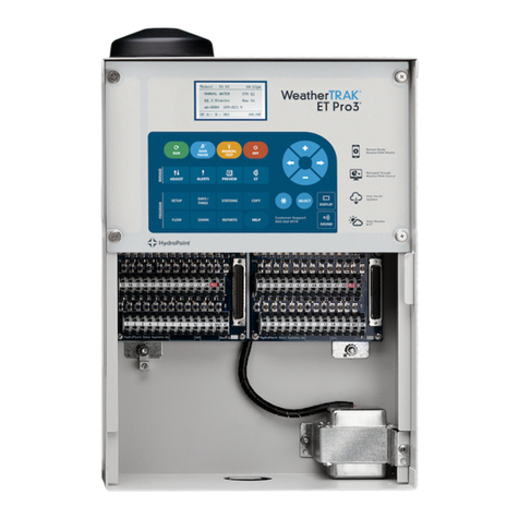
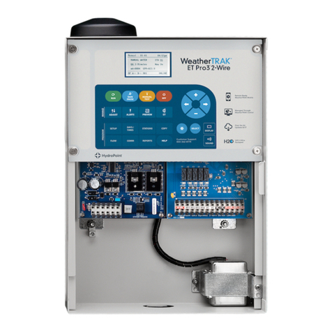
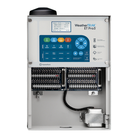
HydroPoint WeatherTRAK 2-Wire User manual

Questions? Contact Customer Support at [email protected]
Installation Guide
Included in Guide:
•2-Wire System Overview
•Installation Procedure
•Grounding
•Testing
© Copyright 2020 HydroPoint Data Systems, Inc.
WeatherTRAK 2-Wire Controller
Featuring H2O Technology

WeatherTRAK 2-Wire Controller Installation Guide
1
©2020 HydroPoint Data Systems Inc. All rights reserved. 800.362.8774 • hydropoint.com
CONTENTS
Overview ...........................................................................................................................................................3
Introduction....................................................................................................................................................3
How
does
the
WeatherTRAK
2-wire
controller
work?
.....................................................................................3
The Five Components....................................................................................................................................3
WeatherTRAK 2-Wire Devices........................................................................................................................4
Total Supported Devices and Limits...............................................................................................................4
Maximum Concurrent Valves ......................................................................................................................5
Wire Specifications.........................................................................................................................................6
Connecting Devices to the Spring Clamp Terminals ......................................................................................6
LED Light System........................................................................................................................................8
2-Wire Status LED lights .............................................................................................................................8
Hardware Installation
.......................................................................................................................................10
Installation Procedure ......................................................................................................................................10
Step
1 —
Install
the
WeatherTRAK
2-Wire
Controller
...................................................................................11
A. Mount the Enclosure: Wall Mounting Instructions.........................................................................11
B. Connect the Controller to AC Power..............................................................................................12
C. Insert Station Keys if Applicable.....................................................................................................13
D. Connect a Flow Sensor (if applicable) ............................................................................................ 13
E. Install a Rain Switch (if applicable) .....................................................................................................14
Step 2 — Assign Each Decoder to a Station ................................................................................................17
Assigning a Single Valve Decoder to a Station .........................................................................................18
Assigning a Dual Valve Decoder to a Station............................................................................................19
Assigning a Master Valve, Flow Sensor or Pump Start Decoder................................................................ 20
Reassigning a Decoder .............................................................................................................................21
Programming a Direct Connect Master Valve ...........................................................................................23
Programming a Direct Connect Flow Sensor ............................................................................................24
Step 3
—
Install Valve Decoders onto the 2-Wire Path.................................................................................. 25
Best Practices............................................................................................................................................26
Step 4 — Ground the System.......................................................................................................................28
Using the Line Surge Arrestor...................................................................................................................28
Step
5
—
Connect the
Two
-
‐
Wire
Path
to
the
Controller
...............................................................................30
Step 6 —
Configure the 2
-
‐
Wire
on
the
WeatherTRAK
Control Panel
.............................................................30
WeatherTRAK 2-Wire Controller Installation Guide
2
©2020 HydroPoint Data Systems Inc. All rights reserved. 800.362.8774 • hydropoint.com
Step 7 — Program the Stations and Activate the Controller ........................................................................31
Step 8 — Test the System ............................................................................................................................31
Running a Valve Test ................................................................................................................................31
Manually Testing the Stations...................................................................................................................31
Manual Test by Individual Station .............................................................................................................31
Manual Test for All Stations ......................................................................................................................31
Manual Test by Program...........................................................................................................................32
Viewing Decoder Information ...................................................................................................................32
Viewing Electrical Information for Stations and Valves..............................................................................32
Troubleshooting ..............................................................................................................................................34
Standard Power and Current Readings
......................................................................................................34
Installed Decoders: Serial Numbers and Associated Stations Worksheet ........................................................36

WeatherTRAK 2-Wire Controller Installation Guide
3
©2020 HydroPoint Data Systems Inc. All rights reserved. 800.362.8774 • hydropoint.com
Overview
Introduction
WeatherTRAK 2-wire controllers provide the simplicity of 2-wire control with the proven water savings,
automation and central visibility and control you expect from commercial WeatherTRAK solutions.
How
does
the
WeatherTRAK
2-wire
controller
work?
WeatherTRAK 2-wire controllers use a 2-wire path with decoder devices that connect with irrigation valves to
perform irrigation functions. All valves are connected to decoders that can either manage a single valve or
decoders that can manage multiple valves. The result is a streamlined configuration that enables the system
to operate efficiently while minimizing the amount of materials needed to complete the job.
The Five Components
There are five major components to the WeatherTRAK 2-wire control system: the controller, the 2-wire path,
the decoders, the accessories and the surge arrestors.
The WeatherTRAK 2-wire controller
The WeatherTRAK 2-wire controller is the main terminal point for all 2
-
‐
wire paths as well as direct wire
master valves and flow sensors.
The 2-wire path
The 2
-
‐
wire path carries the power and control signals from the controller to the decoders and devices in the
field.
Valve Decoders
A valve decoder is installed at each valve solenoid and connected to the 2
-
‐
wire path. The decoder acts as a
switching device that turns a valve on and off with a signal from the controller. Decoders are usually installed
at the valve they control, in the same valve box. Valve decoders are available in two configurations: single
valve decoders and dual valve decoders. A dual valve decoder can manage two valves independently which
saves on material costs and installation time.
Two-Wire Accessories
The WeatherTRAK 2-wire platform includes multiple 2-wire accessories that perform various flow management
related tasks. The 2-wire accessories include a master valve decoder, a flow sensor decoder, and a pump start
decoder.
Surge Arrestors
Surge arrestors are installed at regular intervals along the 2
-
‐
wire path and connected to a ground rod at
each ground point. S
urge arrestors are usually installed at the beginning and end of the 2-wire path, and
after every 600 feet.

WeatherTRAK 2-Wire Controller Installation Guide
4
©2020 HydroPoint Data Systems Inc. All rights reserved. 800.362.8774 • hydropoint.com
WeatherTRAK 2-Wire Devices
The WeatherTRAK 2-wire controller can communicate with all of the following HydroPoint 2-wire devices:
•Single and dual valve decoders
•Flow sensor decoders
•Master valve decoders
•Pump start decoders
Total Supported Devices and Limits
The following table lists the total numbers of devices by type that can be connected to a WeatherTRAK 2-wire
controller. The WeatherTRAK 2-wire controller can support up to 110 device loads on the 2-wire path within
the layout and length limits outlined later in this section. A device load indicates the amount of electricity
required to sufficiently power the decoder.
Note: The device load requirements change between decoder types.
The load value/rating for each 2-wire device is shown in the table below.
Two-Wire Device Type Total Device Loads Milliamps
Valve decoder (one and two valve)
96
½ per decoder
0.5mA
Master valve decoder 4 ½ per decoder 0.5mA
Flow sensor decoder
4
3
Varies
Pump start decoder 4 ½ per decoder 0.5mA
NOTE: Limits for Release 7.10.x and 8.6.x of the WeatherTRAK 2-wire Controller:
•96 Stations
•Total of 4 Master Valves (mix of 2-wire and Direct Connect)
•Total of 4 Flow Sensors (mix of 2-wire and Direct Connect)
•4 Pump Start Decoders (each pump start decoder reduces maximum number of stations by 1)
NOTE: Unused ports or serial numbers on decoders that do not occupy a station address do not count
towards the maximum station count.

WeatherTRAK 2-Wire Controller Installation Guide
5
©2020 HydroPoint Data Systems Inc. All rights reserved. 800.362.8774 • hydropoint.com
Maximum Concurrent Valves
The maximum number of concurrently operating valves is shown in the two tables below. The number of
concurrent valves varies based on the total load count and wire length to the farthest device:
Decoder and Sensor Load Count
Maximum Concurrent Valves -#12 Wire
Wire Length (ft)
1000-3000
4000
5000
6000
7000
8000
100
15
14
13
8
6
4
90 15 15 14 9 7 5
80
15
15
15
10
8
6
70 15 15 15 11 9 7
60
15
15
15
12
10
8
50 15 15 15 13 11 9
40
15
15
15
14
12
10
30 15 15 15 15 13 11
20
15
15
15
15
14
12
10 15 15 15 15 15 13
Decoder and Sensor Load Count
Maximum Concurrent Valves -#14 Wire
Wire Length (ft)
1000
2000
3000
4000
5000
100 13 11 8 4 2
90
14
12
9
5
3
80
15
12
10
6
4
70
15
13
11
7
5
60
15
14
12
8
6
50
15
15
13
9
7
40
15
15
14
10
8
30 15 15 15 11 9
20
15
15
15
12
10
10 15 15 15 13 11

WeatherTRAK 2-Wire Controller Installation Guide
6
©2020 HydroPoint Data Systems Inc. All rights reserved. 800.362.8774 • hydropoint.com
Wire Specifications
Use the following recommended wire.
Wire Size: 12 or 14 AWG
Construction: Special irrigation control wire
Conductor: 2 same gauge solid core conductors conforming to ASTM B-33, B-3, or B-8
Insulation: Polyvinyl Chloride (PVC) conforming to UL-493 or UL-719 for thermo-plastic-insulated style UF
(underground feeder)
Outer Jacket: Low density, high molecular weight polyethylene (PE) with a thickness of 0.045”
Temperature: 60°C (140°F)
Voltage: 600 volts RMS max
Example of approved wire:
Coleman Cable #51452
Paige P7072D, P7296D, P7350D, and P7354D
Regency 14/2 and 12/2 Maxi Cable, Toro Decoder Cable, and Hunter Decoder Jacketed Service Wire
DEC12/2BE and DEC14/2BE.
Connecting Devices to the Spring Clamp Terminals
The chassis board inside the enclosure has the following spring clamp terminals:
Two-Wire Direct Connect Terminals
1 24VAC terminal
4 Master Valve terminals
4 Flow Sensor terminals
4 Common terminals
Two-Wire Connection and programming Terminals
3 2-Wire connection terminals
1 decoder station programming push release terminal
Other Terminals
3 Station Key ports
1 input rain sensor
1 Main 24VAC terminal

WeatherTRAK 2-Wire Controller Installation Guide
7
©2020 HydroPoint Data Systems Inc. All rights reserved. 800.362.8774 • hydropoint.com
The diagram below shows where the terminals, connections and other parts are located.

WeatherTRAK 2-Wire Controller Installation Guide
8
©2020 HydroPoint Data Systems Inc. All rights reserved. 800.362.8774 • hydropoint.com
LED Light System
WeatherTRAK 2-wire controllers use an LED diagnostic light system to help with troubleshooting issues that
may arise. Remove the controller front panel to completely reveal the valve and terminal boards.
2-Wire Status LED lights
The 2-wire status LED lights turn red when an issue is encountered. In a normal, functioning state the lights
remain off. Below is as chart explaining what each light means when illuminated or blinking:
ELE
Electrical Alert: could indicate a valve issue
FLO
Flow Alert
COM Indicates no communication with server
Blinking: adapter board can’t communicate with controller
2-Wire Status Check 2-wire status on diagnostics screen
Blinking: adapter board bootloader is active
D42(not labeled)
Blinking: adaptor board is NOT communicating with OEM board
Flow 1,2,3,4, Blinking: flow pulses are currently detected (direct or 2-wire)
Chassis Diagram with LED light Indicators

WeatherTRAK 2-Wire Controller Installation Guide
9
©2020 HydroPoint Data Systems Inc. All rights reserved. 800.362.8774 • hydropoint.com
Use the chassis diagram to identify each of the six LED diagnostic lights on the controller chassis and check to
see if each is illuminated. Then, compare results to the diagnostic table below and take appropriate action.

WeatherTRAK 2-Wire Controller Installation Guide
10
©2020 HydroPoint Data Systems Inc. All rights reserved. 800.362.8774 • hydropoint.com
Hardware Installation
Installation Procedure
The drawing below shows a typical two path wiring scenario with a master valve. The master valve can either
be installed on the 2
-
‐
wire path or directly to the WeatherTRAK 2-wire controller using a conventional wiring
approach.

WeatherTRAK 2-Wire Controller Installation Guide
11
©2020 HydroPoint Data Systems Inc. All rights reserved. 800.362.8774 • hydropoint.com
Step
1 —
Install
the
WeatherTRAK
2-Wire
Controller
Mount, electrically install and ground the WeatherTRAK 2-Wire Controller. Specifications can be found on
our Product Details and Documentation page under Design Specifications for the ET Pro3 and the OptiFlow
Controllers.
All installations should comply with local and national electrical codes. Failure to ground and install the
controller properly will void the warranty.
A.
Mount the Enclosure: Wall Mounting Instructions
Use the enclosed template for assistance when mounting the enclosure to a wall. (see example)
Locate the 2 mounting holes on the back of the enclosure. The two upper mounting holes are keyholes. This
design allows the two upper fasteners to be installed first. The enclosure is then slipped over and pushed
down to complete the installation.
A third mounting hole can be found in the center of the enclosure below the station input/output board.
Typical mounting height for a wall-mount enclosure is between 41” and 48” above a finished surface.
Example of Wall Mount Drilling Template
Before drilling, verify that the controller is level and vertically straight before installing.
Remove the outer door for access to the interior of the enclosure. Slide it upwards, then place it in a
location to prevent damage.
Mark and drill new mounting holes using the paper template, then drill appropriately sized holes with a
hammer-drill as needed. Use plastic inserts and mounting screws (taped to the controller with the
enclosure keys) to secure the controller.
Hang the enclosure on these fasteners and verify the enclosure is mounted level both vertically and
horizontally.
Locate the third center mounting hole and insert the last fastener. Tighten all fasteners to the enclosure to
secure to the vertical surface.

WeatherTRAK 2-Wire Controller Installation Guide
12
©2020 HydroPoint Data Systems Inc. All rights reserved. 800.362.8774 • hydropoint.com
B. Connect the Controller to AC Power
WARNING! Before making a connection to your WeatherTRAK 2-wire controller, disconnect the power to
avoid electric shock. This installation should be made by a qualified electrician and should meet state and
local electrical codes.
The WeatherTRAK ET Pro 3 2-wire controller incorporates a dual voltage power supply for a wide range of
commercial applications. The controller can be connected to a single phase 120 VAC or single phase 220
VAC source.
The following wiring diagrams and instructions indicate AC power connections to both wall-mount and
pedestal style controllers.
The input side of the transformer has 5 color-coded conductors. A label is attached to the transformer body
with identification for each conductor. Two of the conductors (specific to 220 VAC connections) have been
terminated with wire nuts, shortened and tied together with a zip-tie to avoid confusion for 120 VAC
installations.
•For 120 VAC wire applications, connect the following conductors from the primary side of the transformer
to wiring from an approved electrical source (see Typical 120 Volt Diagram). The unused blue and brown
wires are cut short and terminated with a wire nut.
•For 220 VAC, single-phase applications connect the following conductors from the primary side of the
transformer to wiring from an approved electrical source (see Typical 220 Volt Diagram).
Typical
120 Volt
Wiring Diagram.
Typical
220 Volt
Wiring Diagram
Note
: Secure each ground wire with its own individual
locking nut and integral star
washer. The Unused black and
bro
wn wires should be terminated with a wire nut
separately.
Note:
the unused blue and brown wires should be
terminated with a wire nut separately.

WeatherTRAK 2-Wire Controller Installation Guide
13
©2020 HydroPoint Data Systems Inc. All rights reserved. 800.362.8774 • hydropoint.com
Confirm the controller has been securely fastened to a flat, vertical surface before starting this work.
Open the enclosure door and locate the transformer mounted to the chassis. Thread an approved
weatherproof plastic or galvanized metal junction box onto the 1/2” nipple and secure with a conduit
locknut.
Connect approved conduit to the underside of the junction box.
Pull the required number of conductors and terminate them in the junction box with sufficient length
so that wire nut connections can be made.
Remove approximately 1/2” of the wire insulation of the conductor and use an appropriately sized wire
nut based on the number of wire connections being made. Adhere to local and state electrical codes.
The ground wire should be terminated with an appropriately sized eyelet (included on grounding stud)
and secured with a nut with the integral star washer located within the junction box (see Figure 8). The
unused blue and brown wires should be terminated with a wire nut separately.
C. Insert Station Keys if Applicable
The WeatherTRAK 2-wire controller incorporates station count modularity by using station keys. The station
input/output boards are available in two configurations, 0-48 and 48-96.
To increase the station count from 48-96 or higher, insert a station key into the station output board,
beginning with the slot to the far left (see figure below). The station key will illuminate when activated. The
controller will automatically discover the expanded station count within 30 seconds.
Increase Max Active Stations in the SETUP menu. For instructions, read
https://hydropointsupport.force.com/s/article/Setting-the-Maximum-Active-Stations
D. Connect a Flow Sensor (if applicable)
The WeatherTRAK 2-wire controller is compatible with WeatherTRAK Flow3, WeatherTRAK FlowHD, Data
Industrial (Badger Meter) IR 220 series, Creative Sensor Technology and Netafim (using reed switch registers)
irrigation flow sensors. Flow sensors can connect from the 2-wire path, or directly to the mini-chassis on the
controller.

WeatherTRAK 2-Wire Controller Installation Guide
14
©2020 HydroPoint Data Systems Inc. All rights reserved. 800.362.8774 • hydropoint.com
To connect a flow sensor directly, read:
Programming a Direct Connect Flow Sensor.
To connect a flow sensor from the 2-wire path, read:
Assigning a Master Valve, Flow Sensor or Pump Start Decoder.
E. Install a Rain Switch (if applicable)
The WeatherTRAK 2-wire controller is compatible with normally closed wired or wireless rain or rain/freeze
switches. One rain switch can be shared with multiple controllers on a site. A dedicated 24 VAC output and
Rain Sensor input terminal block is available on the terminal board (see terminal board diagram). The terminal
block can be removed for faster and easier field installation. It is keyed to fit only one-way to avoid cross-
connection. The 24 VAC terminals are not polarized and wire can be terminated in either terminal as needed
when 24 VAC power is required.
Note: When a wireless rain switch is used with a metal enclosure, install the rain sensor receiver outside the
enclosure to ensure reception from a remotely mounted rain switch transmitter. Do not install a wireless rain
switch within metal enclosures where signal strength is diminished.
Irritrol Wireless Rain Switch Installation
Mount the rain switch receiver where it can be easily accessed and observed.
For wall-mount installations, route the receiver wires through the bottom of the enclosure into the interior
of the enclosure. Deburr any field drilled through holes and insert a ¼” inside diameter rubber grommet
to protect field wiring. Add a small amount of silicone sealant where the sensor wire enters the grommet
for added protection.
Warning! Avoid shorting wires from an open thru-hole without a grommet. A shorted wire can cause
permanent damage to the controller electronics, an issue not covered under warranty.

WeatherTRAK 2-Wire Controller Installation Guide
15
©2020 HydroPoint Data Systems Inc. All rights reserved. 800.362.8774 • hydropoint.com
Locate the rain sensor input terminal block in the upper-left corner of the 24-station input/output board.
This terminal block is designed to be removable to facilitate faster connection of rain sensor wiring. To
remove, simply wiggle the terminal block side to side. Remove the rain switch wire jumper (See figure
below).
Remove approximately 3/8” of wire insulation to expose the solid or stranded conductor.
Confirm the lever of the screwless terminal is in the up or unlocked position. Insert the exposed wire and
press the lever downward to lock. Confirm contact by gently pulling down on the inserted wire.
Connect the red wires to the 24 VAC terminals to red colored terminals. These terminals are not polarized;
either wire can be inserted into either of the two far left terminal positions.
Insert the white wire into the white colored terminal and the brown wire into the black colored terminal as
shown in Figure 10. Confirm the lever has not clamped down on the wire insulation which can result in
electrical continuity and operation of the rain switch.
Locate the rain switch transmitter within the manufacturer’s recommended range. Locate the transmitter
where it will receive rainfall without obstruction. Confirm communication to the receiver before mounting
permanently.

WeatherTRAK 2-Wire Controller Installation Guide
16
©2020 HydroPoint Data Systems Inc. All rights reserved. 800.362.8774 • hydropoint.com
Test the rain sensor function by pressing the test switch on top of the transmitter for a brief period of time.
Confirm the controller displays “RainSwitch” in the RUN menu when the test switch is depressed.
Note: For other compatible rain switch wiring diagrams, please read the manufacturer’s instructions for
normally closed rain switches.
Center Drill Points for Rain Sensor Mounting
The bottom left and right outer sides of the enclosure have two sets of drilling center points as shown below.
These drilling points are for enclosure mounting for specific Irritrol or Toro wireless or wired rain or rain/freeze
sensors. Two self- tapping stainless steel screws are taped to the inside of the enclosure to mount a rain
sensor receiver when needed.
Note: Mount the rain sensor receiver on the opposite side of the transformer location to avoid reception
issues for wireless models.
Irritrol Wireless Rain Switch Series

WeatherTRAK 2-Wire Controller Installation Guide
17
©2020 HydroPoint Data Systems Inc. All rights reserved. 800.362.8774 • hydropoint.com
Step 2 — Assign Each Decoder to a Station
After you have installed the WeatherTRAK 2-wire controller, you will need to assign the decoders to a station
so the controller can find these stations in the field and activate the valve.
Valve decoders can be pre-assigned through HydroPoint before shipment. If the decoder is pre-assigned, you
will see a sticker on the decoder and you will not need to assign it before installation.
If the decoder is not pre-assigned, you will need to assign it to a station using the station program terminal
located on the mini-chassis. (#8 in chassis illustration)
When assigning stations to a 2-valve decoder (WT2W-H2O-2VD), the stations will need to be assigned in
sequence. For example, if you want to use a 2-valve decoder and your next stations to be assigned are
stations 34 and 35, they will need to be assigned in that order.
When assigning the decoders take note that the decoder has a unique serial number on its label. When you
assign the decoder to a station, the controller will recognize the serial number of the decoder and its
associated station(s). This will help with system troubleshooting and diagnostics.
Caution: The
WeatherTRAK
2-wire controller does not have a mechanism that prevents you
from
assigning
the
same
ID
to
several valve decoders. Consequently, we advise you to assume caution when
assigning IDs to the stations to minimize the risk of assigning identical station IDs. Creating identical stations
will likely overload the system and cause failures.
When you assign a decoder to a station, you plug the decoder into the Station Program push release terminal
located on the lower section of the mini chassis board. It is critical that polarity be maintained (red to red,
black to black).
The controller reads the decoder to find out what type of decoder it is. Then you assign the decoder to a
station, set the power level and complete the programming.
You can configure your system to include both direct wire and 2-wire management options. The 2-wire
current measurements are normalized to correspond with direct-wired solenoid values. This allows the user to
easily manage both direct and two wire connections to evaluate electrical current limits.
Note: When performing 2-wire detailed electrical diagnostics from the WeatherTRAK 2-wire control panel, the
current measurements will reflect actual inrush, holding and idle current.

WeatherTRAK 2-Wire Controller Installation Guide
18
©2020 HydroPoint Data Systems Inc. All rights reserved. 800.362.8774 • hydropoint.com
When assigning decoders, the display screen will look something like this:
Line 1
Setup: 15 10:42am
Line 2
ST01 ADDR1= 01
Line 3
TYPE=2.1 PWR=Low
Line 4
Press * to assign
----- -----
Line 1 shows the screen name/number and the current time.
Line 2 is the device ID and the decoder’s address assignment. In this example, the device is a valve decoder
on station number 01.
Line 3 is the decoder’s type and power level. In this example, the decoder is a single valve decoder. The PWR
level defaults to low.
Line 4 is the action you take to assign the decoder with an address that matches that station. In this example,
you would press the * button.
Navigation:
You use the buttons on the control panel to navigate through the screens when programming the decoders.
Below is a chart which explains each action.
To Exit press
To go back to start: Press
To take an action: Press *
To change the device ID or power level: press +or -
Assigning a Single Valve Decoder to a Station
Plug the decoder into the terminal located on the mini-chassis board.
Press SETUP.
Press until CONFIGURE H2O 2-WIRE displays (setup 15).
Press +or – until Program decoders displays.
Press SELECT.
Press *. The controller reads the decoder and assigns it to the next station in sequence. If you need to
change the station number, press + or –.
Press * to assign the decoder to the station shown.
Press +or – to set the power level. Power levels for each station can be adjusted independently. The
power defaults to low. For most stations, low power is sufficient.

WeatherTRAK 2-Wire Controller Installation Guide
19
©2020 HydroPoint Data Systems Inc. All rights reserved. 800.362.8774 • hydropoint.com
Press * to configure the decoder. The following screen displays, confirming a successful assignment:
Setup: 15 10:43am
PROGRAMMING SUCCESSFUL
Device ID: ST01 (Orange)
(Remember to label)
_____ _____
Note: The display screen will show the decoder wire color that is associated with each valve. The orange wire
is the valve wire.
Label the decoder then unplug it from the Station Program terminal.
To assign the next decoder, press . To exit, press .
Assigning a Dual Valve Decoder to a Station
A dual valve decoder is assigned in the same way that a single valve decoder is assigned; however, when
assigning a dual valve decoder, the stations will automatically assign in order of the next two stations in
sequence. The display screen when assigning a dual valve decoder will look something like this:
Setup: 15 10:43am
ST01 ADR = 01 02
TYPE: 2.2 PWR=Norm
Press * to assign
_____ _____
Plug the decoder into the terminal located on the mini-chassis board.
Press SETUP.
Press until CONFIGURE H2O 2-WIRE displays (setup 15).
Press +or – until Program decoders displays.
Press SELECT.
Press *. The controller reads the decoder and assigns it to the next two stations in sequence. If you need
to change the station number, press + or –.
Press * to assign the decoder to the stations shown.
Press +or – to set the power level. For a dual valve decoder, the power level for both valves is the same,
and cannot be different. Note that the power defaults to low. For most stations, low power is sufficient.
However, some stations may require more power due to a longer 2-wire path or a higher electrical
requirement for a specific valve type.
Table of contents
Other HydroPoint Controllers manuals

HydroPoint
HydroPoint WeatherTRAK LC Controller User manual

HydroPoint
HydroPoint WeatherTRAK ET Pro2 SWM User manual

HydroPoint
HydroPoint WeatherTRAK ET Pro3 2-Wire User manual

HydroPoint
HydroPoint WeatherTRAK ET Pro3 User manual

HydroPoint
HydroPoint WeatherTRAK ET Pro2 User manual

HydroPoint
HydroPoint WeatherTRAK ET Pro3 User manual

HydroPoint
HydroPoint WeatherTRAK Chassis 7 User manual