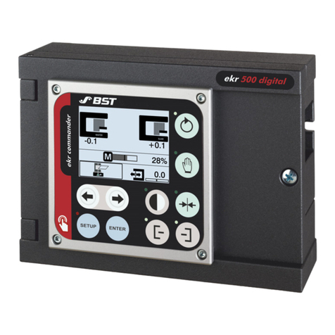
BST ekr 500 User manual

Web Guiding System
Installation and
Operating Manual
ekr 500 digital Unit Touch
Application with Wide Array Edge Sensors
MD.503.EN.01
Translation of the Original Manual

BST GmbH
Remusweg 1
D-33729 Bielefeld
Tel.: +49 (0) 521 400 70 0
Fax: +49 (0) 5206 999 999
E-Mail: [email protected]
Internet: www.bst.group
This documentation is protected by copyright. The translation as well as reproduction and distribution in any form is forbidden without the approval
of the rights holder and will be pursued under civil and criminal law. Technical modifications reserved.

Table of contents
ekr 500 digital Unit Touch – Application with Wide Array Edge Sensors iii
Table of contents
1 About This Document........................................................................................ 5
1.1 What You Need to Know............................................................................................... 5
1.2 Target Group................................................................................................................. 5
1.3 Storage and Distribution............................................................................................... 5
1.4 Meanings of the Safety Instructions and Symbols........................................................ 6
1.4.1 Safety Instructions ........................................................................................................ 6
1.4.2 Symbols......................................................................................................................... 6
1.4.3 Operation Using Keys.................................................................................................... 6
1.5 More Detailed Information........................................................................................... 7
2 About Safety ..................................................................................................... 8
2.1 Intended Use................................................................................................................. 8
2.2 Non-intended Use......................................................................................................... 8
2.3 Safety Instructions ........................................................................................................ 8
3 Design and Function.......................................................................................... 9
3.1 Components.................................................................................................................. 9
3.2 Design ........................................................................................................................... 9
3.3 Wide Array Edge Sensors............................................................................................ 10
3.3.1 Properties.................................................................................................................... 10
3.3.2 Sensor Types ............................................................................................................... 10
3.3.3 Measuring Range ........................................................................................................ 11
3.3.4 Indicator LED............................................................................................................... 12
3.4 Guiding Modes............................................................................................................ 13
4 Technical Specifications ...................................................................................14
4.1 Ultrasonic Wide Array Edge Sensors US SEN 300 ... 309............................................. 14
4.2 Infrared Wide Array Edge Sensors IR SEN 400 ... 409 ................................................. 16
4.3 Connection Box........................................................................................................... 18
5 Transport, Delivery and Storage .......................................................................19
5.1 Transport..................................................................................................................... 19
5.2 Scope of Delivery ........................................................................................................ 19
5.3 Unpacking the Delivery............................................................................................... 19
5.4 Storage........................................................................................................................ 19
6 Installation.......................................................................................................20
6.1 Safety Instructions ...................................................................................................... 20
6.2 Installing the Wide Array Edge Sensor........................................................................ 20
6.2.1 Selecting the Installation Location.............................................................................. 20
6.2.2 Installing the Wide Array Edge Sensor........................................................................ 21
6.3 Installing the Connection Box ..................................................................................... 22
6.3.1 Selecting the Installation Location.............................................................................. 22
6.3.2 Installing the Connection Box ..................................................................................... 22
7 Electrical Connection........................................................................................23
7.1 Safety Instructions ...................................................................................................... 23
7.2 Connecting the Wide Array Edge Sensor to the Controller ........................................ 24
7.3 Checking Correct Connection...................................................................................... 25
8 Commissioning.................................................................................................26
8.1 Safety Instructions ...................................................................................................... 26
8.2 Requirements.............................................................................................................. 27
8.3 Performing the Material Setup ................................................................................... 27
9 Operation ........................................................................................................28
9.1 Safety Instructions ...................................................................................................... 28
9.2 Operation Display ....................................................................................................... 28

Table of contents
iv ekr 500 digital Unit Touch – Application with Wide Array Edge Sensors
9.2.1 Operation Display Wide Array Edge Sensors (Sensor 1/2).......................................... 28
9.2.2 Symbol Meanings........................................................................................................ 30
9.2.3 Examples for the Display of the Edge Positions.......................................................... 31
9.2.4 Display with Loss of the Web Edge ............................................................................. 32
9.3 Performing the Material Setup ................................................................................... 32
9.3.1 Function ...................................................................................................................... 32
9.3.2 Performing the Material Setup ................................................................................... 33
10 Maintenance and Cleaning...............................................................................35
10.1 Safety Instructions ...................................................................................................... 35
10.2 Maintenance Table ..................................................................................................... 36
10.3 Maintenance and Cleaning work ................................................................................ 36
10.3.1 Cleaning the Wide Array Edge Sensor Housing........................................................... 36
11 Troubleshooting...............................................................................................37
12 Accessories and Spare Parts .............................................................................38
12.1 Order Address............................................................................................................. 38
12.2 Accessories.................................................................................................................. 38
Index................................................................................................................39

About This Document 1
ekr 500 digital Unit Touch – Application with Wide Array Edge Sensors 5/39
1 About This Document
1.1 What You Need to Know
These instructions describe the operation of the ekr 500 digital
Unit Touch web guiding controller in combination with ultrasonic
wide array edge sensors of type US SEN 300 … 309 and infrared
wide array edge sensors of type IRSEN400…409. They are a sup-
plement to the operating manual for the ekr 500 digital Unit
Touch controller (document number MD.492).
These instructions must only be used in conjunction with
the operating manual for the ekr 500 digital Unit Touch
web guiding controller. Every user must be familiar with
the installation and operating manual for the controller
and observe the safety instructions contained therein.
These supplementary instructions contain only information
required for the operation of the ekr 500 digital Unit Touch
controller with wide array edge sensors that is not already listed
in the operating manual for the controller.
The following instructions must be observed in order to avoid
hazards and incorrect operation:
■Every user must have read these instructions in full before
working with or on the system.
■Every user must follow the safety information in these instruc-
tions and in the operating manual for the ekr 500 digital Unit
Touch web guiding controller.
1.2 Target Group
These instructions are directed to all persons that work with or on
the system. The operating company of the entire system and
supervising personnel must also be familiar with these instructions.
1.3 Storage and Distribution
These instructions must be stored at the workplace in such a man-
ner that the user has access to them at all times.
These instructions and all other applicable documents are a com-
ponent of the product and must be handed over to the operating
company of the system.

1About This Document
6/39 ekr 500 digital Unit Touch – Application with Wide Array Edge Sensors
1.4 Meanings of the Safety Instructions and Symbols
1.4.1 Safety Instructions
DANGER
Danger that will lead to death or severe injuries!
►Here you can find how to avoid the danger.
WARNING
Danger that may lead to death or severe injuries!
►Here you can find how to avoid the danger.
CAUTION
Danger that may lead to medium or minor injuries!
►Here you can find how to avoid the danger.
NOTICE
Danger that may lead to damage to assets!
There is no risk of injury.
►Here you can find how to avoid the danger.
1.4.2 Symbols
Information that is essential for successful operation.
Information that makes operation easier.
Action requirements may include the following symbols:
›› Requirements that must be fulfilled for the action steps.
1. Requirement for you to take actions. And ...
2. …in the sequence specified.
►Requirement for you to take actions - without any certain
sequence.
1.4.3 Operation Using Keys
Operations using the keys are indicated by the following symbols:
►Press key ①.
►Press key ① or key ②.
►Press key ① and key ② at the same time.

About This Document 1
ekr 500 digital Unit Touch – Application with Wide Array Edge Sensors 7/39
1.5 More Detailed Information
►Observe the accompanying documents (e.g. order confirmation)
for this system and the operating instructions of the entire
system.
There are other documents available for this system.
Document Document number
Operating manual
ekr 500 digital Unit Touch MD.492
Installation and commissioning manual
ekr 500 digital Unit Touch MD.497
The latest version of these instructions can be obtained in all
available languages at:
www.bst.help

2About Safety
8/39 ekr 500 digital Unit Touch – Application with Wide Array Edge Sensors
2 About Safety
Please refer to the operating manual for the ekr 500 digital Unit
Touch web guiding controller (document number MD.492).
2.1 Intended Use
Combined with ultrasonic wide array edge sensors of type
US SEN 300 … 309 or infrared wide array edge sensors of type
IR SEN 400 … 409 the ekr 500 digital Unit Touch web guiding
controller is only determined for web guiding. It permits guiding
according to the web edges and the web center-line.
The system may only be used observing the operating manual for
the ekr 500 digital Unit Touch web guiding controller.
All information regarding safety as well as intended and non-
intended use listed there, also apply for the application of the web
guiding controller with wide array edge sensors.
2.2 Non-intended Use
For this web guiding system the same use is non-intended that is
described in the operating manual for the ekr 500 digital Unit
Touch controller.
2.3 Safety Instructions
Every user must read and follow the safety instructions in this
manual and in the operating manual for the ekr 500 digital Unit
Touch web guiding controller before working with or on the system.

Design and Function 3
ekr 500 digital Unit Touch – Application with Wide Array Edge Sensors 9/39
3 Design and Function
3.1 Components
A standard web guiding system with wide array edge sensors com-
prises the following components:
■One ekr 500 digital Unit Touch web guiding controller
■One or two ultrasonic or infrared wide array edge sensors
including connection box
■One guiding device (e.g. rotating frame guide)
■One actuator (integrated in the guiding device)
■One set of connecting cables
3.2 Design
Controller
ekr 500 digital Unit Touch
Connection box
CAN bus CAN bus
Wide array edge sensor 1 Wide array edge sensor 2
Connection box
X102 X103
Fig.1: ekr 500 digital Unit Touch controller with wide array edge sensors
The wide array edge sensors are connected to the CAN bus inter-
face of the controller as Sensor1 or Sensor2 using a special con-
nection box. The connection box is part of the scope of delivery.

3Design and Function
10/39 ekr 500 digital Unit Touch – Application with Wide Array Edge Sensors
3.3 Wide Array Edge Sensors
3.3.1 Properties
Wide array edge sensors are used in conjunction with the ekr 500
digital Unit Touch web guiding controller for contact-free scanning
of web edges.
The wide measuring range offers the following advantages:
■Scanning of two web edges with one sensor
■Scanning of webs of material with different widths without
changing the sensor position
3.3.2 Sensor Types
3.3.2.1 Ultrasonic Wide Array Edge Sensors US SEN 300 ... 309
Ultrasonic wide array edge sensors of type USSEN300…309 are
used for scanning the web edges of sound-impermeable materials
(e.g. paper, foil, …) or light sensitive materials. Scanning of the
web edges is carried out contact-free by ultrasonic waves.
Ultrasonic wide array edge sensors are available with two fork
widths (38 mm and 101 mm) and various measuring ranges
(30mm to 467mm) (see Ultrasonic Wide Array Edge Sensors US
SEN 300 ... 309, page 14).
3.3.2.2 Infrared Wide Array Edge Sensors IR SEN 400 ... 409
Infrared wide array edge sensors of type IR SEN 400 … 409 are
used for scanning the web edges of opaque materials such as non-
wovens or thick materials. Scanning of the web edges is carried
out contact-free by infrared light.
Infrared wide array edge sensors are available with two fork
widths (38 mm and 101 mm) and various measuring ranges
(30mm to 467mm) (see Infrared Wide Array Edge Sensors IR SEN
400 ... 409, page 16).

Design and Function 3
ekr 500 digital Unit Touch – Application with Wide Array Edge Sensors 11/39
3.3.3 Measuring Range
The measuring range of a wide array edge sensor is the range in
which the sensor detects web edges.
Transducer
Fork width
Measuring range
Web of material
Fig.2: Marking of the sensor measuring range
The measuring range is marked by the white lines on the housing
of the wide array edge sensor.
Web edges that should be detected by the sensor must
be located within the measuring range.
The web of material should be placed in the middle of the sensor
fork (in the middle between the two measuring transducers) for
optimum guiding results.

3Design and Function
12/39 ekr 500 digital Unit Touch – Application with Wide Array Edge Sensors
3.3.4 Indicator LED
The bicolour indicator LED in the housing shows how many edges
are detected by the wide array edge sensor.
Indicator LED
Fig.3: Indicator LED
Colour of
the LED
Signification
OFF
The sensor has detected no web edge.
RED
The sensor has detected one web edge.
GREEN
The sensor has detected two web edges.

Design and Function 3
ekr 500 digital Unit Touch – Application with Wide Array Edge Sensors 13/39
3.4 Guiding Modes
Combined with one or two wide array edge sensors, the ekr 500
digital Unit Touch controller permits the following guiding modes:
Guiding mode Key on the
controller
Basic principle
Web edge guiding
Guiding to the left web edge
Guiding to the right web edge
Guiding to the left web edge
Guiding to the right web edge
Web center-line
guiding
Web center-line guiding with two wide array edge sensors
Web center-line guiding with one wide array edge sensor

4Technical Specifications
14/39 ekr 500 digital Unit Touch – Application with Wide Array Edge Sensors
4 Technical Specifications
4.1 Ultrasonic Wide Array Edge Sensors US SEN 300 ... 309
USSEN…
300 301 302 303 304 305 306* 307 308* 309
Fork width 38
mm
101
mm
38
mm
101
mm
38
mm
101
mm
38
mm
101
mm
38
mm
101
mm
Measuring range 30mm 60mm 162mm 284mm 467mm
Min. web width 11mm
Linearity ≤ 0.3%
Supply voltage From the controller (24V⎓ ±10%)
Ultrasonic frequency 208kHz
Output signal BST CAN bus
Polarity reversal protection (supply) yes
Operation display LED (bicolour)
Electrical connection M8 plug, 4-pin (at the connection box)
Ambient temperature
during operation 0 to +75°C
Storage temperature 0 to +75°C
Protection category IP40
Noise emission <70dB
Housing dimensions See dimensional drawing
RoHS conformity yes
* in preparation

Technical Specifications 4
ekr 500 digital Unit Touch – Application with Wide Array Edge Sensors 15/39
Dimensions [mm]
= Fixing dimensions
Measuring range M
Center of measuring range
600 mm cable
(connection to the
connection box) Operating range
Fig.4: Dimensions of the ultrasonic wide array edge sensors US SEN 300 ... 309
Sensor Dimension
A B M O P T U W X Y Z
USSEN300 67 106 30 18
10
38 77 95 116
18 5
USSEN301 130 81 101 140
USSEN302 67 136 60 18 38 77 127 146
USSEN303 130 81 101 140
USSEN304 67 251 162 18 38 77 228 261
USSEN305 130 81 101 140
USSEN306* 67 373 284 18 38 77 355 383
USSEN307 130 81 101 140
USSEN308* 67 556 467 18 38 83 533 572 21 8
USSEN309 130 81 101 146
* in preparation

4Technical Specifications
16/39 ekr 500 digital Unit Touch – Application with Wide Array Edge Sensors
4.2 Infrared Wide Array Edge Sensors IR SEN 400 ... 409
IRSEN…
400 401 402 403 404 405 406 407 408* 409*
Fork width 38
mm
101
mm
38
mm
101
mm
38
mm
101
mm
38
mm
101
mm
38
mm
101
mm
Measuring range 30mm 60mm 162mm 284mm 467mm
Min. web width 11mm
Linearity ≤ 0.7%
Supply voltage From the controller (24V⎓ ±10%)
Light emitter wave length 870nm
Output signal BST CAN bus
Polarity reversal protection (supply) yes
Operation display LED (bicolour)
Electrical connection M8 plug, 4-pin (at the connection box)
Ambient temperature
during operation 0 to +75°C
Storage temperature 0 to +75°C
Protection category IP40
Noise emission <70dB
Housing dimensions See dimensional drawing
RoHS conformity yes
* in preparation

Technical Specifications 4
ekr 500 digital Unit Touch – Application with Wide Array Edge Sensors 17/39
Dimensions [mm]
= Fixing dimensions
Measuring range M
Center of measuring range
600 mm cable
(connection to the
connection box) Operating range
Fig.5: Dimensions of the infrared wide array edge sensors IR SEN 400 ... 409
Sensor Dimension
A B M O P T U W X Y Z
IRSEN400 67 106 30 18
10
38 77 95 116
18 5
IRSEN401 130 81 101 140
IRSEN402 67 136 60 18 38 77 127 146
IRSEN403 130 81 101 140
IRSEN404 67 251 162 18 38 77 228 261
IRSEN405 130 81 101 140
IRSEN406 67 373 284 18 38 77 355 383
IRSEN407 130 81 101 140
IRSEN408* 67 556 467 18 38 83 533 572 21 8
IRSEN409* 130 81 101 146
* in preparation

4Technical Specifications
18/39 ekr 500 digital Unit Touch – Application with Wide Array Edge Sensors
4.3 Connection Box
Connection box
Protection category IP40
CAN bus connection 4-pin micro style connector M8
Max. length of connecting cable 20m
Ambient temperature
during operation 0to+75°C
Storage temperature 0to+75°C
Dimensions See dimensional drawing
Dimensions [mm]
CAN bus connection
to the controller
Cable diameter = 7 mm
min. bend radius = 70 mm
= Fixing dimensions
Fig.6: Dimensions of the connection box

Transport, Delivery and Storage 5
ekr 500 digital Unit Touch – Application with Wide Array Edge Sensors 19/39
5 Transport, Delivery and Storage
5.1 Transport
►Transport the system components only in the original packaging
and in the position marked on the packaging.
►Lift and put the transport goods down carefully.
5.2 Scope of Delivery
Obtain the scope of delivery from the delivery documents or
confirmation of order.
5.3 Unpacking the Delivery
1. Check the outside of the packaging for damage and make a
complaint to the supplier if necessary.
2. Carefully open the packaging.
3. Check the delivery for completeness and visible damage.
4. Store the packaging for the event that components have to be
stored or transported.
5. If components are not installed immediately, store the compon-
ents in the original packaging, see chapter Storage, page 19.
5.4 Storage
NOTICE
Damage to the system caused by incorrect storage!
►Never store the system and its components outdoors.
►Adhere to the following storage conditions.
The system and components must be stored as follows:
■In a well ventilated and dry room
■In the original packaging
■On palettes or on a shelf to protect against moisture on the
floor
■Protected against dust and dirt (e.g. covered with film)
►Observe the following Conditions:
Ambient Conditions Permissible values
Storage temperature 0 ... 75 °C (+32 ... +167 °F)
Air humidity 5 ... 90 % , non-condensing

6Installation
20/39 ekr 500 digital Unit Touch – Application with Wide Array Edge Sensors
6 Installation
6.1 Safety Instructions
WARNING
Danger of death and material damage caused by incorrect
installation!
►Have the installation carried out only by qualified personnel
that have been instructed by BST service staff or authorized per-
sonnel.
DANGER
Danger of death caused by the machine starting up!
Parts of your body could be crushed, cut, drawn in or hit.
►Switch off the machine completely and secure it against it being
switched back on.
NOTICE
Damage to the system from drilling dust and loose parts!
Drilling dust, splitter and loose parts may damage the machine.
►Before carrying out drilling or installation work, cover the
affected area of the machine with film or paper.
►After installation work, check that the bolts are screwed tight.
►Please also read and follow all safety instructions contained in
the operating manual for the ekr 500 digital Unit Touch controller
(document number MD.492).
6.2 Installing the Wide Array Edge Sensor
6.2.1 Selecting the Installation Location
DANGER
Danger of death when operated in potentially explosive areas!
►The system must not be installed or operated in potentially
explosive areas.
In addition to the basic ambient conditions (see Ultrasonic Wide
Array Edge Sensors US SEN 300 ... 309, page 14 and Infrared Wide
Array Edge Sensors IR SEN 400 ... 409, page 16), the following
conditions also have to be fulfilled:
■Installation location dry, vibration-free and level
■Minimum clearance of 100 mm to electro-magnetic fields
(energy sources or high voltage lines)
■No sources of heat in the immediate vicinity
Other manuals for ekr 500
5
Table of contents
Other BST Controllers manuals
Popular Controllers manuals by other brands
Flymaster
Flymaster YUM K3000 Operation manual
Cambium Networks
Cambium Networks cnMaestro c4000 quick start guide
Extron electronics
Extron electronics MLC 62 IR D user guide

Fuji Electric
Fuji Electric Faldic-a RYS-R Series user manual
Wavelength Electronics
Wavelength Electronics PTC5000 DATASHEET AND OPERATING GUIDE
tams elektronik
tams elektronik LD-G-14 manual
